IDT ZMOD4410 User manual

ZMOD4410 Evaluation Kit User Manual
© 2019 Integrated Device Technology, Inc.
1
April 3, 2019
Description
The ZMOD4410 Evaluation Kit (EVK) is designed for evaluating
IDT’s ZMOD4410 Gas Sensor Module for TVOC. The total volatile
organic compounds (TVOC) measurement is one of the indicators
for indoor air quality (IAQ). In addition, a measurement mode is
provided to trigger an external device (e.g., fan, ventilation) based
on the air quality change.
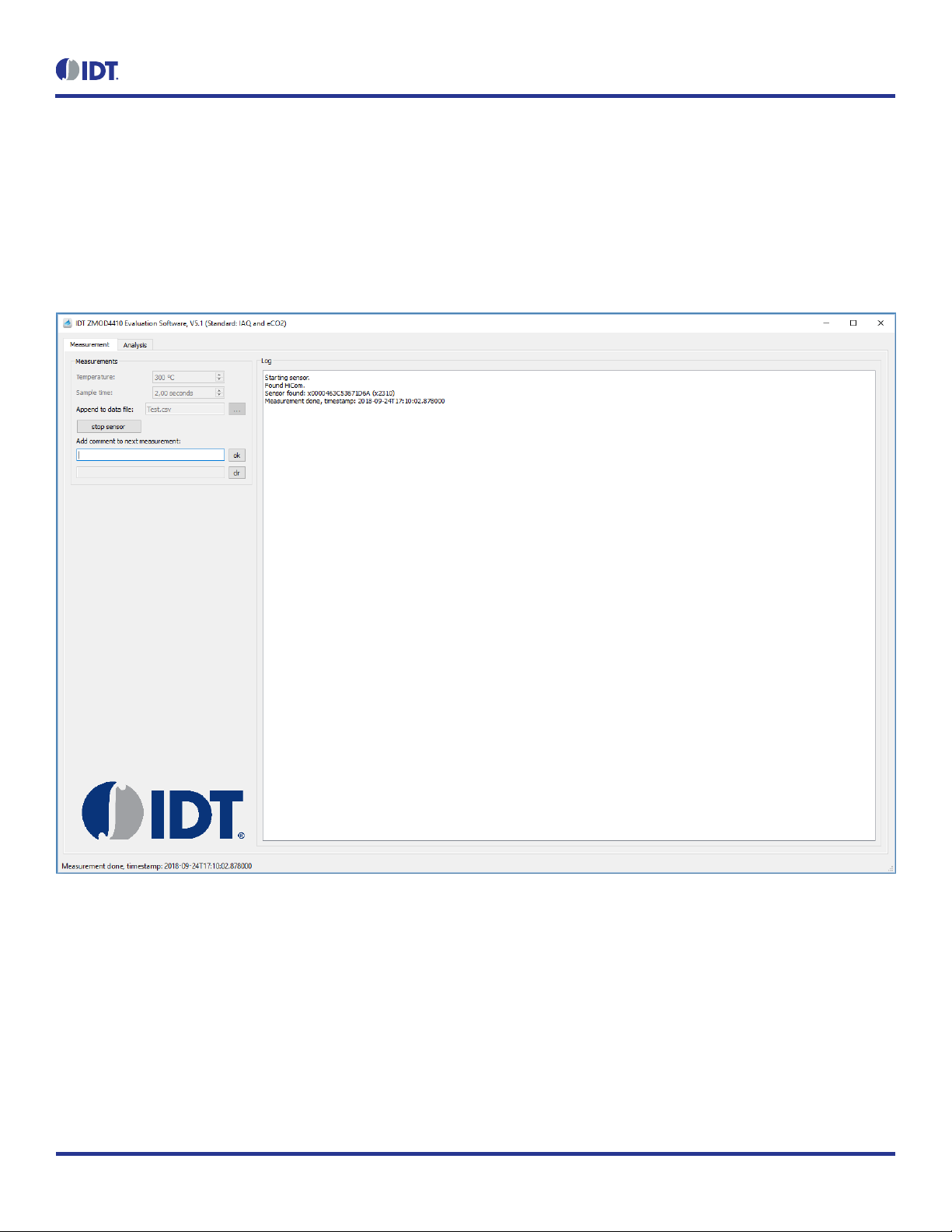
The ZMOD4410 Evaluation Software allows Windows®-based
operating systems to communicate with the ZMOD4410 EVK via a
USB connection on the user’s computer, which functions as a
master. The software and additional related documentation is
available on the IDT website.
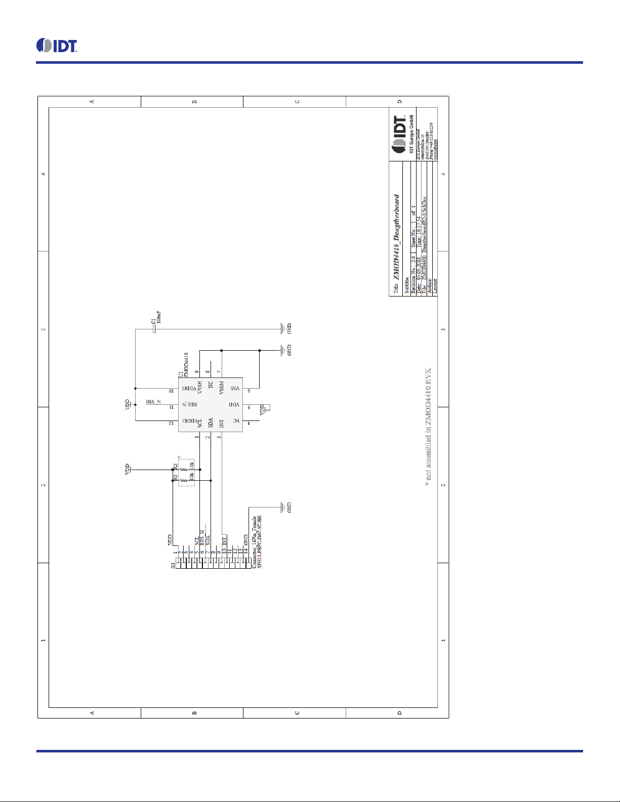
The EVK’s Communication Board (HiCom) handles the interface
between the user’s computer and the ZMOD4410 module mounted
on the ZMOD4410 Sensor Board (Daughter Board). Note: Only one
Communication Board with one Sensor Board can be connected to
the computer at a time.
The ZMOD4410 Evaluation Kit uses an FTDI controller on the
Communication Board to handle the USB protocol, translate
communications, and synchronize communications with the I2C
interface. The Sensor Board includes a decoupling capacitor.
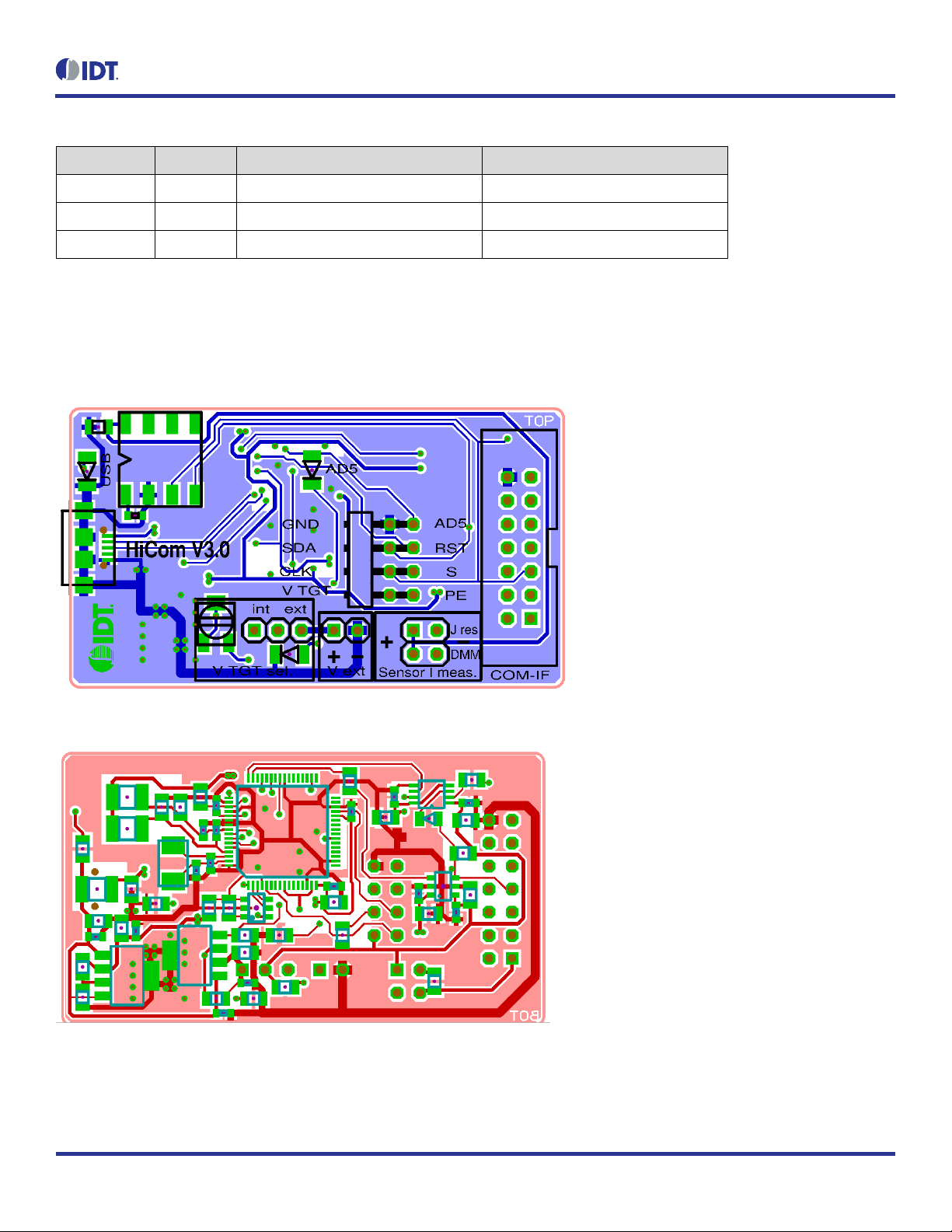
The Communication Board has devices mounted on both sides.
The components on the top side generate a stable supply voltage.
A potentiometer can be used to adjust the internal supply voltage
in the typical range from 1.7V to 3.6V. Alternatively, the user’s
external supply voltage can be used. The intensity of the adjacent
LED is proportional to the supply voltage.
Features
User-friendly EVK expedites configuration and evaluation of
the ZMOD4410 Gas Sensor
Operates with IDT provided software; either with executable
ZMOD4410 GUI or alternatively with firmware programming
examples for Windows and Linux
The modular design of the EVK allows simple connection of
Sensor Boards for different gas sensor derivatives and easy
integration with other sensor products via the I2C interface
The required ZMOD4410 Evaluation Software is available for
download on the IDT website, which also provides background
information on TVOC, gas sensing, and sensor programming.
Supports different methods of operation, including Low Power
Additional pins to measure power consumption, supply
voltage, and GPIO trigger for external device
The bill of materials (BOM) and schematics for the ZMOD4410
Communication Board and Sensor Board are provided at
www.IDT.com/ZMOD4410-EVK.
ZMOD4410-EVK Contents
ZMOD4410 HiCom Communication Board
ZMOD4410 Sensor Board with ZMOD4410 Gas Sensor
Module
0.5m Type-B USB to Micro-USB Cable
ZMOD4410 Evaluation Kit

ZMOD4410 Evaluation Kit User Manual
© 2019 Integrated Device Technology, Inc.
2
April 3, 2019
Important Notes
Disclaimer
Integrated Device Technology, Inc. and its affiliated companies (herein referred to as “IDT”) shall not be liable for any damages arising out of defects resulting from
(i) delivered hardware or software
(ii) non-observance of instructions contained in this manual and in any other documentation provided to user, or
(iii) misuse, abuse, use under abnormal conditions, or alteration by anyone other than IDT.
TO THE EXTENT PERMITTED BY LAW, IDT HEREBY EXPRESSLY DISCLAIMS AND USER EXPRESSLY WAIVES ANY AND ALL WARRANTIES, WHETHER
EXPRESS, IMPLIED, OR STATUTORY, INCLUDING, WITHOUT LIMITATION, IMPLIED WARRANTIES OF MERCHANTABILITY AND OF FITNESS FOR A
PARTICULAR PURPOSE, STATUTORY WARRANTY OF NON-INFRINGEMENT, AND ANY OTHER WARRANTY THAT MAY ARISE BY REASON OF USAGE
OF TRADE, CUSTOM, OR COURSE OF DEALING.
Restrictions in Use
IDT’s ZMOD4410 Evaluation Kit, consisting of the ZMOD4410 HiCom Communication Board, ZMOD4410 Sensor Board, and the ZMOD4410 Evaluation Software,
is designed for evaluation purpose only. IDT’s ZMOD4410 Evaluation Kit must not be used for calibration, test, qualification, or production.
Important Equipment Warning: Ensure the correct connection of all cables. Supplying the board using the wrong
polarity could result in damage to the board and/or the equipment. Check that all jumpers have been placed as
specified in this document.
Contents
1. Setup ............................................................................................................................................................................................................4
1.1 First Startup.........................................................................................................................................................................................4
1.2 Required or Recommended User Equipment......................................................................................................................................4
1.3 User Computer Requirements.............................................................................................................................................................4
1.3.1 Computer Requirements ......................................................................................................................................................4
1.4 Software Installation and Setup...........................................................................................................................................................4
1.5 EVK Hardware Connections and Initial Power-up ...............................................................................................................................5
2. Usage Guide.................................................................................................................................................................................................8
2.1 Software Modes...................................................................................................................................................................................9
2.1.1 “Measurement” Tab..............................................................................................................................................................9
2.1.2 “Analysis” Tab.......................................................................................................................................................................9
3. Schematics.................................................................................................................................................................................................13
4. Bill of Materials (BOM)................................................................................................................................................................................16
5. Board Layout ..............................................................................................................................................................................................18
6. Ordering Information...................................................................................................................................................................................20
7. Revision History..........................................................................................................................................................................................20
!

ZMOD4410 Evaluation Kit User Manual
© 2019 Integrated Device Technology, Inc.
3
April 3, 2019
List of Figures
Figure 1. Initial Display after Installation of the ZMOD4410 Evaluation Software...............................................................................................5
Figure 2. Jumper Settings and Connectors on the Top Side of the ZMOD4410 Communication Board............................................................6
Figure 3. Jumper Settings, Connections, and Test Points on the Communication Board for the Internal or External Supply Voltage...............7
Figure 4. Initial Display for ZMOD4410 Standard Operation Mode and Low Power Operation Mode................................................................8
Figure 5. “Analysis” Tab for Measurement Mode “Standard Operation” and “Low Power Operation”..............................................................10
Figure 6. “Analysis” Tab for Measurement Mode “Odor” ..................................................................................................................................11
Figure 7. Communication Board Schematic –Page 1......................................................................................................................................13
Figure 8. Communication Board Schematic –Page 2......................................................................................................................................14
Figure 9. Sensor Board Schematic...................................................................................................................................................................15
Figure 10. HiCom Communication Board Layout –Top Layer ...........................................................................................................................18
Figure 11. HiCom Communication Board Layout –Bottom Layer......................................................................................................................18
Figure 12. Sensor Board Layout –Top Layer.....................................................................................................................................................19
Figure 13. Sensor Board Layout –Bottom Layer ...............................................................................................................................................19
List of Tables
Table 1. Evaluation Kit Connection Descriptions...............................................................................................................................................6
Table 2. Analysis Tab User Options................................................................................................................................................................12
Table 3. Communication Board BOM..............................................................................................................................................................16
Table 4. Sensor Board BOM ...........................................................................................................................................................................18

ZMOD4410 Evaluation Kit User Manual
© 2019 Integrated Device Technology, Inc.
4
April 3, 2019
1. Setup
1.1 First Startup
To set-up and operate the ZMOD4410 Evaluation Kit (EVK) with the ZMOD4410, refer to the ZMOD4410 EVK Quick Start Guide document
included in the kit.
1.2 Required or Recommended User Equipment
By default, the internal supply voltage for powering the Sensor Board is generated from the USB voltage supplied by the user’s computer via
the USB cable. If there is a need for currents higher than the defined USB Standard (usually 500mA at 5V), an external voltage supply source
can be used instead of the internally generated voltage supply provided on the Communication Board. For details, see section 0.
The external supply powers only the sensor modules, and not the communication board itself. The supply must meet the following requirements:
Voltage. 1.7V to 3.6V
Current must meet the user’s specifications. The minimum is 30mA for electrics with additional need for each gas sensor module of
approximately 13mA (at 1.8V voltage supply).
1.3 User Computer Requirements
1.3.1 Computer Requirements
A Windows®-based computer is required for interfacing with the EVK and configuring the ZMOD4410. The user must have administrative rights
on the computer to download and install the ZMOD4410 Evaluation Software.
The computer must meet the following requirements:
1GB RAM
Hard drive with at least 500MB free space
1 USB port
Windows Vista/Windows 7/Windows 8/Windows 10
Internet access for initial download of the drivers and software
Important: Before installing and activating the software, assemble and connect the hardware for the kit to the user’s computer according to
steps 1 through 3 in section 0.
1.4 Software Installation and Setup
Before using the ZMOD4410 Evaluation Software, the USB drivers for the FTDI device must be installed. Download the drivers and
corresponding installation guides from the FTDI website (www.ftdichip.com). The drivers will not affect the operation of any other USB
peripherals. The kit does not need to be connected during installation of the drivers.
Follow these procedures to download and install the ZMOD4410 Evaluation Software with the kit connected:
1. Download the ZMOD4410 Evaluation Software zip file at www.IDT.com/ZMOD4410-EVK.
2. Create a folder on the user’s computer for the software (e.g., C:\Program Files (x86)\IDT Software). Extract the contents of the
downloaded zip file into this folder.
3. Double-click on the extracted batch file ZMOD4410_Evaluation_Software.bat to start the software. There is no need for an installation of
this software for user convenience. Figure 1 shows an example of the initial display after execution.
4. Select the measurement mode to run the sensor in “Standard Operation” or “Low Power Operation”to either measure IAQ/TVOC/eCO2,
or alternatively choose the “Odor” option to trigger the activation of an external device by changes in the air quality.

ZMOD4410 Evaluation Kit User Manual
© 2019 Integrated Device Technology, Inc.
5
April 3, 2019
Figure 1. Initial Display after Installation of the
ZMOD4410 Evaluation Software
1.5 EVK Hardware Connections and Initial Power-up
To set up the EVK hardware before using the software, complete the following procedure:
1. Refer to Figure 2, Figure 3, and Table 1 to determine the correct jumper settings for the ZMOD4410 Communication Board depending on
whether an external supply or the internal voltage supply on the board is used.
If the internal voltage supply is used, ensure that the jumper is across the pins labeled “int” on the K2 connector.
If using an external supply, ensure that the jumper is across the pins labeled “ext” on the K2 connector. In this case, without
connecting the external supply to the Communication Board, verify that the external voltage supply setting does not exceed the
voltage supply specifications -- a minimum of 1.7V or a maximum of 3.6V -- as per the ZMOD4410 Datasheet. With the external
supply off, connect the external voltage to the 2-pin “+ - V ext” header adjacent to the K2 jumper with the orientation indicated in
Figure 3. Note: If this option is used adjustments of the external voltage are not possible on either the Communication Board, or the
Sensor Board for adjusting an external voltage supply.
2. Install the ZMOD4410 Sensor Board on the 14-pin connector on the ZMOD4410 Communication Board taking care to ensure the proper
orientation of the Sensor Board as shown on page 1.
3. Insert the micro-USB cable into the X1 connector on the Communication Board and connect it to a free USB port on the user’s computer.
If the external voltage supply has been selected, turn on the external supply and verify that the D3 LED adjacent to the potentiometer
is on. See Figure 2. Note: The intensity of the green D3 LED is proportional to the supply voltage.
4. Activate the software as described in section 1.4.
5. If the internal voltage is used, the ZMOD4410 Evaluation Software activates the internal voltage after the sensor has been started. Use
the metal potentiometer to the left of the K2 connector to adjust the VDD supply voltage in the typical range from 1.7V to 3.6V as
measured across the V_TGT and GND pins available on the K3 connector as shown in Figure 3. Its initial adjustment on delivery
provides a voltage of VDD ≈2.0V. Once a measurement has been started by the software, the green D3 LED adjacent to K2 will light
with an intensity proportional to the voltage supply that was set using the potentiometer.
6. Verify that the red D1 LED is on, which indicates that the kit is properly connected and powered.
The Communication Board provides the additional K3 and Modul1 connectors for the following optional uses as described in Table 1. To
make use of any of these options, contact IDT for further instructions (see contact information on last page).
Extra measurement options (e.g., current consumption to determine the power requirements of the ZMOD4410)
Connections for additional sensors (e.g., IDT humidity sensor HS3001)

ZMOD4410 Evaluation Kit User Manual
© 2019 Integrated Device Technology, Inc.
6
April 3, 2019
Figure 2. Jumper Settings and Connectors on the Top Side of the ZMOD4410 Communication Board
Table 1. Evaluation Kit Connection Descriptions
Connector
Type
Description
K1
4-pin, 2-row header
This jumper can be used to break the supply voltage line to measure the current consumption of
a connected Sensor Board. Important: During normal operation, ensure that a jumper is on the
“DMM” position as shown in Figure 2.
K2
3-pin header
This jumper selects either the internal or external voltage supply. See Figure 3 for the proper
position for the jumper.
K3
8-pin, 2-row right-angle
header
This connector can be used to connect the ZMOD4410 in different configurations or to measure
the communication lines and voltages on the ZMOD4410 Sensor Board. AD5 is a GPIO pin that
can be controlled via the software in the “Odor”measurement mode.
K4
14-pin connector
This is the connector for installing the ZMOD4410 Sensor Board on the Communication Board.
K5
2-pin header
This is the connector for an optional external voltage supply (see Figure 3).
D1
Status LED
This LED lights if the Communication Board is powered correctly.
D2
Status LED
This LED lights if the trigger pin is set by the software.
D3
Status LED
This LED will light with an intensity proportional to the internal voltage supply that was set using
the potentiometer.
X1
Micro USB B-type
This is the micro-USB cable connector for connecting the Communication Board to the user’s
computer.
R19
Potentiometer
This resistor adjusts the internal supply voltage. It can be adjusted by rotating the resistor with a
small screwdriver.
Modul1
DIL socket
This socket can be used to add external components (e.g., a humidity sensor) to the
Communication Board. Contact IDT for further instructions.

ZMOD4410 Evaluation Kit User Manual
© 2019 Integrated Device Technology, Inc.
7
April 3, 2019
Figure 3. Jumper Settings, Connections, and Test Points on the Communication Board for the
Internal or External Supply Voltage

ZMOD4410 Evaluation Kit User Manual
© 2019 Integrated Device Technology, Inc.
8
April 3, 2019
2. Usage Guide
For all Measurement options, the ZMOD4410 Evaluation Software has two different tabs:
“Measurement”(section 2.1.1)
“Analysis”(section 2.1.2)
To select a tab, clicking on the name in the main screen. When the ZMOD4410 Evaluation Software is executed and the operation mode has
been selected, it shows the “Measurement”tab by default (see Figure 4).
Figure 4. Initial Display for ZMOD4410 Standard Operation Mode and Low Power Operation Mode
On the “Measurement” tab, the user can control the properties of the ZMOD4410’s gas measurements. When the “start sensor” button is clicked,
the measurement starts running continuously with the given sample time (2 seconds fixed for Standard Operation, 5 seconds (default) for Odor
Operation, and 6 seconds fixed for Low Power Operation). IDT sets 300°C as the default temperature.
On the “Analysis” tab, the measurements will be displayed and are processed by different algorithms to calculate the indoor air quality (IAQ)
and equivalent carbon dioxide (eCO2), or the algorithm output to control an external device. The algorithm takes the first 15 measurements for
stabilization. Other features such as TVOC concentration measurement, temperature measurement, and others are also possible. For further
instructions, contact IDT.
The different software tabs, buttons, and entry fields are described in the following sections.

ZMOD4410 Evaluation Kit User Manual
© 2019 Integrated Device Technology, Inc.
9
April 3, 2019
2.1 Software Modes
2.1.1 “Measurement”Tab
Click on the “Measurement” tab to display the measurement options. On this tab, the user can see the properties of the ZMOD4410’s gas
measurements, which includes setting the temperature in °C and changing the sample time in seconds used during the gas measurements.
The sampling rate in Standard Operation is fixed at 2 seconds, while in Low Power Operation it is fixed to 6 seconds. In Odor Operation, the
sample rate can be changed between 1 and 15 seconds.
When the “start sensor” button is clicked, the measurement starts running continuously with the interval selected under “Sample time” via the
up/down arrows. The results will be automatically added to the plots in the “Analysis” tab and continuously saved in a comma separated file
(CSV), which is user-selected via the file selection dialog accessed by clicking the “…” button adjacent to the “Append to data file” field, which
displays the selected path and file name.
A comment (for example, “Apply test gas”) can be added to the data entry by adding a string to the “Add comment to next measurement” field
and then clicking the “ok”button. If a measurement is already in progress, the comment will be added to the next measurement. If a comment
is on hold waiting for the next measurement, it can be deleted by clicking the “clr” button. The comments will be displayed in the plot shown on
the “Analysis” tab and will be saved in the CSV result file. This facilitates tracking the user’s experimental investigations.
2.1.2 “Analysis” Tab
Depending in the operation mode (“Standard”, “Low Power”, or “Odor”) the user will see slightly different screen.
For Standard Operation and Low Power Operation
Click on the tab to display the “Analysis”tab (see Figure 5). The “Analysis” tab shows three plots:
IAQ rating according to the standards of the German Federal Environmental Agency (UBA).
eCO2concentration (in ppm)
Raw sensor signal (in Ω)
For more information on IAQ and eCO2, refer to the ZMOD4410 White Paper –Overview of TVOC and Indoor Air Quality and the ZMOD4410
Application Note –Estimating Carbon Dioxide.
There are four sections for user interaction located above the graphs:
Data source
Misc
IAQ
eCO2

ZMOD4410 Evaluation Kit User Manual
© 2019 Integrated Device Technology, Inc.
10
April 3, 2019
Figure 5. “Analysis” Tab for Measurement Mode “Standard Operation” and “Low Power Operation”
For Odor Operation
Click on the tab to display the “Analysis” tab (see Figure 6). The “Analysis” tab shows two plots:
Algorithmic output signal with indication on trigger activation times (AD5 of connector K3)
Raw sensor signal (in Ω)
There are four sections for user interaction above the graphs:
Data source
Misc
Air Quality Change
Control Signal Generation

ZMOD4410 Evaluation Kit User Manual
© 2019 Integrated Device Technology, Inc.
11
April 3, 2019
Figure 6. “Analysis” Tab for Measurement Mode “Odor”
The available user options are described in Table 2 for all measurement modes.
The “Analysis” tab can be used to see the active measurement data and to load previously acquired measurement result files by using the “load
data file” button. For this usage, it is not necessary to connect the ZMOD4410 Evaluation Kit hardware. The “Analysis” tab supports data files
with data from multiple sensors if the loaded CSV file has the required format. One sensor will be processed and displayed at a time.
For Standard Operation and Low Power Operation, the default algorithms applied in the “Analysis” tab calculate gas concentrations for eCO2
and IAQ. Other algorithm results –e.g., calculations of concentrations of ethanol and total volatile organic compounds (TVOC) –are available
upon request.
The algorithm results will be displayed as a colored bar in the “Algorithm Result” section above the graphs (see Table 2) and in the “Algorithm
Result” plots. The first 15 measurements after the start of a measurement are taken for initialization process. To export the data from the
“Analysis” tab into a separate measurement file (CSV), click the “export data” button. Note that only the data shown in the recent plots will be
exported.

ZMOD4410 Evaluation Kit User Manual
© 2019 Integrated Device Technology, Inc.
12
April 3, 2019
Table 2. Analysis Tab User Options
Display Section
Button/Action
Description
“Data source”
The “clear memory” button will delete all current data from the plots (memory). The data in
the measurement file will remain.
The “load data file” button will open a file selection dialog. This function can be used to
display and analyze data from a measurement file acquired earlier. The data file must have
the same structure as the measurement file created by the ZMOD4410 Evaluation Software.
The “append incoming sensor data” checkbox activates the functionality to append the
current measurement data to the plots in the “Analysis” tab.
If measurements are acquired simultaneously for multiple ZMOD4410 gas sensors, the
measurement results file can contain data from different sensors. In the “Sensor” drop-down
menu, the user can choose a sensor to display by selecting the unique sensor identification
number.
Initial Stabilization
The first measurements of the algorithm will be taken for sensor stabilization. The “Algorithm
Result” field will indicate how many measurements have been completed during this period.
Raw sensor signals are shown on the “Sensor Signal (Ohms)” plot during this time, but the
algorithm results are only calculated after stabilization. Note that this does not cover the full
stabilization of the sensor module but rather covers only the first minutes during startup.
Recommendation: IDT recommends a sample time of 2 seconds for these 15 measurements
resulting in 30 seconds for the initialization measurements.
Algorithm Result for
“Standard Operation”
and
“Low Power Operation”
After the stabilization measurements, the “Algorithm Result” field shows a colored bar
representing the results from the algorithm. The IAQ rating from the Federal German
Environmental Agency (UBA) and the corresponding IDT IAQ rating are shown.
IDT’s patented smart algorithm will provide eCO2 readings with high accuracy when
activated (default). However, for demonstration reasons it might be useful to disable the
eCO2 algorithm to see very fast CO2 changes directly related to the VOC level.
Algorithm Result
“Odor Operation”
After the stabilization measurements, the “Algorithm Result” field shows a colored bar
representing the results from the algorithm. The Air Quality Change is shown in three
categories:
< 10% Minor changes or improvement in Air Quality: Control Signal Off
10% to 30% Slight change in Air Quality: Control Signal Off
> 30% Major change in Air Quality: Control Signal On
The threshold is set to 1.3 (default value). This means only a 30% Signal Change will lead to
set the Control Signal to On status.
After the Air Quality has improved the control signal will remain On for 24 samples (2
minutes for default operation) to avoid a hysteresis. This Control Signal triggers the AD5
GPIO pin on the HiCom board and its status is shown in the on/off field.
“Misc”
The drop-down menu adjacent to the “show” button provides options for selecting the time
period for showing the recent history or the complete data. Click the “show” button to apply
new settings to the plots.
The “export data” button will open a file selection dialog for selecting a path to immediately
save the measurement results and the processed algorithm results of the “Analysis” tab. The
file will be saved in comma-separated format (CSV).

ZMOD4410 Evaluation Kit User Manual
© 2019 Integrated Device Technology, Inc.
13
April 3, 2019
3. Schematics
Figure 7. Communication Board Schematic –Page 1

ZMOD4410 Evaluation Kit User Manual
© 2019 Integrated Device Technology, Inc.
14
April 3, 2019
Figure 8. Communication Board Schematic –Page 2

ZMOD4410 Evaluation Kit User Manual
© 2019 Integrated Device Technology, Inc.
15
April 3, 2019
Figure 9. Sensor Board Schematic

ZMOD4410 Evaluation Kit User Manual
© 2019 Integrated Device Technology, Inc.
16
April 3, 2019
4. Bill of Materials (BOM)
Table 3. Communication Board BOM
Pos
Name
Value
Package
1
C3
10µF/16V
0805
2
C5
100nF
0603
3
C6
10nF
0805
4
C7
100nF
0603
5
C8
100nF
0603
6
C9
10µF/16V
0805
7
C10
10µF/16V
0805
8
C11
10µF/16V
0805
9
C12
100nF
0603
10
C13
100nF
0603
11
C14
100nF
0603
12
C15
100nF
0603
13
C16
100nF
0603
14
C17
10µF/16V
0805
15
C18
27pF
0603
16
C19
27pF
0603
17
C20
10µF/16V
0805
18
C21
10µF/16V
0805
19
C22
100nF
0603
20
C23
100nF
0603
21
C24
10µF/16V
0805
22
C25
100nF
0603
23
C26
100nF
0603
24
C27
10µF/16V
0805
25
C28
100nF
0603
26
C29
10µF/16V
0805
27
C30
100nF
0603
28
C31
220nF
0805
29
D1
LED 1206RT
1206-DIODE
30
D2
LED 1206GN
1206-DIODE
31
D3
LED 1206GN
1206-DIODE
32
D4
SD0805S040S0R1-SCHOTTKY
0805-DIODE
33
IC1
LP38692-adj
SOT-223-5

ZMOD4410 Evaluation Kit User Manual
© 2019 Integrated Device Technology, Inc.
17
April 3, 2019
Pos
Name
Value
Package
34
IC2
LP38692-adj
SOT-223-5
35
IC3
93LC46B
SOT23-6
36
IC4
FT2232HL
LQFP64
37
IC6
SN74LVC1T45
SOT23-6
38
IC8
SN74LVC2T45DCT
SSOP8_0,65
39
K1
I_meas
2X02
40
K2
Select
1X03
41
K3
K2X4
2X04-90
42
K4
K2X7
LH-14
43
K5
V_EXT
1X02
44
L1
10µH
1210
45
L2
10µH
1210
46
L3
10µH
1210
47
Modul1
Honeywell480-3652-1-ND
DIL8 SMD SOCKEL
48
Q1
12.00MHz
QUARZ-ABM3
49
R1
1kΩ
0805
50
R2
1kΩ
0805
51
R3
1.6kΩ
0805
52
R4
12kΩ
0805
53
R5
47kΩ
0805
54
R6
2.2kΩ
0805
55
R7
10kΩ
0805
56
R8
1kΩ
0805
57
R13
51Ω
0805
58
R15
51Ω
0805
59
R16
10Ω
0805
60
R17
1kΩ
0805
61
R18
470Ω
0805
62
R19
2.0kΩ
TRIMMER-3142SERIES
63
R20
1kΩ
0805
64
R21
10kΩ
0805
65
R22
2.0kΩ
0805
66
R23
2.0kΩ
0805
67
X1
USB-micro-B-5pol-SMD-Bu
USB-MICRO_TYPB_AMTEK

ZMOD4410 Evaluation Kit User Manual
© 2019 Integrated Device Technology, Inc.
18
April 3, 2019
Table 4. Sensor Board BOM
Designator
Quantity
Manufacturer
Manufacturer Part Number
C1
1
Taiyo Yuden
LMK105BJ104KV-F
U1
1
IDT
ZMOD4410
X1
1
Sullins
SFH11-PBPC-D07-ST-BK
5. Board Layout
Figure 10. HiCom Communication Board Layout –Top Layer
Figure 11. HiCom Communication Board Layout –Bottom Layer

ZMOD4410 Evaluation Kit User Manual
© 2019 Integrated Device Technology, Inc.
19
April 3, 2019
Figure 12. Sensor Board Layout –Top Layer
Figure 13. Sensor Board Layout –Bottom Layer

ZMOD4410 Evaluation Kit User Manual
© 2019 Integrated Device Technology, Inc.
20
April 3, 2019
6. Ordering Information
Orderable Part Number
Description
ZMOD4410-EVK-HC
ZMOD4410 Evaluation Kit including the ZMOD4410 Sensor Board, ZMOD4410 HiCom Communication Board
(USB Interface), and Micro-USB Cable. (The ZMOD4410 Evaluation Software is available for download free of
charge on www.IDT.com/ZMOD4410-EVK.)
7. Revision History
Revision Date
Description of Change
April 3, 2019
Updateson Odor operation mode.
November 1, 2018
Updated with Low Power operation mode.
September 25, 2018
Updated with Odor operation mode.
May 19, 2018
Initial release.
Corporate Headquarters
6024 Silver Creek Valley Road
San Jose, CA 95138
www.IDT.com
Sales
1-800-345-7015 or 408-284-8200
Fax: 408-284-2775
www.IDT.com/go/sales
Tech Support
www.IDT.com/go/support
DISCLAIMER Integrated Device Technology, Inc. (IDT) and its affiliated companies (herein referred to as “IDT”) reserve the right to modify the products and/or specifications described herein at an y time,
without notice, at IDT's sole discretion. Performance specifications and operating parameters of the described products are determined in an independent state and are not guaranteed to perform the same
way when installed in customer products. The information contained herein is provided without representation or warranty of a ny kind, whether express or implied, including, but not limited to, the suitability
of IDT's products for any particular purpose, an implied warranty of merchantability, or non -infringement of the intellectual property rights of others. This document is presented only as a guide and does not
convey any license under intellectual property rights of IDT or any third parties.
IDT's products are not intended for use in applications involving extreme environmental conditions or in life support systems or similar devices where the failure or malfunction of an IDT product can be
reasonably expected to significantly affect the health or safety of users. Anyone using an IDT product in such a manner does so at their own risk, absent an express, written agreement by IDT.
Integrated Device Technology, IDT and the IDT logo are trademarks or registered trademarks of IDT and its subsidiaries in the United States and other countries. Other trade marks used herein are the
property of IDT or their respective third party owners. For datasheet type definitions and a glossary of common terms, visit www.idt.com/go/glossary. All contents of this document are copyright of Integrated
Device Technology, Inc. All rights reserved.
Table of contents
Other IDT Motherboard manuals

IDT
IDT 9ZXL1951D User manual

IDT
IDT 82V3911 User manual

IDT
IDT 89EBPES48H12 User manual

IDT
IDT 8T49N240 User manual

IDT
IDT 8T49N24 Series Installation and operating instructions

IDT
IDT 89EBPES24T3G2 User manual

IDT
IDT P9242-R-EVK User manual

IDT
IDT 89EBPES16NT2 User manual

IDT
IDT PhiClock 9FGV1001 User manual

IDT
IDT 89EBPES12N3 User manual

IDT
IDT Tsi620 User manual

IDT
IDT ZSSC4151 User guide

IDT
IDT 8A34 Series User manual

IDT
IDT EB-LOGAN-23 User manual

IDT
IDT VersaClock 6E 5P49V6965 User manual

IDT
IDT ZMOD4510-EVK User manual

IDT
IDT 9FGV1005 Operating instructions

IDT
IDT Tsi381 User manual

IDT
IDT Tsi382 LQFP User manual

IDT
IDT VersaClock 3S User manual