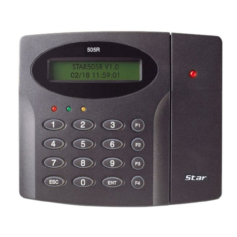
The most important point for grounding system is not to connect both ends of shield wires to the grounding system; in
this case there will be a current flow through the shield wire when the voltage level of both ends of shield wire is not
equal and this current flow will create noise and interfere to communications.
For the good grounding, we recommend connecting ONLY one end of shield wire of communication cable to the
grounding system; If you find earth ground nearby, then connect one end of shield wire to earth ground; If you do not
have earth ground nearby, then find chassis ground and connect one end of shield wire to chassis ground; If you do
not find both earth ground and chassis ground, then connect one end of shield wire to power ground. (GND of Star
505R)
Note that if the chassis ground is not properly connected to the earth and floated from the ground level, then grounding
to the chassis ground will give the worst communication; in this case we recommend to using power ground instead of
chassis ground.
Figure: Grounding System
4.2.4 Reverse Diode Connection
If you connect an inductor (Door Locks or Alarm device) to the output relays, there will be a high surge voltage created
while the inductor is turning on and off. If you do not connect reverse diode, the surge voltage will transfer and damage
to the electronic circuit of the controller. It is strongly recommended to add a reverse diode between the inductor coils
to absorb this surge voltage.
Figure: Reverse Diode Connection
5. INSTALLATION
5.1 Wall Mount Installation
Real size template is on back of this manual. Tear off the template page and attach it to the wall. And then follow steps
below to install the Star 505R. (You can install the Star 505R directly, if the gang box is installed on the wall.)
1. Position the Wall Mount template to the location at which you want to install the unit and mark 2 drilling (two Tap #6-
32 holes) positions and then drill it
