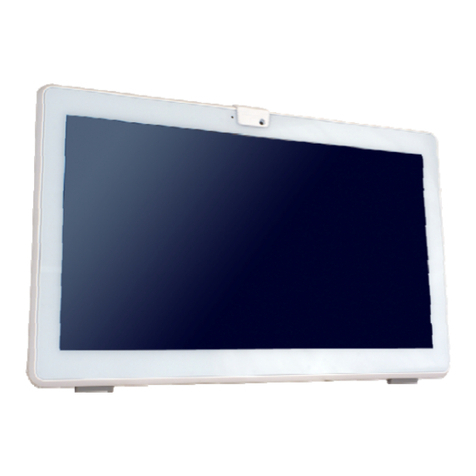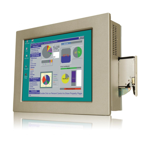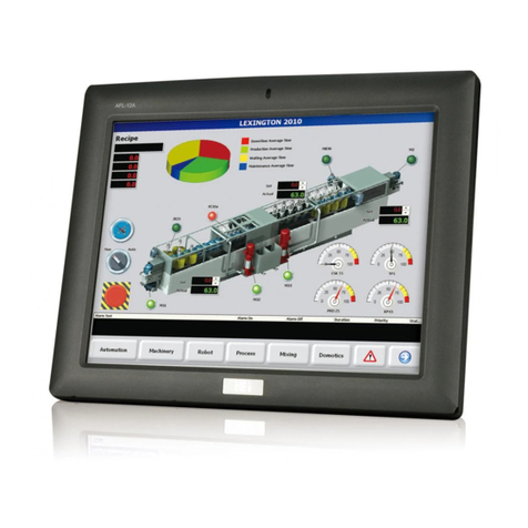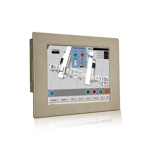
PPC-5152-D525 Flat-bezel Panel PC
Page vi
3.10.1 Arm Mounting................................................................................................ 32
3.10.2 Panel Mounting.............................................................................................. 34
3.10.3 Rack/Cabinet Mounting................................................................................. 36
3.10.4 Stand Mounting.............................................................................................. 38
3.10.5 Wall Mounting................................................................................................ 39
3.11 BOTTOM PANEL CONNECTORS................................................................................ 42
3.11.1 Audio Connectors........................................................................................... 42
3.11.2 LAN Connector............................................................................................... 43
3.11.3 Power Input, 2-pin Terminal Block................................................................ 44
3.11.4 Power Input, DIN Connector ......................................................................... 45
3.11.5 RS-232 Serial Port (COM1, COM2).............................................................. 46
3.11.6 RS-232/422/485 Serial Port (COM3)............................................................. 47
3.11.6.1 COM3 Mode Select Switch .................................................................... 48
3.11.7 RJ-45 RS-422/485 Serial Port (COM4, COM5) ............................................ 49
3.11.8 SFP Fiber Connectors.................................................................................... 51
3.11.9 USB 2.0 Connectors....................................................................................... 51
3.11.10 USB 3.0 Connectors..................................................................................... 52
3.11.11 VGA Connector............................................................................................. 53
3.12 POWER-UP THE SYSTEM......................................................................................... 55
3.12.1 AT/ATX Power Mode Selection...................................................................... 55
3.12.2 Powering On/Off in ATX Power Mode.......................................................... 56
3.13 REMOTE CONTROL................................................................................................. 56
4 SYSTEM MAINTENANCE ....................................................................................... 57
4.1 SYSTEM MAINTENANCE INTRODUCTION.................................................................. 58
4.2ANTI-STATIC PRECAUTIONS...................................................................................... 58
4.3 TURN OFF THE POWER.............................................................................................. 59
4.4 OPENING THE SYSTEM.............................................................................................. 59
4.5 REPLACING COMPONENTS........................................................................................ 60
4.5.1 Memory Module Replacement ......................................................................... 60
4.5.2 WLAN Card Replacement ................................................................................ 61
5 AMI BIOS SETUP....................................................................................................... 65
5.1 INTRODUCTION......................................................................................................... 66
5.1.1 Starting Setup................................................................................................... 66
