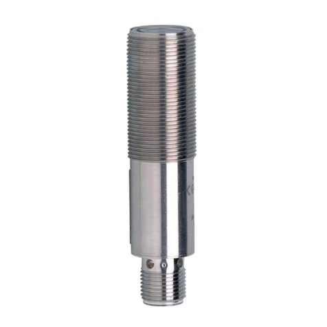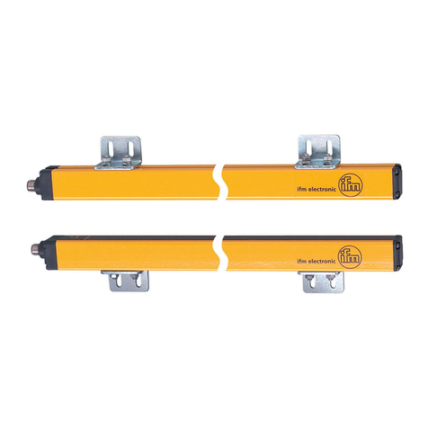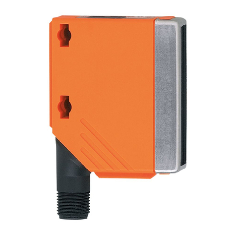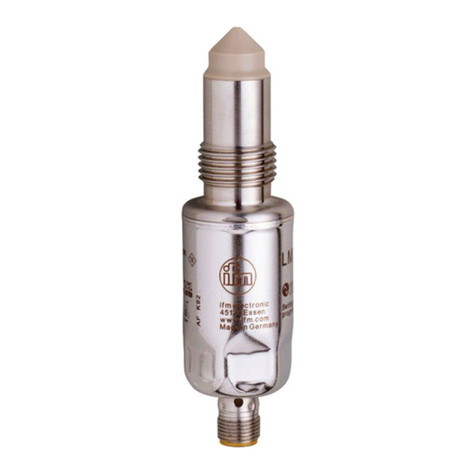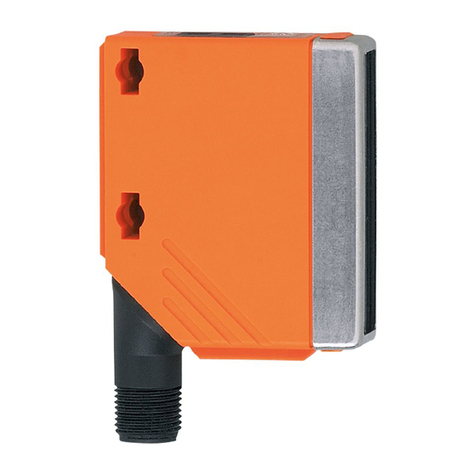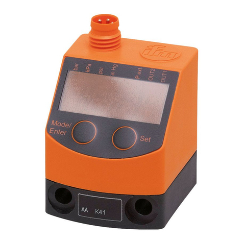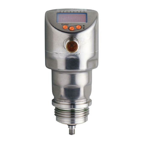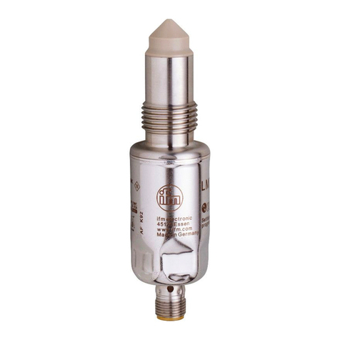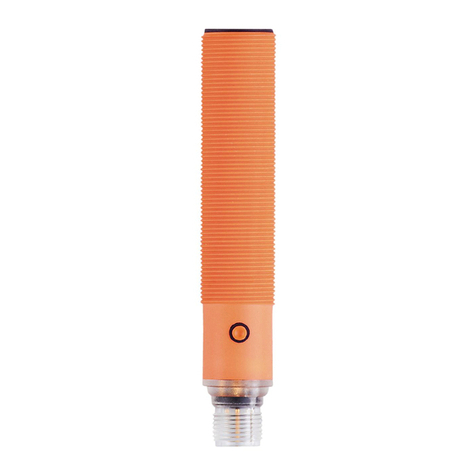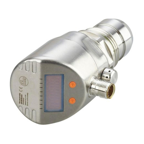
SBY2xx SBG2xx SBN2xx Mechatronic flow sensor
2
Contents
1 Preliminary note ............................................................. 4
1.1 Symbols used.......................................................... 4
1.2 Warnings used ......................................................... 4
2 Safety instructions............................................................ 5
3 Intended use................................................................ 6
4 Function ................................................................... 7
4.1 Output OUT1 selection options............................................. 7
4.2 Output OUT2 selection options............................................. 7
4.3 Switching output........................................................ 7
4.4 Analogue output........................................................ 8
4.4.1 Volumetric flow monitoring ............................................ 8
4.4.2 Temperature monitoring .............................................. 9
4.5 Frequency output ....................................................... 9
4.5.1 Volumetric flow monitoring ............................................ 10
4.5.2 Temperature monitoring .............................................. 10
4.6 Display colour setting .................................................... 10
4.7 IO-Link ............................................................... 11
5 Mounting................................................................... 12
5.1 Process connection...................................................... 12
5.2 Interference............................................................ 12
5.3 Mounting accessories.................................................... 13
5.4 Installation in case of medium containing dirt . . . . . . . . . . . . . . . . . . . . . . . . . . . . . . . . . . 13
6 Electrical connection.......................................................... 14
7 Operating and display elements................................................. 15
8 Menu...................................................................... 16
8.1 Menu overview......................................................... 16
8.2 Main menu and submenus ................................................ 16
9 Set-up..................................................................... 19
10 Parameter setting............................................................ 20
10.1 Parameter setting via IO-Link.............................................. 20
10.1.1 Identification....................................................... 20
10.1.1.1 Application Specific Tag......................................... 20
10.1.2 Parameters........................................................ 20
10.1.2.1 Access locks to the units: Local parameter setting . . . . . . . . . . . . . . . . . . . . . 20
10.2 Parameter setting via the unit keys . . . . . . . . . . . . . . . . . . . . . . . . . . . . . . . . . . . . . . . . . . 21
10.2.1 Parameter setting in general........................................... 21
10.2.2 Presets........................................................... 21
10.2.2.1 Process value for OUTx ......................................... 21
10.2.2.2 Standard unit of measurement . . . . . . . . . . . . . . . . . . . . . . . . . . . . . . . . . . . . 21
10.2.3 Setting the output functions............................................ 22
10.2.3.1 Limit monitoring OUTx/ hysteresis function . . . . . . . . . . . . . . . . . . . . . . . . . . 22
10.2.3.2 Limit monitoring OUTx/ window function . . . . . . . . . . . . . . . . . . . . . . . . . . . . 22
10.2.3.3 Frequency signal OUT1 ......................................... 22
10.2.3.4 Analogue signal OUT2 .......................................... 22
10.2.4 User settings (optional)............................................... 22
10.2.4.1 Standard display............................................... 22
10.2.4.2 Display colour setting ........................................... 23
10.2.4.3 Medium...................................................... 23
10.2.4.4 Output logic................................................... 23
10.2.4.5 Measured value damping for switching output. . . . . . . . . . . . . . . . . . . . . . . . . 23
10.2.4.6 Measured value damping for analogue output. . . . . . . . . . . . . . . . . . . . . . . . . 23
10.2.4.7 Error behaviour of the outputs. . . . . . . . . . . . . . . . . . . . . . . . . . . . . . . . . . . . . 23
10.2.4.8 Lock / unlock.................................................. 24
10.2.4.9 Factory reset.................................................. 24
10.2.5 Diagnostic functions ................................................. 24
