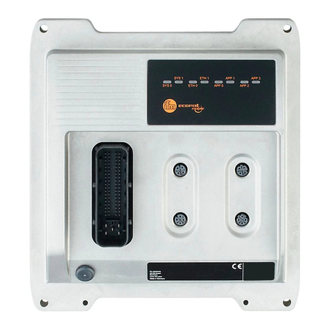
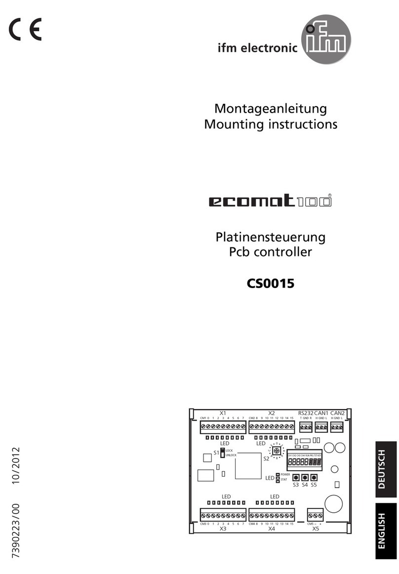
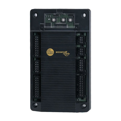
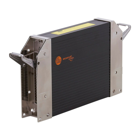
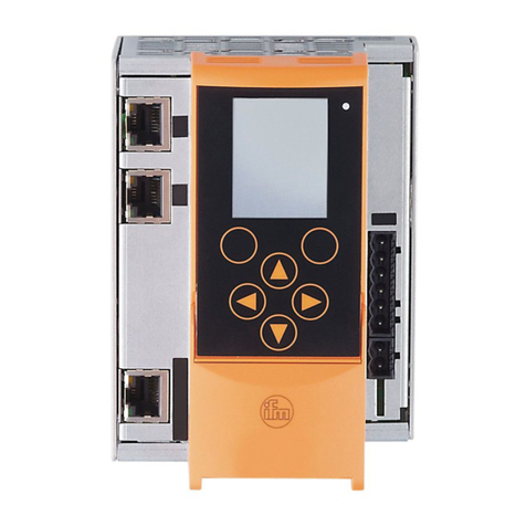
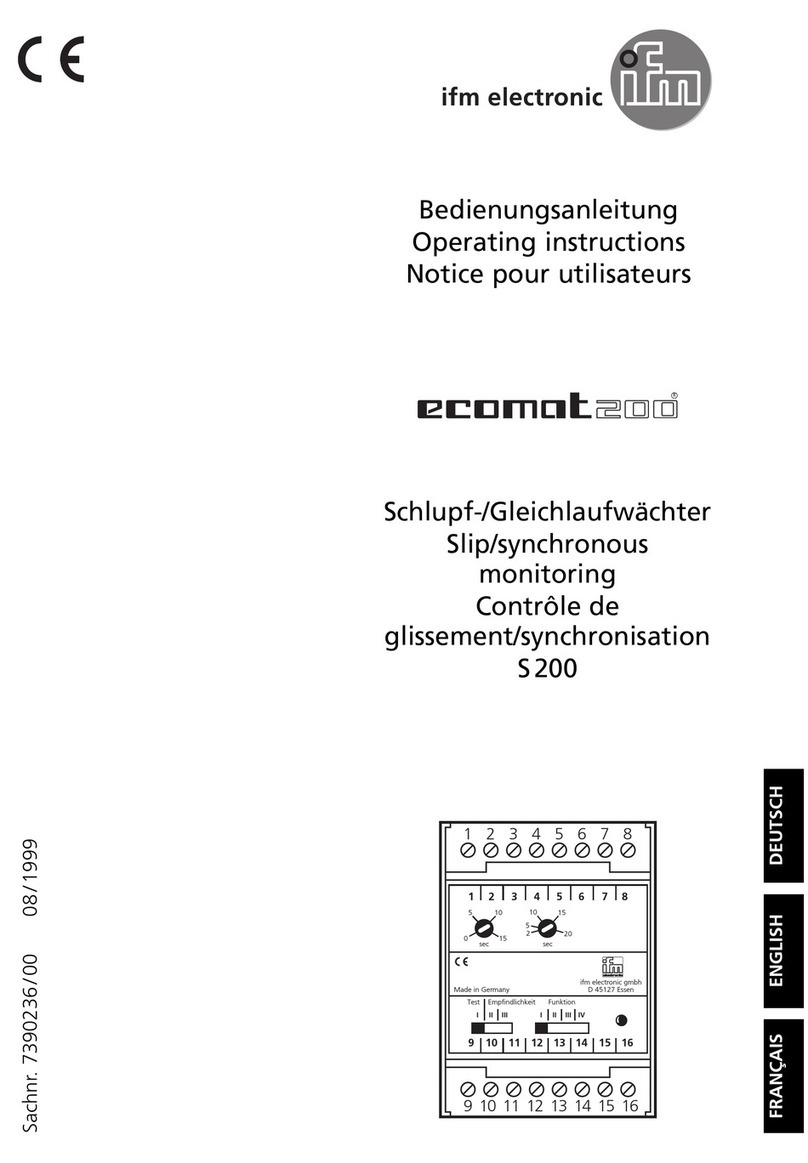
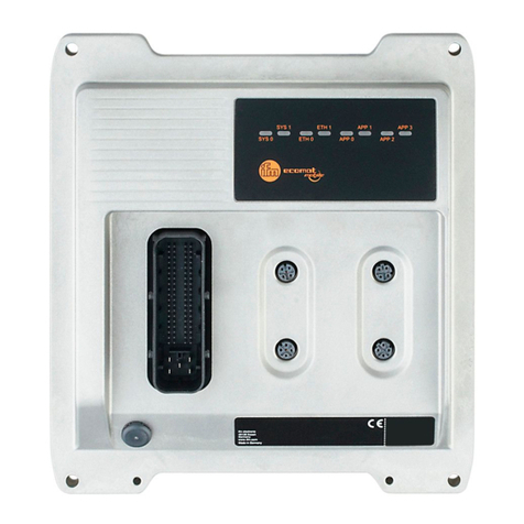
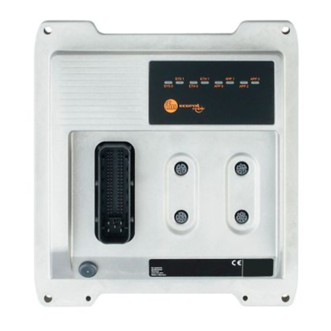
IFM Ecomat 100 Mobile CR0301 Owner's manual

1
Original Programming Manual
CabinetController
CR0301
Runtime system V05
CODESYS
®
> V2.3.9.33 (< V 3.0)
English
7391083_01_UK 2016-04-21

2
ifm Programming Manualecomatmobile CabinetController (CR0301) Runtime System V05 2016-04-21
Contents
Contents
1About this manual 4
1.1 Copyright..............................................................................................................................4
1.2 Overview: documentation modules for ecomatmobile devices............................................5
1.3 CODESYS programming manual ........................................................................................5
1.4 What do the symbols and formats mean?...........................................................................6
1.5 How is this documentation structured?................................................................................7
1.6 History of the instructions (CR030n)..................................................................................8
2Safety instructions 9
2.1 Please note!.........................................................................................................................9
2.2 What previous knowledge is required?..............................................................................10
2.3 Start-up behaviour of the controller....................................................................................10
2.4 Notes: serial number..........................................................................................................11
2.5 Notes: TEST inputs............................................................................................................11
3System description 12
3.1 Information about the device..............................................................................................12
3.2 Hardware description.........................................................................................................12
3.2.1 Hardware structure.....................................................................................................................13
3.2.2 Monitoring concept.....................................................................................................................15
3.2.3 Inputs (technology).....................................................................................................................17
3.2.4 Outputs (technology)..................................................................................................................21
3.2.5 Note on wiring ............................................................................................................................24
3.2.6 Safety instructions about Reed relays........................................................................................24
3.2.7 Status LED.................................................................................................................................25
3.3 Interface description...........................................................................................................26
3.3.1 Serial interface ...........................................................................................................................26
3.3.2 CAN interfaces ...........................................................................................................................27
3.4 Software description ..........................................................................................................28
3.4.1 Software modules for the device................................................................................................28
3.4.2 Programming notes for CODESYS projects...............................................................................31
3.4.3 Operating states.........................................................................................................................35
3.4.4 Operating modes........................................................................................................................39
3.4.5 Performance limits of the device ................................................................................................41
4Configurations 42
4.1 Set up the runtime system.................................................................................................42
4.1.1 Reinstall the runtime system ......................................................................................................43
4.1.2 Update the runtime system.........................................................................................................44
4.1.3 Verify the installation..................................................................................................................44
4.2 Set up the programming system........................................................................................45
4.2.1 Set up the programming system manually.................................................................................45
4.2.2 Set up the programming system via templates...........................................................................47
4.3 Function configuration of the inputs and outputs...............................................................48
4.3.1 Configure inputs.........................................................................................................................49
4.3.2 Configure outputs.......................................................................................................................52
4.4 Note on wiring....................................................................................................................54
4.5 Safety instructions about Reed relays ...............................................................................54

3
ifm Programming Manualecomatmobile CabinetController (CR0301) Runtime System V05 2016-04-21
Contents
5ifm function elements 55
5.1 ifm libraries for the device CR0301....................................................................................55
5.1.1 Bibliothek ifm_CR0301_V05yyzz.LIB.........................................................................................56
5.1.2 Library ifm_CR0301_CANopenMaster_V04yynn.LIB.................................................................58
5.1.3 Library ifm_CR0301_CANopenSlave_V04yynn.LIB...................................................................58
5.1.4 Library ifm_CAN1_EXT_Vxxyyzz.LIB.........................................................................................59
5.1.5 Bibliothek ifm_J1939_1_Vxxyyzz.LIB.........................................................................................59
5.2 ifm function elements for the device CR0301....................................................................60
5.2.1 Function elements: CAN layer 2.................................................................................................60
5.2.2 Function elements: CANopen master.........................................................................................76
5.2.3 Function elements: CANopen slave...........................................................................................86
5.2.4 Function elements: CANopen SDOs..........................................................................................94
5.2.5 Function elements: SAE J1939..................................................................................................99
5.2.6 Function elements: serial interface...........................................................................................111
5.2.7 Function elements: Optimising the PLC cycle via processing interrupts ..................................116
5.2.8 Function elements: processing input values.............................................................................122
5.2.9 Function elements: adapting analogue values.........................................................................127
5.2.10 Function elements: counter functions for frequency and period measurement........................130
5.2.11 Function elements: PWM functions..........................................................................................140
5.2.12 Function elements: controllers..................................................................................................149
5.2.13 Function elements: software reset............................................................................................158
5.2.14 Function elements: measuring / setting of time........................................................................160
5.2.15 Function elements: saving, reading and converting data in the memory..................................163
5.2.16 Function elements: data access and data check......................................................................170
6Diagnosis and error handling 177
6.1 Diagnosis .........................................................................................................................177
6.2 Fault .................................................................................................................................177
6.3 Reaction in case of an error.............................................................................................178
6.4 Reaction in case of a system error ..................................................................................178
6.5 CAN / CANopen: errors and error handling.....................................................................178
7Appendix 179
7.1 System flags.....................................................................................................................179
7.1.1 System flags: CAN...................................................................................................................180
7.1.2 System flags: error flags...........................................................................................................180
7.1.3 System flags: status LED .........................................................................................................181
7.1.4 System flags: voltages..............................................................................................................181
7.1.5 System flags: inputs and outputs..............................................................................................182
7.1.6 System flags: system ...............................................................................................................182
7.2 Address assignment and I/O operating modes................................................................183
7.2.1 Addresses / variables of the I/Os..............................................................................................183
7.2.2 Possible operating modes inputs/outputs.................................................................................187
7.3 Error tables.......................................................................................................................190
7.3.1 Error flags.................................................................................................................................190
7.3.2 Errors: CAN / CANopen............................................................................................................190
8Glossary of Terms 191
9Index 204
10 Notizen • Notes • Notes 208
11 ifm weltweit • ifm worldwide • ifm à l’échelle internationale 213
4
ifm Programming Manualecomatmobile CabinetController (CR0301) Runtime System V05 2016-04-21
About this manual Copyright
1About this manual
Copyright............................................................................................................................................... 4
Overview: documentation modules for ecomatmobile devices............................................................. 5
CODESYS programming manual.......................................................................................................... 5
What do the symbols and formats mean?............................................................................................. 6
How is this documentation structured? ................................................................................................. 7
History of the instructions (CR030n) ................................................................................................... 8
202
>
1.1 Copyright 6088
© All rights reserved by ifm electronic gmbh. No part of this manual may be reproduced and used
without the consent of ifm electronic gmbh.
All product names, pictures, companies or other brands used on our pages are the property of the respective rights owners:
• AS-i is the property of the AS-International Association, (→www.as-interface.net)
• CAN is the property of the CiA (CAN in Automation e.V.), Germany (→www.can-cia.org)
• CODESYS™ is the property of the 3S – Smart Software Solutions GmbH, Germany (→www.codesys.com)
• DeviceNet™ is the property of the ODVA™ (Open DeviceNet Vendor Association), USA (→www.odva.org)
• EtherNet/IP® is the property of the →ODVA™
• IO-Link®(→www.io-link.com) is the property of the →PROFIBUS Nutzerorganisation e.V., Germany
• ISOBUS is the property of the AEF – Agricultural Industry Electronics Foundation e.V., Deutschland
(→www.aef-online.org)
• Microsoft®is the property of the Microsoft Corporation, USA (→www.microsoft.com)
• PROFIBUS®is the property of the PROFIBUS Nutzerorganisation e.V., Germany (→www.profibus.com)
• PROFINET®is the property of the →PROFIBUS Nutzerorganisation e.V., Germany
• Windows®is the property of the →Microsoft Corporation, USA

5
ifm Programming Manualecomatmobile CabinetController (CR0301) Runtime System V05 2016-04-21
About this manual Overview:documentation modulesfor ecomatmobile devices
>
1.2 Overview: documentation modules for ecomatmobile devices
17405
The documentation for ecomatmobile devices consists of the following modules:
1. Data sheet
Contents Technical data in a table
Source →www.ifm.com > select your country > [Data sheet search] > CR0301 > [Technical data in PDF format]
2. Installation instructions / operating instructions
Contents Instructions for installation, electrical installation, (commissioning*), technical data
Source The instructions are supplied with the device
They are also found on ifm's homepage:
→www.ifm.com > select your country > [Data sheet search] > CR0301 > [Operating instructions]
3. Programming manual + online help
Contents Description of the configuration and the functions of the device software
Source →www.ifm.com > select your country > [Data sheet search] > CR0301 > [Operating instructions]
4. System manual "Know-how ecomatmobile"
Contents Know-how about the following topics:
• Overview Templates and demo programs
• CAN, CANopen
• Control outputs
• User flash memory
• Visualisations
• Overview of the files and libraries used
Source →www.ifm.com > select your country > [Data sheet search] > CR0301 > [Operating instructions]
5. System manual "The ISOBUS in the ifm controller"
Contents Description of the configuration and the functions of the ISOBUS software in the device
Source →www.ifm.com > select your country > [Data sheet search] > CRnnnn > [Operating instructions]
thereby "CRnnnn" stands for the articel numbers of the deviceswhich are pre-installed with ISOBUS
*) The descriptions in brackets are only included in the instructions of certain devices.
>
1.3 CODESYS programming manual 17542
In the additional "Programming Manual for CODESYS V2.3" you obtain more details about the use of
the programming system.
This manual can be downloaded free of charge from ifm's website:
→www.ifm.com > Select your country > [Service] > [Download] > [Systems for mobile machines]
You also find manuals and online help for ecomatmobile at:
→ecomatmobile DVD "Software, tools and documentation"

6
ifm Programming Manualecomatmobile CabinetController (CR0301) Runtime System V05 2016-04-21
About this manual Whatdo the symbols and formatsmean?
>
1.4 What do the symbols and formats mean? 203
The following symbols or pictograms illustrate the notes in our instructions:
WARNING
Death or serious irreversible injuries may result.
CAUTION
Slight reversible injuries may result.
NOTICE
Property damage is to be expected or may result.
Important notes concerning malfunctions or disturbances
Other remarks
►... Request for action
>... Reaction, result
→... "see"
abc Cross-reference
123
0x123
0b010
Decimal number
Hexadecimal number
Binary number
[...] Designation of pushbuttons, buttons or indications

7
ifm Programming Manualecomatmobile CabinetController (CR0301) Runtime System V05 2016-04-21
About this manual How isthis documentation structured?
>
1.5 How is this documentation structured? 204
1508
This documentation is a combination of different types of manuals. It is for beginners and also a
reference for advanced users. This document is addressed to the programmers of the applications.
How to use this manual:
•Refer to the table of contents to select a specific subject.
•Using the index you can also quickly find a term you are looking for.
•At the beginning of a chapter we will give you a brief overview of its contents.
•Abbreviations and technical terms →Appendix.
In case of malfunctions or uncertainties please contact the manufacturer at:
→www.ifm.com > Select your country > [Contact].
We want to become even better! Each separate section has an identification number in the top right
corner. If you want to inform us about any inconsistencies, indicate this number with the title and the
language of this documentation. Thank you very much for your support!
We reserve the right to make alterations which can result in a change of contents of the
documentation. You can find the current version on ifm's website at:
→www.ifm.com > Select country > [Data sheet search] > (Article no.) > [Operating instructions]

8
ifm Programming Manualecomatmobile CabinetController (CR0301) Runtime System V05 2016-04-21
About this manual History of the instructions (CR030n)
>
1.6 History of the instructions (CR030n) 9181
What has been changed in this manual? An overview:
Date Theme Change
2010-09-09 PID2 (FB) parameters of the inputs corrected
2010-11-10 Terminating resistors correction in topic 1244
2011-02-14 TIMER_READ_US (FB) conversion of max. counter value corrected
2011-04-05 Memory POUs FRAMREAD, FRAMWRITE,
FLASHREAD, FLASHWRITE permitted values of the parameters SRC, LEN, DST
2011-04-13 CANopen overview new: CANopen tables in the appendix
2011-04-14 CR0303 several corrections: - device has an own hydraulic library
- some system flags do not exist
- IEC addresses of in- and outputs
- configuration of the inputs
- set the status LED in the application program
2011-05-24 CR0303: memory FBs FRAMREAD, FRAMWRITE permitted values of the parameters SRC, DST
corrected
2012-01-09 Memory modules FRAMREAD, FRAMWRITE Swapped parameters SRC, DST in the table
"Permissible values"
2012-10-04 diverse corrections
2013-06-24 various new document structure
2014-04-28 Various function blocks More precise description of the function block input
CHANNEL
2014-06-30 Name of the documentation "System manual" renamed as "Programming manual"
2014-07-18 CR0303: Error flag Wrong: ERROR_A_INx
Correct: ERROR_Ix
2014-07-31 FB PHASE Description of parameters of outputs C, ET corrected
2014-08-26 Description of inputs, outputs highside / lowside replaced by positive / negative
switching
2015-01-13 Structure of documentation for error codes, system
flags • error flags:
now only in the appendix, chapter System flags
• CAN / CANopen errors and error handling:
now only in the system manual "Know-How"
• error codes, EMCY codes:
now in the appendix, chapter Error tables
2015-03-10 Available memory Description improved
2015-05-26 FB J1939_x_GLOBAL_REQUEST More precise description
2015-06-10 Various function blocks Description of the FB input CHANNEL corrected
>

9
ifm Programming Manual ecomatmobile CabinetController (CR0301) Runtime System V05 2016-04-21
Safety instructions Please note!
2Safety instructions
Please note!........................................................................................................................................... 9
What previous knowledge is required? ............................................................................................... 10
Start-up behaviour of the controller..................................................................................................... 10
Notes: serial number ........................................................................................................................... 11
Notes: TEST inputs ............................................................................................................................. 11
213
>
2.1 Please note! 214
11212
No characteristics are warranted with the information, notes and examples provided in this manual.
With the drawings, representations and examples given no responsibility for the system is assumed
and no application-specific particularities are taken into account.
►The manufacturer of the machine/equipment is responsible for ensuring the safety of the
machine/equipment.
►Follow the national and international regulations of the country in which the machine/installation is
to be placed on the market!
WARNING
Non-observance of these instructions can lead to property damage or personal injury.
ifm electronic gmbh does not assume any liability in this regard.
►The acting person must have read and understood the safety instructions and the corresponding
chapters in this manual before working on and with this device.
►The acting person must be authorised to work on the machine/equipment.
►The acting person must have the qualifications and training required to perform this work.
►Adhere to the technical data of the devices!
You can find the current data sheet on ifm's homepage at:
→www.ifm.com > Select your country > [Data sheet search] > (article number.) > [Technical data
in PDF format]
►Note the installation and wiring information as well as the functions and features of the devices!
→supplied installation instructions or on ifm's homepage:
→www.ifm.com > Select your country > [Data sheet search] > (article number.) > [Operating
instructions]
►Please note the corrections and notes in the release notes for the existing documentation,
available on the ifm website:
→www.ifm.com > Select your country > [Data sheet search] > (article number.) > [Operating
instructions]
5020
NOTICE
The driver module of the serial interface can be damaged!
Disconnecting or connecting the serial interface while live can cause undefined states which damage
the driver module.
►Do not disconnect or connect the serial interface while live.

10
ifm Programming Manual ecomatmobile CabinetController (CR0301) Runtime System V05 2016-04-21
Safety instructions What previous knowledge is required?
>
2.2 What previous knowledge is required? 215
This document is intended for people with knowledge of control technology and PLC programming
with IEC 61131-3.
To program the PLC, the people should also be familiar with the CODESYS software.
The document is intended for specialists. These specialists are people who are qualified by their
training and their experience to see risks and to avoid possible hazards that may be caused during
operation or maintenance of a product. The document contains information about the correct handling
of the product.
Read this document before use to familiarise yourself with operating conditions, installation and
operation. Keep the document during the entire duration of use of the device.
Adhere to the safety instructions.
>
2.3 Start-up behaviour of the controller 6827
15233
11575
WARNING
Danger due to unintentional and dangerous start of machine or plant sections!
►When creating the program, the programmer must ensure that no unintentional and dangerous
start of machines or plant sections after a fault (e.g. e-stop) and the following fault elimination can
occur!
Realise restart inhibit.
►In case of an error, set the outputs concerned to FALSE in the program!
A restart can, for example, be caused by:
• voltage restoration after power failure
• reset after watchdog response because of too long a cycle time
• error elimination after an E-stop
To ensure a safe behaviour of the controller:
►Monitor the voltage supply in the application program.
►In case of an error switch off all relevant outputs in the application program.
►Monitor actuators which can cause hazardous movements in the application program (feedback).
►Monitor relay contacts which can cause hazardous movements in the application program
(feedback).
►If necessary, ensure that welded relay contacts in the application project cannot trigger or continue
hazardous movements.

11
ifm Programming Manual ecomatmobile CabinetController (CR0301) Runtime System V05 2016-04-21
Safety instructions Notes: serial number
>
2.4 Notes: serial number 20780
►In the user's production facility, draw a diagram of the controller network in the machine. Enter the
serial number of each controller installed into the network diagram.
►Before downloading a software component, read out this serial number and check the network
diagram to make sure that you are accessing the right controller.
>
2.5 Notes: TEST inputs 20781
►The TEST inputs of all the controllers in the machine should be wired individually and marked
clearly so that they can be properly allocated to the controllers.
►During a service access only activate the TEST input of the controller to be accessed.
>

12
ifm Programming Manual ecomatmobile CabinetController (CR0301) Runtime System V05 2016-04-21
System description Information about the device
3System description
Information about the device............................................................................................................... 12
Hardware description........................................................................................................................... 12
Interface description............................................................................................................................ 26
Software description............................................................................................................................ 28
975
>
3.1 Information about the device 1310
This manual describes of the ecomatmobile family for mobile machines of ifm electronic gmbh:
•CabinetController: CR0301, CR0302
>
3.2 Hardware description
Hardware structure.............................................................................................................................. 13
Monitoring concept.............................................................................................................................. 15
Inputs (technology).............................................................................................................................. 17
Outputs (technology)........................................................................................................................... 21
Note on wiring...................................................................................................................................... 24
Safety instructions about Reed relays................................................................................................. 24
Status LED .......................................................................................................................................... 25
14081

13
ifm Programming Manual ecomatmobile CabinetController (CR0301) Runtime System V05 2016-04-21
System description Hardware description
>
3.2.1 Hardwarestructure
Conditions............................................................................................................................................ 13
Prinziple block diagram ....................................................................................................................... 13
Available memory................................................................................................................................ 14
15332
>
Conditions 19971
The device does not start until sufficient voltage is applied to the supply connection VBBs.
A voltage > 10 V is deemed sufficient.
Permissible operating voltage →data sheet
>
Prinziple block diagram 20848
Figure: Block diagram of the supply

14
ifm Programming Manual ecomatmobile CabinetController (CR0301) Runtime System V05 2016-04-21
System description Hardware description
>
Available memory 13736
>
FLASH-Speicher 14024
FLASH memory (non-volatile, slow memory)
overall existing in the device 512 kByte
Thereof the following memory areas are reserved for ...
maximum size of the application program 192 kByte
data other than the application program
user can write data such as files, bitmaps, fonts 48 kByte
data other than the application program
read data with FLASHREAD (→page 167) or write data with FLASHWRITE
(→page 168)
(files: 128 bytes less for header)
16 kByte
The remaining rest of the memory is reserved for system internal purposes.
>
SRAM 18705
SRAM (volatile, fast memory)
overall existing in the device
SRAM indicates here all kinds of volatile and fast memories.
256 kByte
Thereof the following memory areas are reserved for ...
data reserved by the application program 48 kByte
The remaining rest of the memory is reserved for system internal purposes.
>
EEPROM 3957
EEPROM (non-volatile, slow memory)
overall existing in the device 4 kByte
Thereof the following memory areas are reserved for ...
variables in the application program, declared as VAR_RETAIN 256 Byte
remanent memory freely available to the user
Access is made via E2READ (→page 165) and E2WRITE (→page 166) 3 840 Byte

15
ifm Programming Manual ecomatmobile CabinetController (CR0301) Runtime System V05 2016-04-21
System description Hardware description
>
3.2.2 Monitoringconcept 19973
The controller monitors the supply voltages and the system error flags.
Depending on the status...
• the controller switches off completely
> the program stops
> the outputs become currentless and change to logic "0"
> the status LED goes out
>
Monitoring and securing mechanisms
After application of the supply voltage................................................................................................. 15
If runtime system / application is running............................................................................................ 16
If the TEST pin is not active ................................................................................................................ 16
One-time mechanisms ........................................................................................................................ 16
3926
For the these devices the following monitoring activities are automatically carried out:
>
After application of the supply voltage 3927
After application of the supply voltage (controller is in the boot loader) the following tests are carried
out in the device:
>RAM test (one-time)
>supply voltage
>system data consistency
>CRC of the boot loader
>if exists and is started: CRC of the runtime system
>if exists and is started: CRC of the application program
>memory error:
• If the test is running: flag ERROR_MEMORY = TRUE
(can be evaluated as from the first cycle).
• If the test is not running: red LED is lit.

16
ifm Programming Manual ecomatmobile CabinetController (CR0301) Runtime System V05 2016-04-21
System description Hardware description
>
If runtime system / application is running 3928
then the following tests are cyclically carried out:
>Triggering of the watchdog (100 ms)
Then continuous program check watchdog
>Continuous temperature check
In case of a fault: system flag ERROR_TEMPERATURE = TRUE
>Continuous voltage monitoring
In case of a fault: system flag ERROR_POWER = TRUE or ERROR_VBBR = TRUE
>Continuous CAN bus monitoring
>Continuous system data monitoring:
- program loaded
- operating mode RUN / STOP,
- runtime system loaded,
- node ID,
- baud rate of CAN and RS232.
>In the operating mode RUN:
Cyclical I/O diagnosis:
- short circuit,
- wire break,
- overload (current) of the inputs and outputs,
- cross fault (only for SafetyController).
>
If the TEST pin is not active 3929
>Write protection for system data in FRAM ¹), e.g.:
• runtime system loaded,
• calibration data.
Implemented via hardware and software.
>Write protection for application program (in the flash memory)
>DEBUG mode
¹) FRAM indicates here all kinds of non-volatile and fast memories.
>
One-time mechanisms 3930
>CRC monitoring during download or upload.
>It must be checked that the runtime system and the application are assigned to the same device.

17
ifm Programming Manual ecomatmobile CabinetController (CR0301) Runtime System V05 2016-04-21
System description Hardware description
>
3.2.3 Inputs(technology)
Analogue inputs................................................................................................................................... 17
Binary inputs........................................................................................................................................ 18
Input group ANALOG0...7 ................................................................................................................... 19
Input group IN00...IN07....................................................................................................................... 19
Input group IN08...IN11 / FRQ00...FRQ03.......................................................................................... 19
Input group IN12...IN15....................................................................................................................... 20
14090
>
Analogue inputs 2426
The analogue inputs can be configured via the application program. The measuring range can be set
as follows:
• current input 0...20 mA
• voltage input 0...10 V
• voltage input 0...32 V
The voltage measurement can also be carried out ratiometrically (0...1000 ‰, adjustable via function
blocks). This means potentiometers or joysticks can be evaluated without additional reference voltage.
A fluctuation of the supply voltage has no influence on this measured value.
As an alternative, an analogue channel can also be evaluated binarily.
In case of ratiometric measurement the connected sensors should be supplied with VBBs of the
device. So, faulty measurements caused by offset voltage are avoided.
8971
In = pin multifunction input n
(CR) = device
(1) = input filter
(2) = analogue current measuring
(3a) = binary-input plus switching
(3b) = binary-input minus switching
(4a) = analogue voltage measuring0...10V
(4b) = analogue voltage measuring0...32V
(5) = voltage
(6) = reference voltage
Figure: principle block diagram multifunction input

18
ifm Programming Manual ecomatmobile CabinetController (CR0301) Runtime System V05 2016-04-21
System description Hardware description
>
Binary inputs 1015
7345
The binary input can be operated in following modes:
• binary input plus switching (BL) for positive sensor signal
• binary input minus switching (BH) for negative sensor signal
Depending on the device the binary inputs can configured differently. In addition to the protective
mechanisms against interference, the binary inputs are internally evaluated via an analogue stage.
This enables diagnosis of the input signals. But in the application software the switching signal is
directly available as bit information
In = pin binary-input n
(CR) = device
(1) = input filter
(2a) = input minusswitching
(2b) = input plus switching
(3) = voltage
Figure: basic circuit of binary input minus switching / plus switching for negative and positive sensor signals
In = pin binary input n
(S) = sensor
In = pin binaryinputn
(S) = sensor
Basic circuit of binary input plus switching (BL)
for positive sensor signal:
Input = open signal = low (GND)
Basic circuit of binary input minus switching (BH)
for negative sensor signal:
Input = open signal = high (supply)
For some of these inputs (→data sheet) the potential can be selected to which it will be switched.

19
ifm Programming Manual ecomatmobile CabinetController (CR0301) Runtime System V05 2016-04-21
System description Hardware description
>
Input group ANALOG0...7 20856
These inputs are a group of multifunction channels.
These inputs can be used as follows (each input separately configurable):
• analogue input 0...20 mA
• analogue input 0...10 V
• analogue input 0...32 V
• voltage measurement ratiometric 0...1000 ‰ von 32 V
• binary input plus switching (BL) for positive sensor signal (with/without diagnosis)
→chapter Possible operating modes inputs/outputs (→page 187)
All inputs show the same behaviour concerning function and diagnosis.
►Configuration of each input is made via the application program:
• configuration byte ANALOGxy_MODE
• FB INPUT_ANALOG (→page 123) > input MODE
If the analogue inputs are configured for current measurement, the device switches to the safe voltage
measurement range (0...32V DC) and the corresponding error bit in the flag byte ERROR_A_INx is set
when the final value (> 23 mA) is exceeded.
>When the value is again below the limit value, the input automatically switches back to the current
measurement range.
>
Input group IN00...IN07 19976
These inputs are a group of multifunction channels.
These inputs can be used as follows (each input separately configurable):
• binary input plus switching (BL) for positive sensor signal (with/without diagnosis)
→chapter Possible operating modes inputs/outputs (→page 187)
►Configuration of each input is made via the application program:
• configuration byte INxx_MODE
Sensors with diagnostic capabilities to NAMUR can be evaluated.
>
Input group IN08...IN11 / FRQ00...FRQ03 19979
These inputs are a group of multifunction channels.
These inputs can be used as follows (each input separately configurable):
• binary input plus switching (BL) for positive sensor signal (with/without diagnosis)
• fast input for e.g. incremental encoders and frequency or interval measurement
→chapter Possible operating modes inputs/outputs (→page 187)
Sensors with diagnostic capabilities to NAMUR can be evaluated.
►Configuration of each input is made via the application program:
• configuration byte INxx_MODE
• Fast inputs with the following FBs:
FAST_COUNT (→page 131) Counter block for fast input pulses
FREQUENCY (→page 132) Measuresthe frequency ofthe signal arriving atthe selected channel
INC_ENCODER (→page133) Up/down counterfunction for the evaluation ofencoders
PERIOD (→page 135) Measuresthe frequencyand the cycle period (cycle time) in [µs] at the indicated channel
PERIOD_RATIO (→page 137) Measuresthe frequency and the cycle period (cycle time) in [µs] during the indicated periodsat
the indicated channel. In addition,the mark-to-space ratio isindicated in [‰].
PHASE (→page 139) Reads apair of channelswith fast inputsand comparesthe phase position ofthe signals

20
ifm Programming Manual ecomatmobile CabinetController (CR0301) Runtime System V05 2016-04-21
System description Hardware description
>
Input group IN12...IN15 20858
These inputs are a group of multifunction channels.
These inputs can be used as follows (each input separately configurable):
• binary input plus switching (BL) for positive sensor signal
• binary input minus switching (BH) for negative sensor signal
→chapter Possible operating modes inputs/outputs (→page 187)
Sensors with diagnostic capabilities to NAMUR can be evaluated.
All inputs show the same behaviour concerning function and diagnosis.
Detailed description →chapter Address assignment inputs / outputs
►Configuration of each input is made via the application program:
• inputs IN12+IN13 via configuration byte IN12_13_MODE
• inputs IN14+IN15 via configuration byte IN14_15_MODE
Table of contents
Other IFM Controllers manuals

IFM
IFM CR7032 User manual

IFM
IFM AE1300 User manual

IFM
IFM CabinetLine AE3100 User manual

IFM
IFM CR720S User manual

IFM
IFM Ecomat 300 AS-i Series Application guide

IFM
IFM ecomat100 CR0053 User manual

IFM
IFM ecomatController User manual

IFM
IFM AC1403 Application guide

IFM
IFM Ecomat 100 CR0303 Application guide

IFM
IFM SmartPLC DataLine AC1423 Application guide