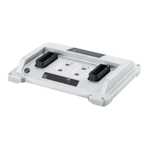
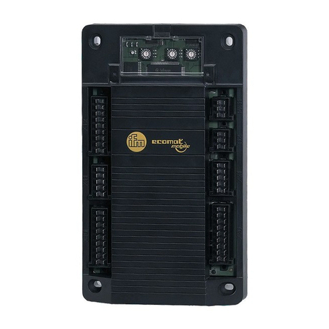
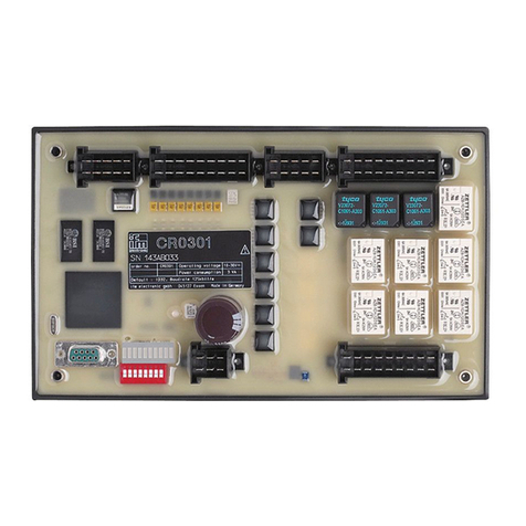
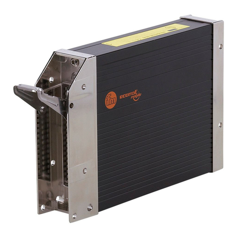
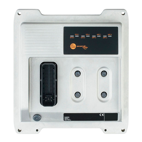
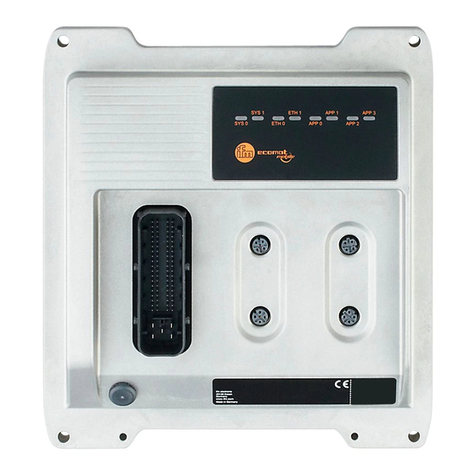
IFM ecomat 100 R 360 Series User guide

System manual
ecomat 100 type R 360

page 2
System manual ecomat 100 type R 360, April 1999
Guarantee
This manual was written with the utmost care. However, we cannot assume any guarantee for the
contents.
Since errors cannot be avoided despite all efforts we appreciate any comment.
We reserve the right to make technical alterations to the product which might result in a change of
contents of the manual.

page 3
1. General 5
1.1. Safety instructions 5
1.2. Function and features 6
1.3. Controller configuration 7
1.4. Technical data 8
1.5. Mounting of the modules 12
1.6. Electrical connection of the modules 12
1.7. Fusing of the controller modules 12
2. The monitoring function 15
2.1. Hardware setup 15
2.2. Function of the monitoring concept 16
3. Unit I/O configuration 17
3.1. Bidirectional and diagnostic I/O channels 17
3.1.1. Bidirectional inputs/outputs 17
3.1.2. Outputs with diagnostic functions 18
3.2. Fast inputs 19
3.3. The software control configuration 19
3.4. Wiring 19
4. States and operating system 21
4.1. Operating modes 21
4.2. Status LED 22
4.3. Loading the operating sytem 22
4.3. Operating modes 25
5. Error codes and error classes 27
5.1. Reaction to system error 27
6. CAN in the ecomat R 360 29
6.1. Technical specifications 29
6.2. Exchange of data via CAN 29
6.3. CAN errors and error handling 31
6.4. The physical CAN link 33
6.5. General remarks on the CAN utilization 36
6.6. Description of the CAN function blocks 38
6.7. CANopen in the ecomat R 360 44
6.8. The ecomat R 360 as CANopen slave 48
6.9. The ecomat R 360 as CANopen master 59
6.10. Functions for CANopen I/O modules from ifm electronic 78

page 4
7. PWM in the ecomat R 360 87
8. Fast counters in the ecomat R 360 97
9. Other functions in the ecomat R 360 101
9.1. Software reset 101
9.2. Save data in memory and read 102
9.3. Use of the serial interface 106
9.4. Reading the system time 110
9.5. Processing of variables 112
10. Closed-loop control functions 113
10.1. Adjustment rule for a controller 115
11. Functions of the ecomat tdm R 360 127
11.1. Data exchange and variable definition 129
11.2. Setting and resetting of pictures and messages 134
11.3. The unit status and the LEDs 137
11.4. Unit control 144
Annex 1. Address allocation ecomat R 360 147
Annex 1.1. Complete overview 147
Annex 1.2. Inputs 149
Annex 1.3. Outputs 150
Annex 1.4. Allocation outputs – short-circuit and wire-break bits 151
Annex 1.5. The flag range in the ecomat R 360 152
Annex 1.6. CANopen unit interface ecomat R 360 153
Annex 1.7. Object list of the ecomat R 360 154
Annex 1.7.1. Data range communication profile, index 1000 to 1FFF 154
Annex 1.7.2. Range of manufacturer-specific data, index 2000 to 5FFF 161
Annex 1.7.3. Legend to object library 161
Annex 2. Wiring 163
Annex 2.1. Type CR0015 163
Annex 2.2. Type CR0016 164
Annex 2.3. Type CR0017 165
Annex 2.4. Type CR0501 166

page 5
1. General
1.1. Safety instructions
Observe the information of the description. Non-observance of
the notes, operation which is not in accordance with use as
prescribed below, wrong installation or handling can result in
serious harm concerning the safety of persons and plants.
The instructions are for authorised persons according to the
EMC and low voltage guidelines. The controllers must be
installed and commissioned by a skilled electrician (programmer
or service technician).
This description is part of the unit. It contains texts and drawings
concerning the correct handling of the controller and must be
read before installation or use.
If the unit is not supplied by the mobile on-board system (24V
battery operation) it must be ensured that the external voltage is
generated and supplied according to the criteria for safety extra-
low voltage (SELV) as this is supplied without further measures
to the connected controller, the sensors, and the actuators.
The wiring of all signals in connection with the SELV circuit of
the unit must also comply with the SELV criteria (safe extra-low
voltage, safe electrical separation from other electric circuits).
If the supplied SELV voltage as an external connection to
ground (SELV becomes PELV) the responsibility lies with the
user and the respective national regulations for installation must
be complied with. All statements in these operation instructions
refer to the unit the SELV voltage of which is not grounded.
The terminals may only be supplied with the signals indicated in
the technical data or on the unit label and only the approved
accessories of ifm electronic gmbh may be connected.
The unit can be operated within a wide temperature range
according to the technical specification indicated below. Due to
the additional self-heating the housing walls can have high
perceptible temperatures when touched in hot environments.

page 6
In the case of malfunctions or uncertainties please contact the
manufacturer. Tampering with the units can lead to
considerable risks for the safety of persons and plant. It is not
permitted and leads to the exclusion of any liability and warranty
claims.
1.2. Function and features
The controller modules ecomat 100 series R 360 (in the
following text ecomat R 360) are for the user under harsh
operating conditions (e.g. extended temperature range, strong
vibration, intensive EMC interference). They are thus suited for
direct mounting into machines in mobile and rugged
applications. Due to their specification the inputs and outputs
are especially rated for this use. Integrated hardware and
software functions (operating system) offer high protection of
the machine.
The controller ecomat R 360 is approved for safety-
relevant tasks in the field of safety of persons if the
corresponding system test routines are integrated in the
operating system and the application software. The final
classification and the release of the system (hardware and
software) can only be done by the proper supervisory
organisations. The programmer has to obtain information
about the special characteristics of the hardware and
software in the additional documentation which can be
obtained on request.
ifm electronic gmbh
Teichstr. 4
D 45127 Essen
Tel.: 0201 / 2422-0
Fax: 0201 / 2422-303
The application software can easily be created by the user with
the ecolog 100plus software.
All software functions and programming processes
described in this documentation refer to the ecolog 100plus
programming software the knowledge of which is required
for this description.
The user also has to observe the software versions (especially
the operating system of the R 360 and the function libraries) that
is used. Software levels are marked by suffixed letters in
alphabetic order in the file names (e.g. CR0015_B.DL or TDM-
A.LIB). When revising existing application projects the user
should find out about incompatibilities between the old and the
new versions.

page 7
The user is responsible for the safe functioning of the
application programs which he creates himself. If
necessary, he must additionally obtain an approval
according to the corresponding national regulations by the
relevant testing and supervisory organisations.
1.3. Controller configuration
The ecomat R 360 is a customer or application-specific concept
for series use which means that the control modules have the
optimum configuration to the application. If necessary, special
functions and special hardware solutions can be accomplished.
In general: All descriptions and explanations in this manual
are generally applicable to the controller system ecomat R
360. The appropriate controller configuration for the unit in
use is to be loaded in the programming system (article
number of the unit, CRnnnn = file name controller
configuration CRnnnn_X).
Before using the controller modules you need to check the
availability of certain functions, hardware options, inputs and
outputs are available in the hardware.

page 8
1.4. Technical data
Housing: closed, screened metal housing with flange fastening
Housing dimensions: 225 x 153 x 43 mm (WxHxD), without connector
240 x 153 x 43 mm (WxHxD), with connector
Mounting position: preferably vertical, alternatively horizontal
Connection of the unit: 55-pin connector, latched, protected against reverse polarity,
AMP pr Framatom type housing with crimp connection contacts
AMP junior timer 0.5/2.5 mm2
Operating temperature: -30°C ... +75°C
Storage temperature: -40°C ... +90°C
Protection rating: IP67 (protection for connector, depending on cable version)
Protection class: III
Air humidity: ≤90% rel. air humidity, non-condensing
Supply voltage: UB nominal 12 or 24 V DC (-10% ... +25%)
See type label (reverse polarity protection through connector)
residual ripple: ≤1.5 Vpp, f ≤ 50Hz
reset in case of undervoltage 12 V unit: ≤ + 9.6 V
reset in case of undervoltage 24 V unit: ≤ +12.0 V
overvoltage 12 V unit: ≤ + 17.5 V for t ≤ 10s
overvoltage 24 V unit: ≤ + 36.0 V for t ≤ 10s
Power consumption: ≤ 400 mA, without external load
Processor: CMOS microcontroller C 167C
Display: two-colour-LED red/green for indication of status and error
Device monitoring: 8-bit microcontroller to monitor the C 167C (extended watchdog
function)
check sum test for program and system
under and overvoltage monitoring, excess temperature
monitoring
Memory: 256 kByte program memory
64 kByte data memory (volatile)
with 1 kByte data memory protected against voltage failure
(256 Byte auto-save)
Interface: CAN, Version 2.0 B (ISO/DIS-11898), 10 ... 1000 kBaud
protocol: CANopen or free communication profile
device class: CANopen master/slave; CAN: FullCAN
serial interface RS 232 C, 9,6 kBaud
number of participants: 2 (master/slave)

page 9
Binary input
Low-Side (PNP):
Inputs IX0.0 ... IX0.7: switch-on level UB≥10 V, I ≥3.3 mA
switch-off level UB≤5 V, I ≤1.7 mA
input frequency 50 Hz
Inputs IX0.8 ... IX0.39: switch-on level 0.6 UB... 0.8 UB, I ≥6.7 mA
switch-off level 0.4 UB... 0.2 UB, I ≤1.7 mA
input frequency 50 Hz
Pulse inputs IX0.12 ... IX0.15: input frequency 50 kHz
Pulse inputs IX0.20 ... IX0.23: input frequency 50 kHz
Binary input
High-Side (NPN):
Inputs IX0.8 ... IX0.39: switch-on level 0.05 UB... 0.04 UB, I ≥7.7 mA
switch-off level 0.30 UB... 0.40 UB, I ≤5.1 mA
input frequency 50 Hz
Analog input
Low-Side:
Inputs IW9 ... IW16: input voltage +0 ... 10 V
input impedance ≥50 kΩ
resolution 10 Bit
accuracy ≤ ± 1.0 % FS

page 10
Binary output
High-Side (PNP):
Outputs QX0.0 ... QX0.23: semiconductor output; short-circuit and overload protection,
diagnostic capability as an option
switching voltage 10 ... 17 V (12 V DC); 11 ... 32 V (24 V DC)
switching current 50 mA ... 2.5 A
overload current 5 A
sum current 10 A (per 8 outputs)
output frequency max. 100 Hz (depending on the load)
Outputs QX0.00 ... QX0.07 special specification as PWM output
output frequency max. 1000 Hz
PWM mark/space ratio 1 ... 99%
resolution depending on the PWM frequency
Binary output
Low-Side (NPN):
Outputs QX0.0 ... QX0.23: semiconductor output; short-circuit and overload protection,
diagnostic capability as an option
switching voltage 10 ... 17 V (12 V DC); 11 ... 32 V (24 V
DC)
switching current 50 mA ... 2.5 A
overload current 5 A
sum current 10 A (per 8 outputs)
output frequency max. 100 Hz (depending on the load)

page 11
Input Test: For the duration of the test operation (e.g. programming) the
connection needs to be connected to UB(supply).
For ”RUN” operation the input needs to be disconnected from
UB(supply).
Output Error (pin 13): semiconductor output; short-circuit and overload protection
switching voltage 10 ... 17 V (12 V DC); 11 ... 32 V (24 V DC)
switching current 10 mA ... 100 mA
overload current 0.5 A
Relay output: internal relay output
used in series with (max. 12 outputs the power supply of which
is interrupted on detection of an error by hardware or user
program
On principle, the unit should be switched load-free.
switching current 100 mA ... 15 A
overload current 20 A
no. of switching
operations (load-free) ≥ 106
response time ≤ 3 ms
Housing drawing:

page 12
1.5. Mounting of the modules
In order to expose the controller modules to the minimum
mechanical stress they should preferably be mounted
horizontally or vertically on the mounting panel. The module
must be fixed with four screws to DIN 7500 or DIN 7984 (M5 x
L).
If possible, the modules should be mounted in such a way that
the cable entry of the plug points downwards.
1.6. Electrical connection of the modules
Before commissioning it must be ensured that the following pins
must/can be connected to the corresponding potentials.
To guarantee the electrical interference protection of the
controller modules, the housings must be connected to
the ground of the vehicle.
1.7. Fusing of the controller modules
In order to protect the whole system (cabling and controller) the
individual circuits must be fused accordingly, taking into account
the total current of 10 A of the individual output modules (max. 8
outputs – e.g. QX0.08 ... QX0.15).
Designation Pin No. Potential
Supply voltage 23 (VBBS) + 24 V DC
Ground 01 (GNDS) GND
Analog ground 12 (GNDA) GND
Supply voltage
outputs High-Side
without monitoring relay
05 (VBBo) + 24 V DC
Supply voltage
outputs High-Side
with monitoring relay
34 (VBBR) + 24 V DC
Supply voltage
outputs Low-Side
without monitoring relay
15 (GNDo) GND
Test input,
programming mode 24 (Test) + 24 V DC
Test input, operating mode 24 (Test) open
Programming interface RS 232 06 (RxD) Pin 03, PC 9pin SUB-D
07 (TxD) Pin 02, PC 9pin SUB-D
33 (CM5) Pin 05, PC 9pin SUB-D
CAN interface 14 (CANH) CANH further participant
32 (CANL) CANLfurther participant
33 (CM5) GND further participant

page 13
If an output terminal receives current externally, e.g. for
bidirectional inputs and outputs, the output rail must not
be floating (i.e. open-circuit)
Reason The supply voltage is fed back to the output rail via the
integrated protective diode in the output. If a second output
connected to the same potential is switched, the load of this
output is fed through the transistor of the first output thus
causing the first output to overload and fail.
This needs special attention when unit and output voltage
supply are fused separately and when the output rail VBBR is
switched off by the software via the integrated relay. If
necessary, the supply voltage should be monitored via the
appropriate hardware and software measures.

page 14

page 15
2. The monitoring function
The safe operation of the controller outputs is ensured by the
monitoring function.
2.1. Hardware setup
The relay is triggered on two channels via the µcontroller. For
this purpose the negative channel is triggered by means of an
AND link of the watchdog signal (internal µcontroller monitoring)
and the RELAY bit with a semiconductor switch. The positive
channel is only triggered by means of the ERROR bit via a
semiconductor switch. In the activated state the outputs to be
disconnected (max. 12) are connected to the supply voltage via
the relay contact (not forced)
In addition the output signal of the semiconductor switch has the
logical effect of a release signal for all outputs. These outputs
are only switched externally after the RELAY bit has been set.
Therefore the RELAY bit has to be set even if there is no
RELAY integrated in the hardware.
Schematic of the monitoring concept.

page 16
2.2. Function of the monitoring concept
While the program is running the monitoring relay is under the
complete control of the software user. A parallel contact from
the safety circuit for example can be evaluated as an input and
the monitoring relay can be switched off. For further safety the
appropriate national regulations must be applied.
If a µcontroller error occurs while the program is running the
watchdog signal switches the relay off so that important parts of
the plant can be protected.
When creating the program the programmer has to make
sure the program is left in a safe state (so that automatic
operation is reset) in the case of an internal (e.g. watchdog)
or external error (e.g safety circuit). For this purpose the
outputs in question have to be switched off by software.
If an output to be monitored is permanently switched and the
contact of the monitoring relay is welded it is not possible to
switch off this output. However, since the relay is always
switched load-free in normal operation, the contact wear is very
low.

page 17
3. Unit I/O configuration
The unit I/O configurations described in the annex are available
as standard units (ex stock). They cover the required
specifications for most of the applications.
Depending on the customer’s requirements for series
applications it is possible to realise other configurations, e.g.
regarding the arrangement of inputs and outputs and the design
of the analog channels.
The software functions described in this documentation only
apply to standard configurations. For customer-specific units
the specific hardware versions and additional software
description (additional documentation) have to be observed.
3.1. Bidirectional and diagnostic I/O channels
The inputs/outputs of the R 360 can be designed as
bidirectional input/output channels or for readback functions
(diagnosis, wire-break monitoring, short-circuit monitoring). At
the terminal the input and output or the output with the
corresponding readback channel (readback input) are available
simultaneously.
For safety-relevant applications outputs with readback
function (diagnostic outputs) are to be used.
3.1.1. Bidirectional inputs/outputs
The connection can be used as an input or an output. The input
can be read via the software at any time.

page 18
This function is based on the condition that in the controllers
high-side outputs are combined with low-side inputs or low-side
outputs are combined with high-side inputs so that no conflicts
can occur, i.e. short circuit via the switched output transistor and
closed switch at the input.
The block circuit diagram shows:
• The load connected to the output can also be triggered
manually via the switch. The position of the switch can only
be detected when the output is blocked.
(Insert suppressor circuit via the load)
• Short-circuit detection (overload) is also possible via the
input channel when the switch is open. The LOW (logic 0) is
read in when the output is switched.
In the case of a short circuit (overload) the output transistor
switches off automatically. For safety reasons it does not
switch on again automatically when the short circuit has been
removed. The output has to be switched off and then on
again via the software
• Wire-break detection is not possible with this input/output
configuration.
3.1.2. Outputs with diagnostic functions
The connection can be used as an input as well as an output.
The input can be read at any time via the software.
This function is based on the condition that in the controller
high-side outputs are combined with high-side inputs or low-side
outputs with low-side inputs.

page 19
The block circuit diagram shows:
• Short-circuit detection (overload) is possible via the input
channel. When the output is switched the LOW (logic 0) can
be read in.
The output transistor automatically switches off in the case of
a short circuit/overload. For safety reasons it does not switch
on again automatically. Therefore it has to be switched off
and then switched on again.
• Wire-break detection is possible via the input channel. When
the output is blocked HIGH (logic 1) is read in as the resistor
Ripulls the output to HIGH potential (VBB). Without the wire
break the low-resistance load (RL< 10 kΩ) would force
(logic 0) LOW.
3.2. Fast inputs
In the controller modules the standard unit configurations have
an input frequency up to 50 kHz via 8 fast count/pulse inputs. If
e.g. mechanical switches are connected to these inputs, contact
bouncing might cause wrong signals in the controller. These
"error signals" have to be filtered out with the application
software, if required (see example program).
3.3. The software control configuration
For each hardware configuration the corresponding software
control configuration has to be loaded in the programming
system. For the programming system it represents the interface
to the hardware.
The software control configuration also provides the user with all
important system and error flags. Depending on the application
program they have to be processed and evaluated. They can be
accessed with their symbolic names or the IEC addresses.
3.4. Wiring
The wiring shown in the annex describes the standard unit
configurations. The wiring helps to assign the input and output
channels to the IEC 1131 addresses and the unit terminals.

page 20
Labelling of the input/output channels:
12 pin number
GNDApin description
30 pin number
%IX0.07 IEC address for a binary input
BL hardware design of the input
(here binary low-side)
47 pin number
%QX0.03 IEC address for a binary output
BH/PH hardware design of the output
(here binary high-side or PWM high-side)
The abbreviations have the following meanings:
A analog input
BH binary input/output, high-side
BL binary input/output, low-side
PH PWM output, high-side
PL PWM output, low-side
IH pulse/counter input, high-side
IL pulse/counter input, low-side
R readback channel for an output
Allocation of the input/output channels:
Depending on the unit configuration an input and/or output is
available at a unit terminal.
Channels that can be used as inputs and outputs
simultaneously (bidirectional inputs/outputs) are highlighted
12 GNDA
30 %IX0.07 BL
47 %QX0.03 BH/PH
Table of contents
Other IFM Controllers manuals

IFM
IFM CR720S User manual
IFM
IFM Ecomat 300 AS-i Series Application guide

IFM
IFM AC1403 Application guide

IFM
IFM ecomatController User manual

IFM
IFM CabinetLine AE3100 User manual

IFM
IFM ecomatController CR0708 User manual

IFM
IFM Ecomat 300 AC1318 Application guide

IFM
IFM Ecomat 300 AC1307 Application guide

IFM
IFM Ecomat 300 AC1355 Application guide

IFM
IFM CR1200 User manual

IFM
IFM SmartPLC DataLine AC1423 Application guide
IFM
IFM CR720S User manual

IFM
IFM AC1433 Application guide

IFM
IFM CR710S User manual

IFM
IFM CR7132 User manual

IFM
IFM Ecomat 100 Mobile CR0301 Owner's manual

IFM
IFM AE1300 User manual

IFM
IFM ecomat100 CS0015 User manual
IFM
IFM CR7032 User manual

IFM
IFM Ecomat 100 CR0303 Application guide