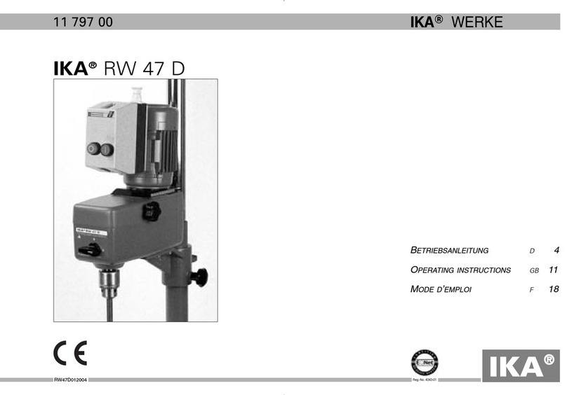
IKA RW 16 basic User manual

BETRIEBSANLEITUNG
D
5
OPERATING INSTRUCTIONS
GB
10
MODE D’EMPLOI
F
15
INSTRUCCIONES DE MANEJO
E
20
HANDLEIDING
NL
25
INSTRU IONI PER L’USO
I
30
DRIFTSANVISNING
S
35
DRIFTSINSTRUKS
DK
40
KÄYTTÖOHJE
N
45
DRIFTSVEJLEDNING
SF
50
Ο∆ΗΓΙΕΣ ΛΕΙΤΟΥΡΓΙΑΣ
GR
55
INSTRUÇÕES DE SERVIÇO
P
60
IKA®WERKE
RW160995EU
IKA RW 16 basic
25 510 00
Reg.-No. 4343-01
IKAIKA
®®
All manuals and user guides at all-guides.com

all-guides.com

2 RW160995EU
CE-KONFORMITÄTSERKLÄRUNG
D
ir erklären in alleiniger Verantwortung, daß dieses Produkt den Bestimmungen der
Richtlinien 89/336E G und 89/392E G entspricht und mit den folgenden
Normen und
norminativen Dokumenten übereinstimmt: EN 61 010; EN 50 082; EN 55 014; EN 60 204;
EN 60 555; EN 292 und EN 414.
CE-DECLARATION OF CONFORMITY GB
e declare under our sole responsibility that this product corrosponds to the regulati-
ons 89/336EEC and 89/392EEC and conforms with the standards or standardized docu-
ments
EN 61 010; EN 50 082; EN 55 014; EN 60 204: EN 60 555; EN 292 and EN 414.
DÉCLARATION DE CONFORMITÉ CE F
Nous déclarons sous notre propre responsabilité que se produit est conforme aux
réglementations 89/336CEE et 89/392CEE et en conformité avec les normes ou docu-
ments normalisés suivant
EN 61 010; EN 50 082; EN 55 014; EN 60 204: EN 60 555; EN
292 et EN 414.
DECLARACION DE CONFORMIDAD DE CE E
Declaramos por nuestra responsabilidad propia que este produkto corresponde a las
directrices 89/336CEE y 89/392CEE y que cumple las normas o documentos normati-
vos siguientes:
EN 61 010; EN 50 082; EN 55 014; EN 60 204; EN 60 555;
EN 292 y EN 414.
CE-CONFORMITEITSVERKLRING NL
ij verklaren in eigen verantwoordlijkheid, dat dit produkt voldoet ann de bepalingen
van de richtlijnen 89/336EEG and 89/392EEG en met de volgende normen
of normatie-
ve dokumenten overeenstemt: EN 61 010; EN 50 082; EN 55 014; EN 60 204; EN 60 555;
EN 292 en EN 414.
CE-DICHIARAZIONE DI CONFORMITÀ I
Dichiariamo, assumendone la piena responsabilità, che il prodotto è conforme alle
seguenti direttive: CCE 89/336 e CCE 89/392, in accordo ai seguenti regolamenti e
documenti:
EN 61 010; EN 50 082; EN 55 014; EN 60 204; EN 60 555; EN 292 e EN 414.
CE-KONFORMITETSFÖRKLARUNG S
Vi förklarar oss ensamt ansvariga för att denna produkt motsvarar bestämmelserna i
riktlinjerna 89/336EEG och 89/392EEG och att den överensstämmer med
följande nor-
mer eller normativa dokument: EN 61 010; EN 50 082; EN 55 014; EN 60 204;
EN 60 555; EN 292 och EN 414.
CE-KONFORMITETSERKLÆRING DK
Vi erklærer, at dette produkt öpfylder bestemmelserne i direktiverne 89/336EØF og
89/392EØF og at det er overensstemmende med følgende normer eller normgivende
dokumenter:
EN 61 010; EN 50 082; EN 55 014; EN 60 204; EN 60 555; EN 292 og EN 414.
CE-KONFORMITETSERKLÆRING N
Vi erklærer på helt og holdent eget ansvar at dette produktet er i samsvar med bestemmel-
sene i forskriftene 89/336EEG og 89/392EEG, og at de er i overensstemmelse med følgen-
de normer eller normative dokumenter: EN 61 010; EN 50 082; EN 55 014; EN 60 204; EN
60 555; EN 292 og EN 414.
CE-STANDARDINMUKAISUUSTODISTUS
SF
Ilmoitamme täysin omalla vastuullamme, että tämä tuote vastaa EU-direktiivejä 89/336EU
sekä 89/392EU ja on seuraavien normien tai ohjeasiakirjojen mukainen: EN 61 010; EN 50
082; EN 55 014; EN 60 204; EN 60 555; EN 292 sekä EN 414.
∆ΗΛΩΣΗ ΑΝ ΑΠΟΚΡΙΣΗΣ ΕΕ GR
Με την παρούσα δήλωση βεβαιώνουνε µε αποκλειστική µασ ευθύνη
τι το παρν προϊν ανταποκρίνεται στουσ κανονισµούσ των
οδηγιών 89/336 Ε.Ο.Κ. και 89/392 Ε.Ο.Κ., και τι αντιστοιχεί στισ
ακλουθεσ προδιαγραφέσ και στα ακλουθα νοµοκανονιστικά
έγγραφα ΕΝ 61 010, ΕΝ 50 082, ΕΝ 55 014, ΕΝ 60 204, ΕΝ 60 555 ΕΝ
292 και ΕΝ 414.
DECLARAÇÃO DE CONFORMIDADE DA CE P
Declaramos sob nossa responsabilidade exclusiva que este produto cor-
responde às determinações estabelecidas nas directivas 89/336 CEE e
89/392 CEE do Conselho e que está de acordo com as seguintes normas
e documentos normativos: EN 61 010; EN50 082; EN 55 014; EN 60 204; EN 60 555;
All manuals and user guides at all-guides.com

3 RW160995EU
IKA
................RW16
110
92
38
47
56
LABORTECHNIK
basic
0
A
C
B
|
Fig. 1
Z
Y
X
Fig. 2
All manuals and user guides at all-guides.com

4 RW160995EU
All manuals and user guides at all-guides.com

5
RW160995EU
Seite
Sicherheitshinweise 5
Bestimmungsgemäßer Gebrauch 6
Auspacken 6
issenswertes 6
Antrieb 6
Motorschutz,Sicherheitseinrichtungen 6
Drehzahlen 7
Inbetriebnahme 7
Montieren des Auslegers 7
Einschalten des Gerätes 7
Abtriebswelle 8
artung und Reinigung 8
Zubehör 8
Technische Daten 8
Zulässige IKA-Rührwerkzeuge 9
Angewandte Normen und Vorschriften 9
Garantie 9
Ersatzteilliste 66
Ersatzteilbild 67
Betreiben Sie das Gerät niemals mit frei rotierendem Rührwerk-
zeug. Achten Sie darauf, daß Körperteile, Haare oder Kleidungs-
stücke nicht von rotierenden Teilen erfaßt werden können. Rich-
ten Sie Ihre Aufmerksamkeit beim Einstellen der Drehzahl auf Un-
wuchten des Rührwerkzeuges und mögliches Spritzen des zu
rührenden
Mediums. Verwenden Sie eine Rührwellens
chutzeinrichtung!
Das Gerät ist nicht für Handbetrieb geeignet. Bitte beachten Sie
einschlägige Sicherheitshinweise und Richtlinien, sowie
Arbeitsschutz- und Unfallverhütungsvorschriften für den Einsatz
im Labor.
Vermeiden Sie Stöße und Schläge auf das untere ellenende
bzw. Zahnkranzfutter. Bereits kleine, nicht erkennbare Schäden
führen zu Unwucht und unrundem Lauf der elle. Sorgsame
Behandlung garantiert sicheres Arbeiten und Langlebigkeit des
Gerätes.
Unwuchten der Abtriebswelle, des Futters und insbesondere der
Rührwerkzeuge können zu unkontrolliertem Resonanzverhalten
des Gerätes und des gesamten Aufbaues führen. Dabei können
Glasapparaturen und Rührgefäße beschädigt oder zerschlagen
werden. Dadurch und durch das rotierende Rührwerkzeug kann
der Anwender verletzt werden. ird ein unruhiger Lauf des
Gerätes bemerkt, muß auf jeden Fall die Drehzahl soweit redu-
ziert werden, bis keine Laufunruhen mehr auftreten. Tauschen
Sie in diesem Fall das Rührwerkzeug gegen ein erkzeug ohne
Unwucht aus bzw. beseitigen Sie die Unwuchtursache.
Der Betrieb mit frei rotierendem ellenende ist gefährlich. Des-
halb ist aus Gründen der Sicherheit das Durchstecken des Rühr-
werkzeuges über die obere Gehäusekante hinaus nur im Stillstand
zulässig. Beim ordnungsgemäßen Betrieb muß die Gummimem-
bran immer vollständig geschlossen sein. Achten Sie darauf, daß
die elle niemals direkt in der Gummimembran
läuft und jegliche
Reibung mit rotierenden Teilen (Rührwellen) ausgeschlossen ist.
Das Gerät darf - auch - im Reparaturfall nur von einer Fachkraft
geöffnet werden. Vor dem Öffnen ist der Netzstecker zu ziehen.
Spannungführende Teile im Innern des Gerätes können auch län-
gere Zeit nach Ziehen des Netzsteckers noch unter Spannung
stehen.
Inhaltsverzeichnis
Sicherheitshinweise
All manuals and user guides at all-guides.com

Das Rührwerk R 16 basic eignet sich zum Rühren und Mischen
von Flüssigkeiten niedriger Viskosität. Es ist für den Einsatz in
Laboratorien konzipiert. Zum bestimmungsgemäßen Gebrauch
muss das Geräte an einem Stativ befestigt werden.
Bitte packen Sie das Gerät vorsichtig aus und achten Sie auf
Beschädigungen. Es ist wichtig, daß eventuelle Transportschäden
schon beim Auspacken erkannt werden. Gegebenenfalls ist eine
sofortige Tatbestandsaufnahme erforderlich (Post, Bahn oder
Spedition).
Zum Lieferumfang des Gerätes gehören: Ein R 16 basic
Rührgerät, eine Auslegerstange, eine Innensechskantschraube, ein
inkelschraubendreher und eine Betriebsanleitung.
Mit diesem Gerät haben Sie ein qualitativ hochwertiges Produkt er-
worben. Durch die handliche Form und die einfache Handhabung ist
problemloses Arbeiten gewährleistet. Das Gehäuse bietet Schutz ge-
gen
das Eindringen von Flüssigkeiten. Die verwendeten erkstoffe
und deren genaue Kennzeichnung ermöglichen und vereinfachen
das Recycling und die iederverwendung der Teile entscheidend.
Das Gerät erwärmt sich während des Betriebes. Die großzügig
gestalteten Kühlflächen bewirken möglichst gleichmäßige
Verteilung und Abstrahlung der ärme. Das zwei Meter lange
Netzkabel ermöglicht das
problemlose Arbeiten an Stativen - auch
mit hochbauenden Glasapparaturen unter Dunstabzugshauben - ohne
Verlängerungskabel. Die Präzisionsrührwelle ist als Hohlwelle ausge-
bildet und ermöglicht das Durchstecken der Rührschäfte.
Die Drehzahl des Rührwerkes R 16 basic ist elektronisch stu-
fenlos einstellbar. Dem kugelgelagerten Gleichstrommotor ist ein
laufruhiger Zahnriemenantrieb nachgeschaltet. Der Motor wird
mittels eines prozessorgesteuerten Drehzahlreglers durch eine
pulsweitenmodulierte Spannung (P M) angesteuert. Die gesam-
te Antriebseinheit arbeitet wartungsfrei.
Das Gerät ist für Dauerbetrieb geeignet. Der Motorstrom ist elektro-
nisch begrenzt. Das Gerät ist blockier - und überlastsicher. Durch
einen Sicherheitskreis wird der Motor im Störfall über ein Relais sofort
blei-
bend ausgeschaltet.
Um das Gerät nach einem Störfall wieder in Betrieb zu nehmen, betäti-
gen Sie bitte den Netzschalter. Sollte das Gerät weiterhin ohne
Funktion sein,
wenden Sie sich bitte an unseren Service.
6 RW160995EU
Auspacken
Antrieb
Wissenswertes
Motorschutz; Sicherheitseinrichtun en
Bestimmun s emäßer Gebrauch
All manuals and user guides at all-guides.com

all-guides.com

Die Drehzahl wird mit dem frontseitigen Drehknopf (A) eingestellt.
Die Skala von 1 bis 10 entspricht einem Drehzahlbereich der
Abtriebs-welle von 40 bis 1200 Umdrehungen pro Minute unter
Nennlast. Im Leerlauf beträgt die Drehzahl bei Maximalstellung des
Drehknopfes (Rechtsanschlag) 1600 Umdrehungen pro Minute, bei
Minimalstellung des Drehknopfes (Linksanschlag) 0 Umdrehungen
pro Minute. Bei prozessbedingt zunehmender Viskosität fällt die
Drehzahl geringfügig ab. Nimmt die Viskosität hingegen z.B. durch
Zugabe dünnflüssiger Medien ab, so erhöht sich die Drehzahl
etwas. Durch entsprechendes Nachstellen des Drehknopfes kann
dies in beiden Fällen ausgeglichen werden, sofern das Dreh-
moment nicht das maximale Drehmoment übersteigt. Beachten
Sie, daß Schwankungen der Netzspannung innerhalb der zulässigen
Toleranzen auch geringe Schwankungen der Drehzahl bewirken.
Das Rührwerk muß zum bestimmungsgemäßen Gebrauch mit
einer Kreuzmuffe (z.B. R181) an einem stabilen Stativ (z.B. R1822)
befestigt werden. Der Rührbehälter sollte aus Sicherheitsgründen
immer mit einem Spannhalter (z.B. RH1) fixiert sein.
Montagebild siehe (Fig. 2)
Die Auslegerstange (X) hat an einem Ende einen Absatz mit einer
Querbohrung. Mit diesem Ende wird die Auslegerstange in die
Bohrung an der Rückseite des Gerätes gesteckt. Dabei muß die
Querbohrung der Auslegerstange nach oben zeigen. Sie ist mit der
Bohrung in der Befestigungsrippe auf der Rückseite des Gerätes in
eine Flucht zu bringen. Drücken Sie dazu den Ausleger bis zum
Anschlag in die Bohrung. enden Sie hierbei bitte keine Gewalt
an. Sollte sich der Ausleger nur schwer einführen lassen, kann
leichtes Einölen Abhilfe schaffen. Die Innensechskantschraube (Y)
zur Befestigung wird von oben in die Bohrung des Gehäuses
gesteckt. Mit dem inkelschraubendreher (Z) wird die Schraube
festgeschraubt. Prüfen Sie den Festsitz des Auslegers.
Durch Vibration kann sich die Schraube lösen. Überprüfen Sie des-
halb zur Sicherheit von Zeit zu Zeit die Befestigung des Auslegers.
Ziehen Sie gegebenenfalls die Innensechskantschraube nach.
Sie können die Innensechskantschraube auch mit einem für die
erkstoffpaarung geeigneten Kleber sichern, haben dann jedoch
keine lösbare Verbindung mehr.
Überprüfen Sie, ob die auf dem Typenschild angegebene Spann-
ung mit der verfügbaren Netzspannung übereinstimmt. Die verwen-
dete Steckdose muß geerdet sein (Schutzleiterkontakt). enn
diese Bedingungen erfüllt sind, ist das Gerät nach Einstecken des
Netzsteckers betriebsbereit. Andernfalls ist sicherer Betrieb nicht
gewährleistet oder das Gerät kann beschädigt werden.
Durch drücken des Netzschalters (B) in Stellung „I“beginnt das
Gerät zu laufen. Eine grüne Kontrolleuchte (C) signalisiert den
Betriebszustand ‘EIN’.
Bei Inbetriebnahme des Gerätes beginnt die Abtriebswelle mit der
zuletzt eingestellten Drehzahl zu laufen. Überprüfen Sie daher vor
dem Einschalten die Stellung des Drehknopfes. Vergewissern Sie
sich auch, daß die eingestellte Drehzahl für den gewählten
Versuchsaufbau unbedenklich ist. Im Zweifelsfall stellen Sie den
Drehzahlknopf (A) auf die kleinste Drehzahl (linker Anschlag).
7
RW160995EU
Drehzahlen
Inbetriebnahme
Montieren des Ausle ers
Einschalten des Gerätes
All manuals and user guides at all-guides.com

Spannfutter und Abtriebswelle gestatten das Einspannen und
Durchstecken aller handelsüblichen Rührwerkzeuge bis 10mm
Durchmesser. Die Öffnung an der Gehäuseoberseite ist mit einer
geschlitzten Gummimembran verschlossen. Es ist jedoch mög-
lich, Rührschäfte z.B. beim Behälterwechsel über die Gehäuse-
oberkante hinauszuschieben.
enn es - bedingt durch die Anordnung der Apparatur - notwen-
dig ist, das Schaftende während des Betriebes über die obere
Gehäusekante
stehen zu lassen, so ist die Gummimembran zu
entfernen. Stattdessen muß eine als Zubehör erhältliche Rührwel-
lenabdeckung auf das Gehäuse gesteckt werden. ird die
Rührwellenabdeckung wieder entfernt, ist die Gummimembran
wieder in die Gehäuseöffnung zu drücken, damit diese verschlos-
sen ist. Nur so gewährleisten Sie sicheres Arbeiten und verhin-
dern das Eindringen von Medien in das Gerät.
Beachten Sie hierzu den Abschnitt „Sicherheitshinweise !“
Das Rührwerk arbeitet wartungsfrei. Es unterliegt lediglich der
natürlichen Alterung der Bauteile und deren statistischer
Ausfallrate.
Bei Ersatzteilbestellungen geben Sie bitte die auf dem
Typenschild angegebene Fabrikationsnummer, den Ger te-
typ sowie die Bezeichnung des Ersatzteiles an.
Bitte senden Sie nur Geräte zur Reparatur ein, die gereinigt und
frei von gesundheitsgefährdenden Stoffen sind. Für die Reinigung
sind ausschließlich asser mit einem tensidhaltigen aschmittel-
zusatz oder bei stärkerer Verschmutzung Isopropylalkohol zu ver-
wenden.
R 1822 Plattenstativ RH 1 Spannhalter
R 181 Kreuzmuffe FK 1 Flexible Kupplung
DZM 1 Drehzahlmesser; RLS 8 x 33
Drehzahlbereich unter Nennlast: min
-1 40-1200
max. Drehmoment Rührwelle:
Ncm 40
zul. Einschaltdauer: %100
Drehzahleinstellung:
Drehzahlsteller mit Pulsweitenmodulator
Drehzahlanzeige:
:
Skala am Drehknopf
Nennspannung:
VAC
230±10%EURO
VAC
115±10%USA
Frequenz: Hz 50 / 60
Aufnahmeleistung: W75
Abgabeleistung: W55
Leistung an der Rührwelle: W53
Gesamtwirkungsgrad: 0,71
Schutzart nach DIN 40 050: IP42
Überspannungskategorie: II
Verschmutzungsgrad: 2
Schutz bei Überlast: el. Strombegrenzung
Sicherungen (auf Netzplatine): A4 T (IKA-Ident-Nr. 25 851 00)
8 RW160995EU
Abtriebswelle Zubehör
Wartun und Reini un
Technische Daten
Schutzmaßnahme: 0
Klasse Schutzeinrichtung Empfohlene Verwendung
0 Kein zusätlicher Schutz
Anwendung nur für Geräte, bei
denen ein Versagen der Regelung
keine Gefährdung
mit sich bringt.
Der Betriebszustand ist in regelmäßigen Abständen zu überwachen.
All manuals and user guides at all-guides.com

Antrieb (wartungsfrei) :
Gleichstrommotor mit 1stufigem Zahnriementrieb
Umgebungstemperatur: °C +5 bis+40
Umgebungsfeuchte: (Rel.) %80
Betriebslage:
am Stativ, Spannfutter nach unten gerichtet
maximale Rührmenge asser: ltr 10
für Viscosität: LV
Spannfutter-Spannbereich: mm 0,5 -10
Hohlwelle innen ø: mm 11
Ausleger: mm 13x160lang
Gehäuse: Al-Druckguß, thermoplast.Kunststoff
Abmessungen ohne Ausleger:
mm (BxTxH)
80x190x175
Gewicht mit Ausleger und Spannfutter:
kg 2,8
Drehzahlabweichungen:
Einstellgenauigkeit: %10
bei Belastung: %0 Last nmax= 1600 min-1 (Soll)
%100 Last nmax= 1200 min-1 (Soll)
Ma . Drehzahl 1/min
R1342 Propellerrührer 4fl 2 000
R1381 Propellerrührer 3fl 2 000
R1382 Propellerrührer 3fl 2 000
R1389 Propellerrührer 3fl PTFE 800
R1352 Zentrifugalrührer 2 000
R1311 Turbinenrührer 2 000
R1312 Turbinenrührer 2 000
R1335 Knetrührer 2 000
R1330 Ankerrührer PTFE 1 000
Angewandte EU-Richtlinien
EMV-Richtlinie: 89/336/E G
Maschinen-Richtlinie: 89/392/E G
Aufbau nach folgenden Sicherheitsnormen
EN 61 010-1 / VDE 411-1 EN 292-1, -2
EN 50 082-1 EN 414
EN 55 014-1 IEC 1010-1
EN 60 555-2, -3 UL 3101-1
EN 60 204-1 CAN/CSA C22,2 (1010-1)
Sie haben ein Original IKA-Laborgerät erworben, das in Technik und
Qualität höchsten Ansprüchen gerecht wird.
Entsprechend den IKA-Gewährleistungsbedingungen beträgt die
Garantiezeit 12 Monate. Im Garantiefall wenden Sie sich bitte an
Ihren Fachhändler. Sie können aber auch das Gerät unter Beifügung
der Lieferrechnung und Nennung der Reklamationsgründe direkt an
unser erk senden. Frachtkosten gehen zu Ihren Lasten.
9
RW160995EU
Viskosität mPa · s
VLV very low viscosity 0 .......... 100 asser bis dünn-
flüssiges Öl
LV low viscosity 100....... 1000 dünnflüssiges Öl bis
dickflüssiges Öl
MV medium viscosity 1000.. 10000 dickflüssiges Öl bis
Honig bei ca. 20 °C
HV high viscosity 10000 100000 Honig bei ca. 20 °C
bis Druckfarben
Zulässi e IKA-Rührwerkzeu e
An ewandte Normen und Vorschriften
Garantie
All manuals and user guides at all-guides.com

Page
Safety instructions 10
Correct use 11
Unpacking 11
Useful details 11
Drive 11
Motor protection, safety devices 11
Speed 12
Commissioning 12
Mounting extension arm 12
Switching apparatus on 12
Output shaft 13
Maintenance and cleaning 13
Accessories 13
Technical data 13
Permitted IKA stirrer tools 14
Associated standards and regulations 14
Guarantee 14
Spare parts list 66
Spare parts diagram67
Never operate the equipment with the stirrer tools rotating
freely. Ensure that parts of the body, hair or items of clothing
cannot be trapped by the rotating parts. Pay attention when
setting the speed to any imbalance of the stirrer tools and
possible spraying of the medium to be stirred. Use a stirrer shaft
protection device!
The equipment is not suitable for manual operation. Please follow
the relevant safety instructions and guidelines, and occupational
health and safety regulations for use in the laboratory.
Avoid knocks and impacts on the lower end of the shaft and the
chuck gear teeth. Even minor, invisible damage can lead to im -
balance and uneven shaft action. Careful handling guarantees
safe working and the long life of the equipment.
Imbalance of the output shaft, the chuck and in particular the
stirring tools can lead to uncontrolled resonant vibrational
behaviour of the equipment and the whole assembly. Glass
apparatus and stirrer containers can be damaged or shattered by
this. It can cause injury to the operator, as can the rotating stirring
tool. If vibration of the equipment is noticed, the speed must be
reduced immediately in all cases until no more vibration occurs.
In this case exchange the stirring tool for one without imbalance
or remedy the cause of the imbalance.
Operating with a freely rotating shaft end is dangerous. Therefore
for safety reasons the stirrer tool is permitted to project over the
upper edge of the housing only when the machine is not running.
For correct operation, the rubber diaphragm must always be com-
pletely closed. Take care to ensure that the shaft never runs
directly in the rubber diaphragm and any friction with rotating
parts (stirrer shafts) is excluded.
The machine may only be opened by trained specialists - even
during repairs. The machine is to be unplugged from the mains
before opening. Live parts inside the machine may still be live for
some time after unplugging from the mains.
10 RW160995EU
CONTENTS
Safety instructions
All manuals and user guides at all-guides.com

The basic R 16 stirrer is suitable for stirring and mixing fluids
with low viscosity. It is designed for use in laboratories. For
correct use, the equipment must be secured to a fixed object.
Please unpack the machine carefully and inspect for damage. It is
important that any transit damage should be noted at the time of
unpacking. In certain circumstances it may be necessary to in -
vestigate immediately (post, rail or freight forwarder). The guaran -
tee covers: One R 16 stirring machine, one extension arm, one
hexagonal socket screw, one hexagon socket offset screw key
and operating instructions.
In buying this machine you have chosen a high quality product.
Ease of use is guaranteed with its handy shape and simple ope-
ration. The housing offers protection against ingress of liquids.
The materials used and their precise identification make recycling
possible and simple, and enables re-use of the parts. The
generously proportioned cooling surfaces enable distribution and
transference of heat to be as even as possible. The two metre
long mains lead makes it possible to work on stands - even with
high glass apparatus under vapour extraction hoods - without
extension leads. The precision stirrer shaft is designed as a hol-
low shaft to allow the stirrer shanks to be in serted.
The speed of the R 16 basic stirrers can be infinitely adjusted
by electronic means. The ball bearing equipped DC motor has a
quiet synchronous belt drive. The motor is controlled via a com-
puter-controlled speed regulator using pulse-width modulated
voltage (P M). The whole drive unit is main tenance-free.
The machine is suitable for continuous operation. The motor cur-
rent is electronically limited. The machine has an anti-stall and
anti-overload system. If a fault occurs, a safety circuit immediate-
ly switches off the motor permanently via a relay.
To start the machine again after a fault, please operate the mains
switch. If the machine still does not work, please contact our
Service department.
11
RW160995EU
Unpackin
Drive
Useful facts
Motor protection; safety devices
Correct use
All manuals and user guides at all-guides.com

all-guides.com

The speed is set using the front knob(A). The scale from 1 to 10
corresponds to a speed range for the output shaft of 40 to 1200
rpm under nominal load. ith no load the speed at maximum set-
ting of the knob (right position) is 1600 rpm, at minimum setting
of the knob (left position) 0 rpm. If viscosity increases due to the
process, the speed reduces gradually. If, however, the viscosity
is reduced by eg the addition of thinning agents, the speed increa-
ses somewhat. This can be balanced out in both cases by re-set-
ting the knob accordingly, provided torque does not exceed maxi-
mum torque. Please note that fluctuations in mains voltage wit-
hin the permitted tolerances may also cause minor fluctuations in
speed.
For correct use, the stirrer must be secured to a stable object
(eg R1822) with a cross-sleeve (eg R181). For safety reasons the
stirrer container should always be fixed with a tension-holder
(eg RH1).
For diagram see (Fig. 2)
The extension arm (X) has a step at its end with a cross hole. This
end is used to insert the extension arm into the hole on the back
of the machine. To do this, the cross hole in the extension arm
must point upwards. It must be brought into alignment with the
hole in the fixing rib on the back of the machine. To do this, press
the extension arm until it catches in the hole. Please do not use
force to do this. If it proves difficult to insert the extension arm,
light oiling may help. The hexagonal socket screw (Y) used for
fixing is inserted in the hole in the housing from above. The screw
is tightened using the hexagon socket offset screw key (Z).
Check that the extension arm is firmly seated. The screw may
loosen with vibration. Therefore as a precaution check from time
to time that the extension arm is still securely attached.
If necessary tighten the hexagonal socket screw.
You can also secure the hexagonal socket screw with adhesive,
but you are then unable to release the connection later
.
Check whether the voltage given on the type plate corresponds
to the available mains voltage. The socket used must be earthed
(fitted with earth contact). If these conditions have been met, the
machine is ready to operate when the mains plug is plugged in.
If these conditions are not met, safe operation is not guaranteed
and the machine could be damaged.
The machine is started by pressing the mains switch (B) into
position “l”. A green control light (C) signals the operating
condition “ON”.
During commissioning of the machine the output shaft starts to
run at the last speed set. Therefore check the setting of the con-
trol knob. Also ensure that the speed set is suitable for the test
texture selected. If in doubt, set the speed knob (A) to the lowest
speed (left-hand position).
12 RW160995EU
Commissionin
Mountin the extension arm
Speed
Switchin on the machine
All manuals and user guides at all-guides.com

The clamping chuck and output shaft permit all standard
commercial stirrer tools up to 10mm diameter to be gripped and
screwed in. The opening on the top side of the housing is closed
with a slotted rubber diaphragm. It is, however, possible for stir-
ring shafts to push out over the top edge of the housing eg during
change of container.
If it becomes necessary - depending on the layout of the equip-
ment - to allow the shaft end to project over the edge of the hou-
sing during operations, the rubber diaphragm should be removed.
Instead a stirrer shaft cover, which can be obtained as an acc -
essory, must be placed on the housing. If the stirrer shaft cover
is removed again, the rubber diaphragm must be pressed into the
housing opening again so that this is closed. This is the only way
of ensuring safe working and preventing any fluids from penetra-
ting the equipment.
Please see section ”Safety Instructions”!
The stirrer is maintenance-free. It is subject only to the natural
wear and tear of components and their statistical failure rate.
When ordering spare parts, please give the manufacturing
number shown on the type plate, the machine type and the
name of the spare part.
Please send in equipment for repair only after it has been clea-
ned and is free from any materials which may constitute a
health hazard. Only use water with a detergent additive contai-
ning a surfactant for cleaning, or for heavier soiling isopropylal-
cohol.
R 1822
Fixed plate
RH 1
Tension-holder
R 181
Cross-sleeve
FK 1
Flexible connection
DZM 1
Speedometer; RLS 8 x 33
Speed range under nominal load: min
-1 40-1200
Max. stirrer speed:
Ncm 40
Permitted switched-on time: %100
Speed setting:
Speed adjuster with pulse width modulator
Speed indicator: Scale on knob
Nominal voltage:
VAC
230±10%EURO
VAC
115±10%USA
Frequency: Hz 50 / 60
Input power: W75
Output power: W55
Output on stirrer shaft: W53
Total efficiency: 0,71
Protection type to DIN 40 050: IP42
Excess voltage category: II
Degree of pollution: 2
Overload protection: El. current limitation
Fuses (on mains plate): A4 T (IKA ident.no. 25 851 00)
13
RW160995EU
Output shaft
Maintenance and cleanin
Accessories
Technical data
Protection measures:
0
Class Protection device Recommended use
0
No additional protection
Used only on equipment where
failure of the controls does
not represent a hazard.
The operating conditions should be monitored at regular intervals.
All manuals and user guides at all-guides.com

A Drive
(maintenance-free)
: DC motor with 1-level synchronous belt drive
Environmental temp.: °C +5 to+40
Environmental humidity: %80
Operating position:
on fixed object, tension filler facing down
Max. qty. of stirred water: ltr 10
for viscosity: LV
Clamping chuck tension range: mm 0,5 -10
Hollow shaft, internal dia.: mm 11
Extension: mm 13x160long
Housing: Al diecast, thermoplast. plastic
Dimensions excl. extension: mm (BxTxH)
80x190x175
eight with extension and
clamping chuck: kg 2,8
Speed deviations:
Adjustment precision: %10
hen loaded: %0 load nmax= 1600 min-1 (nom.)
%100 load nmax= 1200 min-1 (nom.)
Ma . speed rpm
R1342 Propeller stirrer 4fl 2 000
R1381 Propeller stirrer 3fl 2 000
R1382 Propeller stirrer 3fl 2 000
R1389 Propeller stirrer 3fl PTFE 800
R1352 Centrifugal stirrer 2 000
R1311 Turbine stirrer 2 000
R1312 Turbine stirrer 2 000
R1335 Kneading stirrer 2 000
R1330 Anchor stirrer PTFE 1 000
Associated EU guidelines
EMV guidelines: 89/336/EC
Machine guidelines: 89/392/EC
Construction in accordance with the following safety standards:
EN 61 010-1 /VDE 411-1 EN 292-1, -2
EN 50 082-1 EN 414
EN 55 014-1 IEC 1010-1
EN 60 555-2, -3 UL 3101-1
EN 60 204-1 CAN/CSA C22.2 (1010-1)
You have purchased an original IKA laboratory machine which
meets the highest engineering and quality standards.
In accordance with IKA guarantee conditions, the guarantee peri-
od is 12 months. For claims under the guarantee please contact
your local dealer. You may also send the machine direct to our
works, enclosing the delivery invoice and giving reasons for the
claim. You will be liable for freight costs.
14 RW160995EU
Viscosity
mPa · s
VLV very low viscosity 0 .......... 100
water up to
thin-flowing oil
LV low viscosity 100....... 1000
thin-flowing oil up to
thick-flowing oil
MV medium viscosity 1000.. 10000
thick-flowing oil up to
honey at approx. 20 °C.
HV high viscosity 10000 100000 honey at approx. 20 °C
up to printing inks
Permitted IKA stirrer tools
Associated standards and re ulation
s
Guarantee
All manuals and user guides at all-guides.com

Page
Consignes de sécurité 15
Utilisation conforme aux prescriptions 16
Déballage 16
Particularités intéressantes 16
Commande 16
Protection du moteur, dispositifs de sécurité 16
Vitesse de rotation 17
Mise en service 17
Montage de la potence 17
Mise en marche de l’appareil 17
Arbre de sortie 18
Entretien et nettoyage 18
Accessoires 18
Caractéristiques techniques 18
Instruments agitateurs IKA autorisés 19
Normes et spécifications appliquées 19
Garantie 19
Catalogue des pièces de rechange 66
Tableau des pièces de rechange 67
Ne jamais utiliser l’appareil avec l’agitateur en rotation libre. Veillez à
ce que des corps étrangers, des cheveux ou des parties de vêtements
ne soient pas happés par des éléments en rotation. Lors du réglage de
la vitesse de rotation, soyez attentifs à l’apparition d’un balourd de
l’instrument agitateur et à la projection éventuelle de la matière à
agiter. Utilisez un dispositif de protection de l’axe d’agitation!
L’appareil n’est pas conçu pour le fonctionnement manuel.
Veuillez observer les consignes de sécurité et directives appli -
cables, de même que les prescriptions relatives à la protection du
travail et à la prévention des accidents en cas d’utilisation au
laboratoire.
Evitez les heurts et les chocs de la partie inférieure de l’extrémité
de l’arbre et du mandrin de la couronne dentée. Même de légers
dommages, qui peuvent être imperceptibles, risquent d’entraîner
le balourd ou le faux-rond de l’arbre. Un traitement soigneux
garantit un fonctionnement sûr et la longévité de l’appareil.
Le balourd de l’arbre de sortie, du mandrin et en particulier des
instruments agitateurs peuvent entraîner des comportements de
résonance incontrôlés de l’appareil et de l’ensemble de l’installa-
tion, qui à leur tour risquent de causer des endommagements ou
le bris de l’appareillage en verre et des bacs d’agitation. Ces
effets négatifs et la rotation de l’agitateur peuvent être à l’origine
de blessures de l’utilisateur. Lorsqu’une rotation anormale de
l’appareil est observée, il faut absolument réduire la vitesse de
rotation jusqu’à disparition totale des déséquilibres. Dans ce cas,
remplacez l’agitateur par un autre élément sans excentricité ou
éliminez la source du balourd.
Le fonctionnement de l’appareil avec l’extrémité de l’arbre en
rotation libre est dangereux. C’est pourquoi le positionnement de
l’agitateur au-delà du bord supérieur du boîtier n’est autorisé qu’à
l’arrêt pour des raisons de sécurité. En fonctionnement régulier,
la membrane de caoutchouc doit toujours être hermétiquement
fermée. Il faut éviter que l’arbre en rotation ne soit jamais en
contact direct avec la membrane et veiller à ce que tout frotte-
ment de l’arbre avec des éléments en rotation soit exclu (axes
d’agitation).
L’appareil ne doit être ouvert, même en cas de réparation, que par
le personnel spécialisé. Il faut débrancher la prise secteur avant
l’ouverture. Les éléments sous tension à l’intérieur de l’appareil
peuvent encore l’être longtemps après le débranchement de ce dernier.
15
RW160995EU
Sommaire
Consi nes de sécurité
All manuals and user guides at all-guides.com

L’agitateur R 16 basic convient pour agiter et mélanger les
liquides à faible viscosité. Il est conçu pour être utilisé en labora-
toire. Pour une utilisation conforme, l’appareil doit être fixé à un
pied.
Veuillez déballer l’appareil avec précaution et éviter de l’endom-
mager. Il est important de constater dès le déballage la présence
de dommages éventuels dus au transport. Le cas échéant, un
procès-verbal immédiat de constatation est nécessaire (Poste,
Société de chemin de fer ou entreprise de transport). Le volume
de livraison de l’appareil comprend : un agitateur EUROSTAR,
une potence, une vis à six pans creux, une clé coudée et un
manuel d’utilisation.
Avec cet appareil, vous avez fait l’acquisition d’un produit de
qualité supérieure. Sa forme maniable et sa manipulation simple
garantissent un travail sans difficulté. Le boîtier assure la protec-
tion contre la pénétration de liquides. La nature des matériaux
employés et leur identification précise facilitent et simplifient de
manière décisive le recyclage et la réutilisation des pièces de l’ap-
pareil. Des surfaces de refroidissement très étendues assurent
une bonne régularité de la répartition et du rayonnement de la
chaleur. Le câble d’alimentation de deux mètres de long permet
de travailler sans difficulté et sans rallonge sur des supports -
même avec des appareillages en verre installés en hauteur sous
des hottes d’aspiration. L’axe d’agitation de précision est conçu
sous la forme d’un axe creux et permet l’insertion des agitateurs.
La vitesse de rotation des agitateurs R 16 basic peut être
réglée électroniquement et de manière progressive. Le moteur à
courant continu et monté sur roulement à bille est relié à une
transmission à courroie crantée dont le fonctionnement est silen-
cieux. Le moteur est alimenté par une tension à modulation d’im-
pulsions en largeur (P M) au moyen d’un régulateur de vitesse
commandé par processeur. L’ensemble de l’unité de commande
fonctionne sans entretien.
L’appareil est adapté au fonctionnement permanent et il est protégé
contre le blocage et la surcharge. Le courant du moteur est limité
électroniquement. Grâce à un circuit de sécurité, le moteur est immé-
diatement mis hors circuit de manière durable en cas d’incident, par
l’intermédiaire d’un relais.
Pour remettre l’appareil en marche après un dérangement,
actionnez l’interrupteur secteur. Si l’appareil continue de ne pas
fonctionner, veuillez contacter notre service après vente.
16 RW160995EU
Déballa e
Commande
Particularités intéressantes
Protection du moteur; consi nes de sécurité
Utilisation conforme aux prescriptions
All manuals and user guides at all-guides.com

all-guides.com
Other manuals for RW 16 basic
5
Table of contents
Languages:
Other IKA Laboratory Equipment manuals