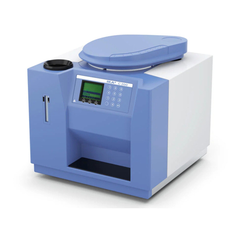
IKA RV 10 control User manual

IKA RV 10 control
IKA RV 10 auto
Operating instructions EN 4
使用说明 ZH 29
사용 설명서 KO 54
JA 79
คำ�แนะนำ�กำ�รใช้งำ�น TH 104
Petunjuk pengoperasian
ID 129

2
B
E
A
C
D
ZH
A RV 10 auto 主机
B 加热锅
C 真空缓冲回流瓶支架
D 真空缓冲回流瓶
E 玻璃组件
EN
A RV 10 auto drive
B Heating bath
C Bracket
D Woulff bottle
E Glassware
JA
A RV 10 auto
B
C
D
E
TH
A ชุดขับRV 10 auto
B อ่างทำาความร้อน
C แบร็คเก็ต
D ขวดควบแน่น
E เครื่องแก้ว
KO
A 드라이브 RV 10 auto
B 가열 배스
C 브래킷
D 응축물 플라스크
E 유리 제품
ID
A Drive RV 10 auto
B Bak pemanas
C Bracket
D Bejana kondensasi
E Perkakas dari kaca

3
EN
A"Power" switch
B"Power" key
CLift position "
" key
DLift position "
" key
E“Rotating speed” key
F"Vent" key
G"Vacuum" key
H"Menu" key
J"Back" key
KStart/Stop knob
EHJ
F
K
G
D
C
B
A
ZH
A电源开关
B"电源"按键
C上升按键 "
"
D下降按键 "
"
E"转速"按键
F"通风"按键
G"真空"按键
H"菜单"按键
J"返回"按键
K启动/停止按钮
KO
A"전원" 스위치
B"전원" 키
C리프트 위치 "
" 키
D리프트 위치 "
" 키
E“회전 속도” 키
F"환기" 키
G"진공" 키
H"메뉴" 키
J"뒤로" 키
K시작/중지 손잡이
JA
A
B
C
D
E
F
G
H
J
K/
TH
Aสวิทช์"เป
ิด-ป
ิด"
Bปุ
่ม "เป
ิด-ป
ิด"
Cปุ
่ม"
" สำาหรับตำาแหน่งของอุปกรณ์ยก
Dปุ
่ม"
" สำาหรับตำาแหน่งของอุปกรณ์ยก
Eปุ
่ม "ความเร็วการหมุน"
Fปุ
่ม "ระบาย"
Gปุ
่ม "สุญญากาศ"
Hปุ
่ม "เมนู"
Jปุ
่ม "ย้อนกลับ"
Kปุ
่มเริ่ม/หยุด
ID
ASakelar “Daya”
BTombol “Daya”
CTombol ”
” posisi lift
DTombol “
” posisi lift
ETombol “Kecepatan rotasi”
FTombol “Ventilasi”
GTombol “Vacuum”
HTombol “Menu”
JTombol “Kembali”
KKenop Mulai/Henti

4
Source language: German EN
Contents
Explication of warning symbols
EU Declaration of conformity
Page
Device setup 2
EU Declaration of conformity 4
Explication of warning symbols 4
Safety instructions 5
Intended use 6
Unpacking 7
Useful information 7
Vacuum control 8
Setting up 9
Commissioning 15
We declare under our sole responsibility that this product corresponds to the directives 2014/35/EU, 2006/42/EC, 2014/30/EU and
2011/65/EU and conforms with the following standards or normative documents: EN 61010-1, EN 61010-2-051, EN 61326-1, EN
60529 and EN ISO 12100.
Interfaces and outputs 24
Maintenance and cleaning 25
Accessories 25
Error messages 26
Warranty 27
Technical data 28
Drawings for mounting the glassware 154
Drawings for connecting the hose system 156
Solvent table (excerpt) 159
DANGER
DANGER
CAUTION
WARNING
NOTICE
Indicates an imminently hazardous situation, which, if not avoided, will result in death, serious injury.
Indicates a potentially hazardous situation, which, if not avoided, can result in death, serious injury.
Indicates a potentially hazardous situation, which, if not avoided, can result in injury.
Indicates practices which, if not avoided, can result in equipment damage.
Danger - Reference to exposure to a hot surface!

5
Safety instructions
For your protection
• Read the operating instructions completely before starting up
and follow the safety instructions.
• Keep the operating instructions in a place where they can be
accessed by everyone.
• Ensure that only trained staff work with the appliance.
• Follow the safety instructions, guidelines, occupational health
and safety and accident prevention regulations. When working
under a vacuum in particular!
• Wear your personal protective equipment in accordance with
the hazard category of the medium to be processed. There may
be a risk of:
- splashing liquids,
- body parts, hair, clothing and jewellery getting caught,
- injury as a result of glass breakage.
Inhalation of or contact with media
such as poisonous liquids, gases,
spray mist, vapors, dusts or biological
and microbiological materials can be
hazardous to user.
• Set up the device in a spacious area on an even, stable, clean,
non-slip, dry and fireproof surface.
• Ensure that there is sucient space above the device as the
glass assembly may exceed the height of the device.
• Prior to each use, always check the device, accessories and
especially the glass parts for damage. Do not use damaged
components.
• Ensure that the glass assembly is tension-free! Danger of
cracking as a result of:
- stress due to incorrect assembly,
- external mechanical hazards,
- local temperature peaks.
• Ensure that the stand does not start to move due to vibrations
respectively unbalance.
• Beware of hazards due to:
- flammable materials,
- combustible media with a low boiling temperature.
Only process and heat media that has a
flash point higher than the adjusted safe
temperature limit of the heating bath
that has been set. The safe temperature
limit of the heating bath must always
be set to at least 25 °C lower than the
fire point of the media used. (acc. to EN
61010-2-010)
• Do not operate the appliance in explosive atmospheres, with
hazardous substances or under water.
• Only process media that will not react dangerously to the
extra energy produced through processing. This also applies to
any extra energy produced in other ways, e.g. through light
irradiation.
• Tasks with the device must only be performed when operation
is monitored.
• Operation with excess pressure is not permitted (for cooling
water pressure see “Technical Data“).
• Do not cover the ventilation slots of the device in order to
ensure adequate cooling of the drive.
• There may be electrostatic discharges between the medium and
the drive which could pose a direct danger.
• The appliance is not suitable for manual operation (except lift
movement).
• Safe operation is only guaranteed with the accessories described
in the “Accessories” chapter.
• Refer to the operating instructions for the accessories, e.g.
vacuum pump, heating bath.
• Position the positive pressure outlet of the vacuum pump under
a fume hood.
• Only use the device under an all side-closed exhaust, or a
comparable protective device.
• Adapt the quantity and the type of distill and to the size of
the distillation equipment. The condenser must work properly.
Monitor the cooling water flow rate at the condenser outlet.
• The glass equipment must always be ventilated when working
under normal pressure (e.g. open outlet at condenser) in order
to prevent a pressure build-up.
• Please note that dangerous concentrations of gases, vapors
or particulate matter can escape through the outlet at the
condenser. Take appropriate action to avoid this risk, for
example, downstream cold traps, gas wash bottles or an
effective extraction system.
• Evacuated glass vessels must not be heated only on one side;
the evaporating flask must rotate during the heating phase.
• The glassware is designed for operation under a vacuum of up
to 1 mbar. The equipment must be evacuated prior to heating
(see chapter ”Commissioning”). The equipment must only be
aired again after cooling. When carrying out vacuum distillation,
uncondensed vapors must be condensed out or safely dissipated.
If there is a risk that the distillation residue could disintegrate in
the presence of oxygen, only inert gas must be admitted for
stress relief.
Avoid peroxide formation. Organic
peroxides can accumulate in distillation
and exhaust residues and explode
while decomposing! Keep liquids that
tend to form organic peroxides away
from light, in particular from UV rays
and check them prior to distillation and
exhaust for the presence of peroxides.
Any existing peroxides must be
eliminated. Many organic compounds
are prone to the formation of peroxides,
e.g. dekalin, diethyl ether, dioxane,
tetrahydrofuran, as well as unsaturated
hydrocarbons, such as tetralin, diene,
cumene and aldehydes, ketones and
solutions of these substances.
The heating bath, tempering medium,
evaporation flask and glass assembly
can become hot during operation and
remain so for a long time afterwards!
Let the components cool off before
continuing work with the device.
Avoid delayed boiling! Never heat
the evaporating flask in the heating
bath without switching on the rotary
drive! Sudden foaming or exhaust
gases indicate that the flask content
is beginning to decompose. Switch
off heating immediately. Use the lifting
mechanism to lift the evaporation flask
out of the heating bath. Evacuate the
danger zone and warn those in the
surrounding area!
DANGER
CAUTION
CAUTION
WARNING
DANGER
6
Intended use
• Use
Together with the accessories recommended by IKA, the device
is suitable for:
- quick and gentle distillation of liquids,
- evaporation of solutions and suspensions,
- crystallization, synthesis or cleaning of fine chemicals,
- drying of powder and granulate material,
- recycling of solvents.
Mode of operation: Tabletop device
• Area of use
Indoor environments similar to that a laboratory of research,
teaching, trade or industry area.
The safety of the user cannot be guaranteed:
- If the device is operated with accessories that are not supplied
or recommended by the manufacturer;
- If the device is operated improperly or contrary to the manu-
facturer’s specifications;
- If the device or the printed circuit board are modified by the
third parties.
• Further remarks
Legal bases and country-specific characteristics, especially for
medicine and food:
The operator is responsible for compliance with the laws and
regulations applicable to him.
Safety lift
When the device is switched off or the power supply disconnected,
the internal safety lift removes the evaporating flask from the
heating bath.
The safety lift at loss of power is designed for a maximum total
weight (glassware and solvent) of 3.1 kg.
Sample calculation of the maximum load with vertical glassware
and a 1 litre flask:
Condenser + receiving flask + evaporating flask + fittings=
1200 gr + 400 gr + 280 gr + 100 gr = 1980 gr
Maximum loading of solvent = 3100 gr – 1980 gr = 1120 gr
Due to the design, operation of the safety lift cannot be
guaranteed for higher loads!
When using other types of condensers such as dry ice or intensive
condensers, and also when using return distillation distributors
with slip-on condensers, it may be necessary to reduce the load by
the amount of the added weight of the glass apparatus.
Thus, prior to distillation, check whether the lift goes up without
power when laden with the glassware and distillation material.
The safety lift must be checked daily prior to operation. Use
the motor to move the lift to the lowest position and press the
"Power" key on the front plate or the main switch on the back
right side of the device using the maximum total weight of 3.1 kg.
The evaporating flask is lifted out of the heating bath.
When using for the first time or after a long period of inactivity,
proceed as follows: use the motor to move the lift several times
to the top and bottom positions by pressing the lift function keys
prior to interrupting the power supply.
If the safety lift does not work, please contact the IKA Service
department.
For the evaporating equipment (evaporating flask plus contents),
the maximum permissible weight is 3.0 kg! Loads greater than this
risk breakage of glass at the vapor tube!
Ensure that the safety lift has been powered down.
When working with large loads, always use low speeds.
Unbalanced loads can result in breakage of the vapor tube!
• A vacuum may be formed inside the glassware in the case of
power outage. The glassware must be vented manually.
Never operate the device when the
evaporation flask is rotating and the lift
is raised. Always lower the evaporation
flask into the heating bath first before
starting the rotation drive. Otherwise
hot tempering medium may be sprayed
out!
• Set the speed of the drive so no tempering medium is sprayed
out as a result of the evaporation flask rotating in the heating
bath. If necessary reduce the speed.
• Do not touch rotating parts during operation.
• Imbalance may result in uncontrolled resonance behavior of
the device or assembly. Glass apparatus may be damaged or
destroyed. In the event of unbalance or unusual noises, switch
off the appliance immediately or reduce the speed.
• The appliance does not start up again automatically following a
cut in the power supply.
• The device can only be disconnected from the mains supply by
pulling out the mains plug or the connector plug.
• The socket for the mains cord must be easily accessible.
• Always check evaporation processes before starting automatic
operation. Automatic operation must not be used for unfamiliar
evaporation processes. The following automatic modes are
available in addition to manual mode:
- 100% distillation,
- Volume-/quantity-dependent distillation.
For protection of the equipment
• The voltage stated on the type plate must correspond to the
mains voltage.
• Socket must be earthed (protective ground contact).
• Removable parts must be refitted to the appliance to prevent
the infiltration of foreign objects, liquids, etc.
• Protect the appliance and accessories from bumps and impacts.
• The appliance may only be opened by experts.
CAUTION

7
Useful information
In order to prevent this, the condenser loading safety monitoring
system can be activated. Before activating the safety monitoring,
first carry out several distillations, noting the value given under
menu option “EVAPORATOR Advanced Max power of coo-
ler”. Now calculate the heat rejection rate using the following
formula:
Cooler power limit = Max power of cooler * 1.3
Enter this value under menu option “EVAPORATOR Advanced
Cooler power limit”. The device will now stop the measure-
ment and issue an error message if the threshold for the conden-
ser is exceeded. If the configuration of the condenser equipment
or the distillation process is modified, then it may be necessary to
re-evaluate the maximum condenser loading.
The device is equipped with a piston-operated safety mechanism.
The glass apparatus may contain a vacuum following interruption
to the power supply; vent the system before switching back on.
If the power cuts out, the evaporation flask is automatically lifted
out of the heating bath by an integrated gas spring.
The safety lift must be checked daily
prior to operation. For more informati-
on see the section "Safety Instructions
– Safety Lift"!
Distillation is a thermal separating process for liquid compounds
based on substance-specific, pressure-dependent boiling points
through evaporation and subsequent condensation.
The boiling point temperature decreases with decreasing external
pressure which means that work is usually done under reduced
pressure. In this way the heating bath can be maintained at a
constant temperature (e.g. 60 °C). Using the vacuum, the boi-
ling point is set with a steam temperature of approx. 40 °C. The
cooling water for the condensation cooler should not be warmer
than 20 °C (60-40-20 rule).
A chemical resistant membrane pump with a vacuum controller
should be used to create the vacuum. The pump is protected from
solvent residue by the addition of a condensate flask and/or a
vacuum separator. Working with a jet pump to create a vacuum
can only be recommended to a limited extent as the solvents may
contaminate the environment when using these systems.
Speed, temperature, piston size and system pressure all affect the
evaporator air capacity.
The optimum capacity of the flow-through condenser is approx.
60%.
This corresponds to condensation on approx. 2/3 of the cooling
coil.
With larger capacities there is the risk that the uncondensed sol-
vent vapor will be extracted.
CAUTION
• Unpacking
- Unpack the device carefully.
- Any damage should be notified immediately to the shipping agent (post, rail or logistics company).
• Scope of delivery
Unpacking
Drive RV 10 auto
Heating bath HB digital
Vertical glassware RV 10.1
Vertical glassware RV 10.10 coated
Condensate flask
Bracket
Cooler locking device, compl.
Vacuum hose (2 x 0.55 m)
Water discharge hose (1 x 1 m)
Vapour tube
Ring spanner
Handhold
RV 10.4002 vacuum valve for laboratory vacuum system
IKA Vacstar digital vacuum pump
Operating instructions
RV 10 control V xxx xxxxxxxxx x
RV 10 control V-C xx xxxxxxxxxx x
RV 10 control FLEX xx xxxxxxxxx x
RV 10 auto V xxx xxxxxxxx x
RV 10 auto V-C xx xxxxxxxxx x
RV 10 auto FLEX xx xxxxxxxx x
RV 10 auto pro V xxx xxxxxxxx x x
RV 10 auto pro V-C xx xxxxxxxxx x x
RV 10 auto pro FLEX
xx xxxxxxxx x x

8
In addition to offering a full range of manual and semi-automatic
evaporation operating modes, the RV 10 control rotary evapora-
tor can also be used for fully automatic and quantity-controlled
evaporation processes. Standard fittings for fully-automatic ope-
ration include a vacuum controller, a cooling water differential
temperature measurement sensor and a cooling water flow rate
meter. The vacuum can be controlled in both two-position and
speed-controlled pumping operation with the help of the integra-
ted vacuum controller. The device is designed for operation with a
cooling water supply system (e.g. laboratory thermostat), but can
also be run off a water supply line. Please refer to the Technical
Data for information on cooling water pressure, temperature con-
stancy, flow rate and local regulations.
We recommend using the RV 10.5001 water regulator valve
when operating directly off a water supply line.
This valve allows the cooling water flow rate to be adjusted and
automatically cuts off the cooling water supply on completion of
the distillation process.
The RV 10.5002 water filter can be used to prevent particles of
dirt passing from the water supply line into the valve mechanism.
If pressure reduction is required, we recommend fitting the
RV 10.5003 pressure regulator valve in the pipe immediately
downstream of the pick-off point.
Automatic volume-dependent distillation: The apparatus
must be brought up to operating temperature. This is achieved by
conducting a test distillation.
RV 10 auto: The rotary evaporator is fitted as standard with
speed control pump, internal venting vale and a pressure measu-
ring chamber.
RV 10 control (for vacuum): The external two-position vacuum
control is also available for the application which in-house vacuum
system is available. Vacuum valve RV 10.4002 must be used.
RV 10 control
A vacuum is made in the glassware with the help of a vacuum
pump. The vacuum pump operates at constant speed which ge-
nerally cannot be adjusted.
Once the target value is reached the suction line is interrupted.
The device will fall slightly short of the target value setting due
to the minimum time difference from detection of the pressure
value, the target value comparison for switching the vacuum valve
and the suction line of the vacuum generating system. If the pres-
sure in the system increases again due to the natural leakage rate,
the valve opens the suction line.
The switching frequency and accuracy can be set via the hysteresis
setting.
With the VC 2.4 pump control connected, the power supply to
the pump is also switched on and off accordingly. This reduces the
noise level and increases the service life of the pump membranes
and motor.
The actual value fluctuates in size of the set hysteresis around the
target value.
Automatic boiling point recognition is not accurately possible
when using two-position control.
Schematic view of a two-position vacuum control
Vacuum control
RV 10 auto
Imprecision of the two-position control is avoided by using the
speed-vacuum control.
However a vacuum pump with a controlled speed is needed for
speed-vacuum control; the RV 10.4002 vacuum valve is not requi-
red and must not be connected! To do so, connect the vacuum
pump (e.g. IKA Vacstar digital pump) to the port on the rear of
the rotary evaporator.
With this kind of control, the speed of the pump, and therefore
its suction power, is reduced the closer the measured pressure
reaches the target value.
Once the target value is reached, the pump only operates accor-
ding to the leakage rate.
It is possible to achieve quieter operation and more exact vacuum
control.
The speed-vacuum control on the RV 10 is controlled automati-
cally as soon as an appropriate vacuum pump is attached.
Automatic boiling point recognition is possible with this type of
control, i.e. the system reaches and keeps the solvent at its boiling
point in automatic mode.
As it is not necessary to know the boiling point of the solvent
when in automatic boiling point recognition mode (unlike in the
case of volume-dependent distillation), these two operating mo-
des are mutually exclusive.
Schematic view of speed-vacuum control

9
Setting up
Set the drive at an angle of approx. 30°
• Remove the clamping device for the angle setting of the rota-
tion drive on the right side of the lift by rotating the knurled
screw counterclockwise (gently press and rotate the knurled
screw (1) at the same time to move it further in or out).
• Set the drive at an angle of approx. 30°.
Loosen transportation lock!
CAUTION
Drive RV 10 auto
• Hold the lift with your hand on the height position and remove
the thumb screw (1) by turning counterclockwise on the back
of the appliance.
•
Once the transportation lock has been removed, the lift moves
slowly to its upper end position. The distance is approx. 140 mm.
• Connect the supplied power cable to the connection socket (2).
Adjustable base
Note: Only one base foot is adjustable.
Fix the bracket
Insert the bottle and attach the supplied hose connectors to the
bottle
• Then secure the rotation drive from being accidentally turned
by tightening the knurled screw in a clockwise direction.
1
2 1

10
Glassware
Fit the condenser seal
• Place the condenser seal in the condenser receptacle and fit the
glassware to the device according to the assembly instructions.
NOTE: Please read the operating instructions of the glassware for
the safe handling of laboratory glassware !
• There is a locking knob for locking or unlocking the locking
device.
If a red mark is shown, the locking device is unlocked, otherwise
it is locked.
To lock or unlock the locking device, push the locking knob to
the end position.
•
Open the locking device on the drive head by turning it 60°
counterclockwise. Then you can see a red mark .
•
Feed the vapour tube in until it stops.
•
Then, lock the locking device by turning it clockwise by 60°.
• Pushing the lock knob to the end position, the red mark should
be covered and invisible.
• The vapour tube is not allowed to be pulled out!
• Check the correct axial locking device on the vapour tube.
• Keep the red mark invisible.
CLICK
Heating bath
Refer to the chapter “Operation“ in the
heating bath instruction manual!
• Place the heating bath on the stand of the rotation drive and
push it into the left position.
Note: Data is exchanged between the drive unit and the heating
bath by means of an infrared link (1). Please note that reliable
communication is only guaranteed when the infrared beam has
clear line-of-sight to the detector.
CAUTION
1

11
Assembling the vertical glassware cooler locking device
• Assemble the condenser locking device according to the dia-
gram.
• Mount the plate (1) using the thumb screw (2).
• Put the support rod (4) on the plate (1) and attach it with the
screw nut (3).
• Attach the rubber protector (5).
• Fasten the Velcro®band (6) to the support rod (4).
• Secure the vertical glassware with the Velcro®band (6).
No stand is required if the condenser has been properly fitted
and secured by tightening the condenser union nut on the rotary
drive.
The purpose of the stand is solely to prevent the condenser from
twisting.
If the stand is fitted incorrectly, the
strong forces at the Velcro strap can
cause stresses within the glass, which
in turn can cause damage to the glass
condenser.
After the condenser has been fitted, the stand is attached to the
rotary drive. Make sure that the condenser is installed parallelly to
the lift body.
CAUTION
1
2
5 6
4
3
First use
• Insert vapor tube (1).
• Insert the vacuum seal (2). Pay attention to the correct positon
of the vacuum seal!
• Slide the union nut (3b) over the flange on the condenser (3a).
• Also slide the annular spring (3c) over the flange on the con-
denser (3a).
• Position the condenser (3a) on top of the seal (2).
• Tighten the union nut (3b) by hand onto the threaded flange.
Run the device for 20 minutes at 120 rpm. Finally, retighten the
union nut (3b) by hand.
Note: Follow the mounting instructions for the glassware.
1
2
3a
3b
3c

12
Item Designation Quantity
RV 10.1
non-coated
RV 10.10
coated
RV 10.2
non-coated
RV 10.20
coated
RV 10.3
non-coated
RV 10.30
coated
RV 10.4
non-coated
RV 10.40
coated
RV 10.5
non-coated
RV 10.50
coated
RV 10.6
non-coated
RV 10.60
coated
1Receiving flask 1 1 1 1 1 1
2Clamp (stainless steel) 1 1 1 1 1 1
4Stopcock 1 1 1 1 1 1
5Pipe tube 1 - 1 1 1 1
6Condenser 1
Vertical condenser
1
Diagonal condenser
1 Vertical-intensive
condenser
1 Dry ice condenser 1 Vertical condenser 1 Vertical-intensive
condenser
7Connection 1
Vacuum connection
1
Introduction sleeve
1
Vacuum connection
- 1
Vacuum connection
1
Vacuum connection
8Clamp (plastic) 1 1 1 - 1 1
10 Evaporation flask 1000 ml 1 1 1 1 1 1
11 Ball joint clamp RV 05.10 1 1 1 1 1 1
12 Screw joint cap 4 4 4 2 4 4
13 Hose connection 4 4 4 2 4 4
14 Manifold - - 1 - 1 1
15 Cover cap - - - 1 - -
16 Cartridge - - - 1 - -
17 Ring, slotted - - - 1 - -
18 Washer 1 - 1 1 1 1
19 O-ring - - - 1 - -
20 Plug, high vacuum - - - - 1 1
Note:
The PTFE tube (5) with the washer (18) can be mounted optionally on the vertical glass sets.
It serves for filling the evaporator flask when there is a vacuum in the glass set.
Solvent can be sucked through the PTFE tube into the evaporator flask by opening the stopcock (4).
Mounting the glassware
Note: Observe "Drawings for mounting the glassware" on page 154.
Mounting the washer
Drainage washer
Note: Pay attention to the correct position of the washer.
Removing the condenser
• Use the ring spanner provided to loosen union nuts that are
tightly fitted.
• Loosen the union nut by turning counterclockwise.
• Remove the Velcro®.
Note: Ring spanner is only used for removing the condenser,
while fixing the condenser please use hands.

13
Hose system
RV 10.3_30
RV 10.2_20
RV 10.1_10
RV 10.4_40
RV 10.5_50
RV 10.6_60
Hose clamp
for silicone hose
pos. 5, 6 & 7
for vacuum hose
pos. 8
Hose clamp RV 10.5001 Water valve
(Optional)
RV 10.4002 Vacuum valve
Silicon hose (inner dia. 6 mm)
Silicon hose (inner dia. 7 mm)
Vacuum hose
1
10
10 10 10 10 10
6 7 89
234
for water
Silicon hose (inner dia. 5 mm)
5
for water Connector
for water valve
for water
Note: Observe "Drawings for connecting the hose system" on page 156.
RV 10 control operation
• Fit RV 10.4002 vacuum, in the bracket provided for this purpose
and connect the vacuum hose to the valve.
Connect RV 10.4002
RV 10 auto operation
• No additional valve is required for vacuum normal operation
with a speed-vacuum control pump. Connect the pump's vacu-
um inlet directly to the RV 10 pump hose connection.
•
Connect the pump controller cable to RV 10 control.
Connect RV 10 temperature sensor (dT)
• Connect the temperature sensor to the lower socket (dT). Al-
ways check for correct direction of the arrow.
Note: When connecting the
pump controller cable, make
sure that the snap-and-lock
plug has been inserted into the
stop position inside the pump
controller cable connection
.
Note: When connecting the
temperature sensor, make sure
that the snap-and-lock plug has
been inserted into the stop posi-
tion inside the temperature sen-
sor connection
.

14
Water
• Connect the water inlet to the water supply (with op-
tional RV 10.5001 water regulator valve). Please re-
fer to the technical data relating to the water supply.
The RV 10.5001 water regulator valve is not suitable for use on
the condenser unit because it would reduce the flow rate too
greatly.
• Connect the water hoses to the glass condenser (short hose
(1) = lower outlet, long hose (2) = upper inlet) and fix hoses in
place.
1
2
•
Connect the water outlet hose (supplied) by pushing it onto the
nipple until the stop inside the connection socket is reached.
Note: Ensure that the condenser inlet and condenser outlet are
connected correctly.
Automatic distillation cannot be carried out if the water inlet and
outlet hoses are not fitted according to the instructions and illus-
trations, since this would cause the temperature readings for the
inlet and outlet to be measured incorrectly.
•
Release the hose connection using the supplied tool.
Condenser inlet
Condenser outlet
•
Insert the valve connector cable (RV 10.5001, RV 10.4002) into
the appropriate socket. Connect the speed-vacuum control
pump. As a result, the RV 10 control automatically switches to
normal speed-vacuum control operation.
•
Connect "LOAD" to the Condensate flask and the Condensate
flask to the vacuum connector on the condenser using the vacu-
um hoses supplied. Please note that the vacuum must always be
connected at the highest connection point on the condenser.
Water out
Water in

15
Working screen at the time of delivery
The start screen appears for a few se-
conds after the device is switched on. The
device name and the software versions
are displayed.
An information prompt then appears to
download the IKA firmware update tool.
Explanation of symbols on the working screen
Commissioning
Symbol Designation Description
Bluetooth®This symbol means the RV 10 is communicating via Bluetooth® with a PC or tablet. The symbol no
longer appears if no Bluetooth®communication is being performed.
USB This symbol means RV 10 is communicating via a USB cable. The symbol no longer appears if no
USB cable is being used for communicating with the station.
Limit This symbol indicates if a minimum or maximum limit of a set value is reached.
Temperature sensor This symbol appears when the temperature display is active in the display.
PC control This symbol means that device is connected to a computer and that it is being controlled by the
computer.
Program controlled This symbol means that device is being controlled by a program.
Rotation This symbol indicates that the rotation is in continuous mode and indicates the direction of rota-
tion.
Drying This symbol indicates that the drying option was selected (only in 100 % mode).
Flow rate This symbol indicates that a fluid (water) is running through the system.
Cooler connected This symbol indicates that a cooler is connected and running.
Venting This symbol indicates that the venting valve is open. If this symbol is not shown the venting valve
is closed.
Vacuum This symbol indicates that the pressure inside the RV 10 system is lower than the atmosphere
pressure.
Detecting This symbol is shown during the automatic evacuation mode.
Boiling This symbol indicates that a boiling point was found (only in automatic mode).
After this, the working screen appears automatically on the dis-
play.
The symbols displayed change depending on the status and set-
tings of RV 10 auto.

16
Factory settings
Menu structure
Evaporator Modes Automatic
Manual...................................................................................................... 1013 mbar
Pump %...................................................................................................... 50%
Volume
Program..................................................................................................... -
100%
Bath medium.............................................................. Water
Solvent....................................................................... Acetic acid
Start temperature........................................................ 60 °C
Target......................................................................... 100 ml
Eciency.....................................................................
80%
Adjustment..................................................................
-
Cleaning
Actions after distillation
Limits
Hysteresis
Solvent library
Menu
Solvent...................................................................... Acetic acid
mm:ss.......................................................................
30:00
Minimum..................................................................... 2 mbar
mm:ss.......................................................................
06:00
Minimum.....................................................................
0%
Drying........................................................................ -
Maximum..................................................................... 1013 mbar
Maximum.................................................................... 100%
Name....................................................................
-
Bath temperature................................................... -
Eciency................................................................
-
Enthalpy.................................................................
-
i-factor...................................................................
-
Formula................................................................. -
Rotation speed......................................................
-
Heat capacity......................................................... -
Density...................................................................
-
Boiling point.......................................................... -
Name.................................................................... -
Bath temperature..................................................
-
Eciency............................................................... -
Enthalpy................................................................ -
i-factor.................................................................. -
Formula.................................................................
-
Rotation speed...................................................... -
Heat capacity.........................................................
-
Density.................................................................. -
Boiling point..........................................................
-
Start after...
Stop heating........................................................................ -
Manual
Automatic.............................................................................................
Manual Value.............................................................................
±15 mbar
Add solvent
Add solvent
Add solvent
Add solvent
Add solvent
Acetic acid
Acetone
Acetonitrile
...
Xylene
Duration
Stop rotation.......................................................................
Close water valve.................................................................
Pump %
Pump speed
Clean now.................................................................................................. -
Lift up..................................................................................
Open venting valve..............................................................
Cleaning.............................................................................
-
Calculator Name.......................................................................................................... Acetic acid
Heating bath temperature............................................................................ 60 °C
Vapor temperature ..................................................................................... 40 °C
Pressure...................................................................................................... 46 mbar
Value........................................................................ 20%

17
Timer Time
Timer function
Display......................................................................................................................................
-
Beep after timeout........................................................................ -
Activate........................................................................................ -
hh:mm:ss........................................................... 00:00:00
Display Timer......................................................................................................................................
Δ T..........................................................................................................................................
Flow rate................................................................................................................................
Cooler power...........................................................................................................................
Programs Program 1-10
Last Measurement
Select................................................................................................
-
Save as........................................................................................
-
Edit
Edit
Pressure.....................................
-
Pressure............................................
-
Delete...............................................................................................
-
Delete.......................................................................................... -
Edit
Edit
Insert..............................................................
-
Insert................................................................
-
Rotation (Speed)........................
-
Rotation (Speed)...............................
-
Delete.............................................................
-
Delete.............................................................. -
hh:mm:ss...................................
-
hh:mm:ss..........................................
-
Rotation
Speed limit
Interval mode
Minimum........................................................................................ 5 rpm
CcwInterval
Maximum.......................................................................................
300 rpm
Cw
Activate........................................................................................... -
Value............................................ 00:10
Value......................................
00:10
Advanced Flow control.............................................................................................
Cooler power limit.................................................................................... 900 w
Bath medium........................................................................................... Water
Max power of cooler................................................................................ 0 w
Factory settings
Safety Password
Continue after power failure Activate..................................................................... -
Time mm:ss............................................... 00:10
Value...................................................................................................... 0

18
Service Valves
Temperature adjustment..............................................................................................
-
Pump........................................................................................................................... -
Venting valve............................................................ -
Water valve..............................................................
-
Vacuum valve...........................................................
-
Settings Language English...............................................................................
Deutsch............................................................................
-
Français............................................................................
-
Español............................................................................. -
Italiano.............................................................................
-
中文................................................................................ -
한국어............................................................................
-
............................................................................ -
Português.........................................................................
-
Pусский язык.................................................................... -
Units
Display
Communication
Sound
Factory settings
Information
mbar.......................................
mL..........................................
Black.......................................
Value..............................................
100%
Value................................................... 100%
mmHg...................................... -
Firmware update info........................................................ -
Pump % max....................................................................
100%
Rot. speed min................................................................. 5 rpm
Operating hours................................................................
0 hours
hPa.......................................... -
g.............................................. -
White....................................... -
Torr.......................................... -
Logic version.................................................................... -
Display version.................................................................. -
Pressure max..................................................................... 1100 mbar
Pressure min...................................................................... 1 mbar
Pump % min.....................................................................
0%
Rot. speed max.................................................................
300 rpm
Pressure
Background
Menu values...................................................................... -
Device name..................................................................... RV 10 auto
Volume
Brightness
Programs...........................................................................
-
Bluetooth..........................................................................
Labworldsoft 5 protocol....................................................
Key Tone............................................................................ -
Firmware update info........................................................ -
Solvent library.....................................................................
-
All......................................................................................
-
Amount
Change the menu items, values or settings by turning the rotary knob and confirm by pushing it.
Factory settings

19
Automatic: In this mode, the system will detect the actual eva-
poration by checking the temperature difference between water
input and water output. The default setting of the medium tem-
perature is 60 °C, the user can set the medium temperature ma-
nually. If the expected evaporation temperature is higher than 90
°C, please change the medium from water to oil, and use high
temperature medium, e.g. silicone oil. In this mode, measurement
will start automatically when the heating bath reaches the set
temperature, the temperature difference will be below a threshold
value, the water flow rate must be within 30-100 L/h, and the lift
moves down automatically. You can change the speed manually.
Manual: In this mode the user can set all values manually. When
the measurement is started the system is evacuated until it reaches
the set pressure value. The lift has to be moved manually.
Pump %: In this mode the pump can be run in a long term, set-
ting a value between 100 % and 1% of the possible pump speed.
Volume: This mode is used to distill a specific amount of the used
solvent. The measured values of the cooling water flow rate and
the cooling water temperature difference from the basis for a heat
balance calculation used to determine the quantity of distillate at
every stage of the distillation. The distillation process is stopped
when the specified quantity of distillate has been reached.
Solvent: Select the solvent you want to distill.
Target: Enter the amount, which you want to distill off.
Eciency: Balancing requires a precise thermal eciency to be
entered.
Adjustment: The eciency is dependent on a combination of fac-
tors that affect the distillation process, so it is initially estimated.
The first time a distillation process is carried out should therefore
be used for adjustment. The actual eciency will be recalculated
after the measurement based on the target volume and the actu-
ally distilled volume.
Program: This entry is a link to the “Programs” menu.
100 %:
Solvent: The distillation process is stopped when the measured
cooling water temperature difference falls below a threshold va-
lue, i.e. as soon as a solvent has been completely distilled off.
Drying: The cooling water temperature difference is not moni-
tored if this option is activated, e.g. use in processes for drying
powdered media.
Cleaning
Start after...: Set the minimum time that a measurement has to
run before the cleaning after the measurement is activated. The
cleaning process starts when the measurement has been running
for at least the set time.
Duration: Set the duration of the cleaning process.
Pump speed: The set pump speed in the cleaning menu is used to
set the speed of the pump during the cleaning process.
Higher speed causes partial vacuum in
the glassware if the system is closed.
High speed cleaning affects the pump
membrane lifetime.
Clean now: This starts the cleaning process manually.
Limits
Manual: This option allows user to set the permitting operating
vacuum range.
Pump %: This option allows user to set the permitting operating
pump speed range.
Hysteresis
The (vacuum) hysteresis value describes
the difference between the closing and
opening pressures for the vacuum valve.
Setting the hysteresis value too low can
have a negative effect on the vacuum
pump and the vacuum valve. The hyste-
resis function is only used for indoor vacuum or uncontrollable
vacuum pumps.
Automatic: Hysteresis is always 10 % of the actual pressure.
Manual: Manual value specification of hysteresis.
Solvent Library
User can select the solvent which will be
distilled, the parameters (such as, Name,
Formula, Bath temperature, Rotation
speed, Boiling point, Eciency, Heat ca-
pacity, Enthalpy, Density and i-factor) will
be shown in the library. User can set the
evaporating bath temperature, eciency and the rotation speed.
It is possible to add up to five new customized solvents to the
solvent list. The customized solvents appear in orange and can be
found on the top of the solvent library.
Name and formula: The name and the formula help to identify
the solvent.
NOTICE
Menu (details)
1. Evaporator
Modes

20
2. Rotation
3. Timer
Timer function
Time: This setting allows the user to specify the actual time for
the measurement procedure in the manual mode. A default time
can also be set for the timer, which allows the user to start the
measurement task for a standard time. The device stops automa-
tically after expiry of the set time, and the set time used for the
measurement procedure appears on the display.
Interval mode
The rotation can be run in an interval mode of alternating the
rotation direction.
Interval: The interval sets the time how long the rotation takes
place in one direction.
Activate: This entry activates the interval mode for the rotation.
Speed limit
The “Speed limit” menu allows the user to set the desired maxi-
mum and minimum speed limit for the rotation.
Note: The user can stop the measurement procedure before ex-
piry of the set time. In this case the countdown of the timer is
interrupted.
Beep after timeout: This menu item allows the user to turn on/
off the sound that occurs when the timer reaches 00:00:00. A tick
shows that the option is activated.
Activate: In this menu the user can activate or deactivate the
timer function. A tick shows that the option is activated.
Display
In the “Timer” menu the user can specify that the timer is dis-
played on the display/working screen. A tick shows that the opti-
on is activated.
Calculator
It helps you to calculate the boiling point (vapor temperature) of
solvent, heating bath temperature and pressure. If one of the 3
values has been defined, the other 2 values will be given.
Actions after distillation
It is possible to define actions when the measurement is stopped
(manually or automatically).
Advanced
Flow control: This setting can be deactivated in the manual mode
if dry ice is used instead of a cooler.
Bath medium: Select either water or oil as the medium for the
heating bath. If water is the medium, please select water, the tem-
perature will be from 20 °C to 90 °C. If oil is the medium, please
select oil, the temperature range will be from 20 °C to 180 °C.
Cooler power limit: This setting is used to limit the cooler power.
If the actual cooler power is higher than the cooler power limit a
warning appears and the measurement is stopped.
Max power of cooler: This value shows the maximum cooler
power value of a measurement. This value serves as information
and cannot be changed.
4. Display
In this menu the user can set which values (Timer, Flow rate, ΔT
and/or Cooler power) should be shown on the main screen. A tick
shows that the option is activated.
Other manuals for RV 10 control
4
This manual suits for next models
10
Table of contents
Languages:
Other IKA Laboratory Equipment manuals
Popular Laboratory Equipment manuals by other brands

REITEL
REITEL SUPERSTEAM operating instructions

Droplet
Droplet UHSAS Operator's manual

Helmer Scientific
Helmer Scientific i.C3 iLR105-GX user guide

W&H Med
W&H Med Lisa VA131-17 Instructions for use

Dionex
Dionex ICS-90 Operator's manual

Philadelphia Scientific
Philadelphia Scientific iBos Charger-Splitter Operation manual