IKA Oven 125 basic dry User manual

20000012793
Operating instructions EN
IKA Oven 125 basic- dry _032017
IKA Oven 125 basic - dry

2
Item Designation
1 Mains switch
2 Door handle
3 Device foot
4 Operator Panel and display
5 USB interface and temperature limit
6 Mains socket
7 Venting flap
Device setup/Dangerous parts
Dangerous parts
Device setup
1
4
2
3
5
6
7
Fig. 2

3
EN
Source language: German
Contents
Page
Device setup/Dangerous parts...................................................................................................................... 2
Declaration of conformity ............................................................................................................................ 4
Explication of warning symbols ................................................................................................................... 4
Safety instructions ....................................................................................................................................... 4
General information�����������������������������������������������������������������������������������������������������������������������������������������������������4
Operation��������������������������������������������������������������������������������������������������������������������������������������������������������������������5
Transport und Installation ��������������������������������������������������������������������������������������������������������������������������������������������5
Heating �����������������������������������������������������������������������������������������������������������������������������������������������������������������������5
Maintenance ���������������������������������������������������������������������������������������������������������������������������������������������������������������5
Correct use................................................................................................................................................... 6
Useful information ....................................................................................................................................... 6
Transportation and storage.......................................................................................................................... 7
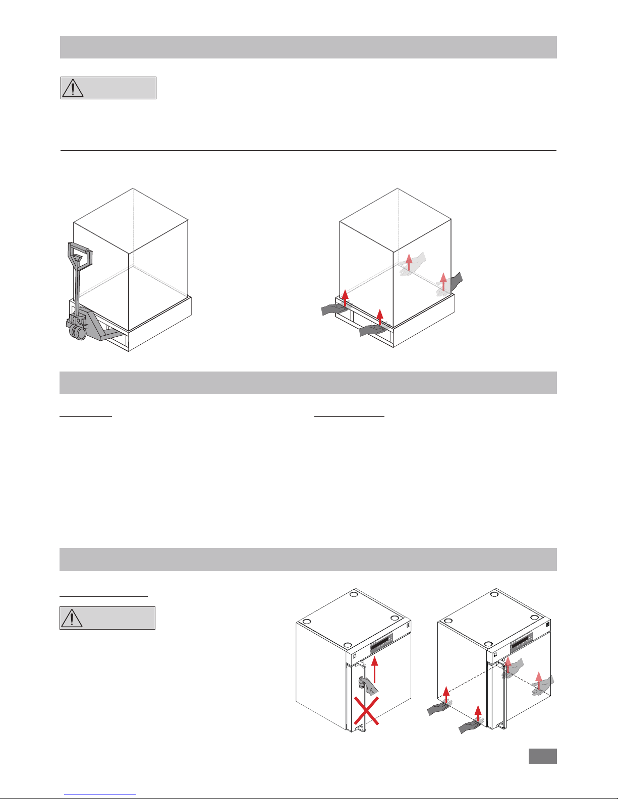
Unpacking.................................................................................................................................................... 7
Unpacking�������������������������������������������������������������������������������������������������������������������������������������������������������������������7
Delivery scope �������������������������������������������������������������������������������������������������������������������������������������������������������������7
Installation ................................................................................................................................................... 7
Moving the device �������������������������������������������������������������������������������������������������������������������������������������������������������7
Setting up��������������������������������������������������������������������������������������������������������������������������������������������������������������������8
Fixing the device to the wall ����������������������������������������������������������������������������������������������������������������������������������������8
Insert shalves ���������������������������������������������������������������������������������������������������������������������������������������������������������������8
Stacking the device������������������������������������������������������������������������������������������������������������������������������������������������������8
Changing the door opening direction ��������������������������������������������������������������������������������������������������������������������������9
Operator panel and display ........................................................................................................................ 10
Setting the temperature limit ..................................................................................................................... 11
Commissioning........................................................................................................................................... 11
Switch on ������������������������������������������������������������������������������������������������������������������������������������������������������������������11
Heating function��������������������������������������������������������������������������������������������������������������������������������������������������������11
Flap open function ����������������������������������������������������������������������������������������������������������������������������������������������������11
Counter and timer function ���������������������������������������������������������������������������������������������������������������������������������������12
Locking the control element ��������������������������������������������������������������������������������������������������������������������������������������12
Menu settings ............................................................................................................................................ 12
Menu structure����������������������������������������������������������������������������������������������������������������������������������������������������������12
Navigation in the menu ���������������������������������������������������������������������������������������������������������������������������������������������12
Operating mode ��������������������������������������������������������������������������������������������������������������������������������������������������������13
Alarm and key tone ���������������������������������������������������������������������������������������������������������������������������������������������������13
Factory reset��������������������������������������������������������������������������������������������������������������������������������������������������������������13
Calibration and adjustment����������������������������������������������������������������������������������������������������������������������������������������13
Interface and output .................................................................................................................................. 15
USB interface�������������������������������������������������������������������������������������������������������������������������������������������������������������15
USB device drivers������������������������������������������������������������������������������������������������������������������������������������������������������15
Command syntax and format�������������������������������������������������������������������������������������������������������������������������������������15
Commands����������������������������������������������������������������������������������������������������������������������������������������������������������������15
Connections between device and external devices �����������������������������������������������������������������������������������������������������16
Maintenance and cleaning ........................................................................................................................ 16
Cleaning��������������������������������������������������������������������������������������������������������������������������������������������������������������������16
Spare parts order�������������������������������������������������������������������������������������������������������������������������������������������������������16
Repair������������������������������������������������������������������������������������������������������������������������������������������������������������������������16
Error codes................................................................................................................................................. 17
Accessories................................................................................................................................................. 17
Technical data ............................................................................................................................................ 18
Warranty .................................................................................................................................................... 18

4
Indicates an (extreme) hazardous situation, which, if not avoided, will result in death,
serious injury�
Indicates a hazardous situation, which, if not avoided, can result in death, serious injury�
Indicates a potentially hazardous situation, which, if not avoided, can result in injury�
Indicates practices which, if not avoided, can result in equipment damage�
Indicates a hazardous situation that cause from a hot surface!
Indicates crushing risk to fingers/hand�
Explication of warning symbols
Safety instructions
CAUTION
WARNING
CAUTION
NOTICE
DANGER
CAUTION
We declare under our sole responsibility that this product corresponds to the regulations 2006/42/EG, 2014/35/EU,
2014/30/EU and 2011/65/EU and conforms with the standards or other normative documents: EN 61010-1,
EN 61010-2-010, EN 61326-1, EN 60529, EN ISO 12100 and DIN 12880�
Declaration of conformity
General information:
•Read the operating instructions completely before
starting up and follow the safety instructions.
•Keep the operating instructions in a place where they can
be accessed by everyone�
•Ensure that only trained staff work with the device�
•Follow the safety instructions, guidelines, occupational
health and safety and accident prevention regulations�
•Set up the device in a spacious area on an even, stable,
clean, non-slip, dry and fireproof surface�
• Do not operate the instrument in explosive atmospheres,
with hazardous substances or under water�
•Protect the device and accessories from bumping and im-
pacting�
•The socket for the mains cord must be easily accessible�
•Socket must be earthed (protective ground contact)�
•The voltage stated on the type plate must correspond to
the mains voltage�
•The device can only be disconnected by pulling out the
mains plug�
•Disconnected the mains plug before attaching or chang-
ing any accessories�
•Secure the device with the anti-tilt device to ensure the
stability while loading and unloading shelves and during
operation� Ensure sucient fixation of anti-tilt bracket, in
particular at stacked arrangement of device�
WARNING
If the mains switch is not with-
in reach when device is operat-
ing, an EMERGENCY STOP
switch that can be easily ac-
cessed must be installed in the
work area.
•Use the supplied anti tilt bracket�
•Fixation against the wall is compulsory!
•Disconnected the mains plug before cleaning, mainte-
nance and transportation of the unit�
NOTICE Coverings or parts that can be re-
moved from the device without the
aid of any tools must be put back
on the device again to ensure safe
operation, for example to keep for-
eign objects and liquids, etc� from
getting into the device�
•The device may only be used as prescribed and as de-
scribed in the operating instructions� This includes opera-
tion by instructed specialist personnel�

5
WARNING
Please pay attention to the
dangerous parts of the device
in Fig. 2.
•This device is not intended for use in a potentially hazard-
ous environment�
DANGER Process pathogenic materials
only in closed vessels under a
suitable fume hood. Please
contact IKA®application sup-
port if you have any question.
•A laboratory oven heats sample according to specified pa-
rameters� This involves hazards due to high temperatures,
fire and general hazards� They remain subject to the judg-
ment and responsibility of the operator� For this reason, it
may become necessary for user to take other precaution-
ary safety measures�
•In case of emergency, turn off the device and then discon-
nect the mains cable from the socket�
WARNING
Beware of hazards due to:
- flammable materials
- combustible media with a
low boiling temperature
- glass vessel breakage
- overfilling of media
- damaged or unsuitable ves-
sels.
•Certain applications and materials may be hazardous� You
should take precautions to prevent contact with, or inha-
lation of, toxic liquids, gases, fumes, vapors or powders�
•Risks may also be posed by biological or microbiological
substances�
•Check the device and accessories for damage before each
use� Do not use damaged components�
•Safe operation is only guaranteed with the accessories de-
scribed in the “Accessories” section�
•Only use IKA®approved accessories!
•Use only original IKA®spare parts!
•The feet of the equipment must be clean and undam-
aged�
CAUTION There is a risk of crush when
opening or closing the door.
Keep your hands away from
squeezing edges.
NOTICE Heavy loads can lead to tilting of
the device� Observe loading recom-
mendations for the shelves�
Never use the device for:
- heating food
- drying living beings
- heating room�
Operation:
•The device will automatically restart in mode B and C fol-
lowing any interruption to the power supply�
WARNING
Do not start up the device if:
- It is damaged
- Cable is damaged.
The temperature limit must be
adjusted so that the maximum
permissible temperature can-
not be exceeded even in the
event of a fault. Check the tem-
perature limit on a regular ba-
sis (see section “Temperature
limit”).
• Secure power cable avoid kinks�
•Check power cables at regular intervals for possible mate-
rial fatigue�
•Mains cable should not get in contact with hot parts�
Transport and Installation:
•
Beware of the high dead weight of the device when trans-
porting�
CAUTION
Ensure that your fingers do not
get crushed when setting
down the device.
•
Insucient ventilation may result in the formation of ex-
plosive mixtures� Only use the device in well ventilated
areas�
Heating:
CAUTION The area around the air outlet
nozzel can get very hot at high
operating temperatures.
•Risk of burning caused by vapour or hot surfaces� Pay at-
tention to the residual heat after switching off�
•Only process and heat up any media that has a flash point
higher than the adjusted temperature limit that has been
set (see section “Technical data“)� The safe temperature
limit must always be set to at least 25 °C lower than the
flash point of the media used�
Maintenance:
•The device must only be opened by trained specialists,
even during repair� The device must be unplugged from
the power supply before opening� Live parts inside the
device may still be live for some time after unplugging
from the power supply�

6
Correct use
Use:
The IKA Oven 125 basic - dry is a drying oven for a wide
range of heating, drying and heating application�
The device may only be used for heating up non-explosive
substances and objects� Do not process substances or ob-
jects that might cause explosive vapor�
Range of use (indoor use only):
- Laboratories - Schools
- Pharmacies - Universities - Industry
This device is suitable for use in all areas except:
- Residential areas�
- Areas that are connected directly to a low-voltage supply
network that also supplies residential areas�
The safety of you cannot be guaranteed:
- If the device is operated with accessories that are not sup-
plied or recommended by IKA®�
- If the device is operated improperly or in contrary to the
IKA®specifications�
- If the device or the printed circuit board are modified by
third parties�
Useful information
Calibration and adjustment:
This menu shows how offset values can be entered after the respective temperatures are approached and with an external
measuring device cross-checked (calibrated)�
[C]
300
250
200
150
100
50
0
3-point calibration and offset
factory calibration
CAL 1
-5K
CAL 3
+5K
CAL 2
+7K resulting offset graph
offset < 10 K
deviation between offset points > 30 K
Individual load and ambient condition might influent the temperature behaviour of the chamber� To compensate that influ-
ence there’s the option to neutralize by using the 3-point calibration and offset function� This function allows the tempera-
ture to be calibrated and adjusted at three different temperature values�
Use a calibrated reference measuring device in case of adjustment�
The operation can be done at a single, or up to three temperature levels:
CAL 1: Temperature calibration and adjustment at low value of temperature�
CAL 2: Temperature calibration and adjustment at medium value of temperature�
CAL 3: Temperature calibration and adjustment at high value of temperature�

7
Moving the device:
When transporting the device
do not use the door handle�
This may damage the device�
The device can be moved:
- with optional accessory (roll stand)�
- on a pallet (transport straps)�
- by hands (4 persons at least)�
Installation
Transportation and storage
Transport the device only by quali-
fied persons with suitable handling
facilities, such as pallet truck and
fork truck!
The device must be protected against mechanical impact,
vibrations, dust deposits and corrosive ambient air during
transportation and storage� It is also important to ensure
that the relative humidity does not exceed 80 %�
The device must be completely emptied before transporta-
tion and storage�
Unpacking
Unpacking:
- Please unpack the device carefully�
- In the case of any damage a detailed report must be
sent immediately (post, rail or forwarder)�
Delivery scope:
- IKA Oven 125 basic - dry
- 2 shelves
- Screwdriver (for adjustment of temperature limit)
- Tilt protection
- Mains cable
- USB cable
- User guide
- Calibrating certification
- Warranty card
- with pallet truck� - by hands / unaided (4 persons)�
The device can be transported:
NOTICE
NOTICE

8
Setting up:
Fixation against the wall is compulsory!
- Place the device on and even, clean, dry and fireproof surface in well-ventilated environment�
- Keep sucient distance to radiators and other heat sources�
- Keep at least 150 mm between walls and the device�
Fixing the device to the wall:
The screws used for fixing is selected according to the wall conditions and is not included�
As indicated in following figures, attach the device to a wall with the tilt protections included with the device�
Fasten the tilt protections to the rear side of the device�
Inserting the shelves:
- Open the door� - Insert the shelves� - Load shelves evenly�
B
Stacking the device:
Never stack more than two devices�
When stacking the device, four persons are required to lift it�
In order to keep enough space, please use stacking adapter recommend by IKA®�
< 150 mm > 150 mm
Stacking
adapter
NOTICE
WARNING
NOTICE

9
Changing the door opening direction:
When changing the door opening direction, two persons are required due to the heavy
(about 15 kg) of the door.
Open the door�
Hold the door and loosen the hinge pin with a suitable tool�
Remove the door carefully�
Alternate the position of the keepers and hinges with 4 mm hexagonal wrench�
Reverse and assemble the door� Make sure that the pin is in the correct position during assembling the door�
+
-
+
-
WARNING

10
Operator panel and display
Item Designation Function
A LED display (temperature): Display the temperature�
B LED display (flap): Display the air flap opening percentage of the venting�
C LED display (Timer/Counter): Display the timer/counter value�
D LED indicator (Counter): Indicate the counter function is activated�
E “Counter/Timer” key: Switch between counter and timer function�
F LED indicator (lock): Indicates that the function of keys is deactivated�
G Lock Key: Lock/unlock keys�
H Timer key: Start the timer function�
I “Start/Stop” key (heating): Start/Stop the heating function�
J LED indicator (Timer): Indicate the timer function is activated�
K “Timer (+)” key: Increase the timer setting value�
Navigation, selecting the settings in the menu�
L “Timer (-)” key: Decrease the timer setting value�
Navigation, selecting the settings in the menu�
M “Flap open (+)” key:
Open the flap vent in 10 % increments�
N “Flap open (-)” key:
Close the flap vent in 10 % increments�
O “Temp (+)” key: Increase the temperature setting value�
Change the setting in the menu�
P “Temp (-)” key: Decrease the temperature setting value�
Change the setting in the menu�
R LED indicator (Actual): The LED lights up at the same time as the actual value is displayed�
S LED indicator (Set): The LED lights up at the same time as the set value is displayed�
T LED indicator (heating): Indicate the heating function is activated�
KM LN J
R
OP
B C D E
G
F
I
A
S
T
H

11
Setting the temperature limit
Adjust the temperature limit (increase the value by clock-
wise / decrease the value by counterclockwise) with screw-
driver delivered with the device�
The temperature limit setting will appear on the display�
Temperature limit
Factory setting: approximate max. value
Adjustment range: see “Technical data“�
WARNING
The safe temperature limit
must always be set to at least
25 °C lower than the flash
point of the media used.
Commissioning
Check whether the voltage specified on the type plate
matches the mains voltage available�
The power socket used must be
earthed (protective earthing)�
If above conditions are met, the device is ready for opera-
tion after plugging in the mains plug�
If these conditions are not met, safe operation is not guar-
anteed and the device could be damaged�
Observe the ambient conditions (temperature, humidity,
etc�) listed under “Technical data”�
Switch on:
After switching on the mains switch (1), all LED segments
light up during the self test�
Starting
Device type Operating mode (A) Software version
Temperature limit
After that, following two screens appear alternatively�
Room temperature
Then the device enters standby status and is ready for op-
eration�
Heating function:
The heating function can be started or stopped by pressing
the “Start/Stop“ key (I)�
When the heating function is activated by pressing the “Start/
Stop“ key (I), the heating indicator (T) lights up�
Then, the target temperature and the actual temperature
appears on display (A) alternately� Accordingly, setting value
indicator (S) or actual value indicator (R) lights up alternately�
The heating temperature can be adjusted by pressing the
“Temp (+)” key (O) or “Temp (-)” key (P)�
By pressing the “Temp (+)” key (O) or “Temp (-)” key (P), the
temperature increase or decrease in 0�1 °C steps�
For changing the temperature more quickly, Keep pressing
on “Temp (+)” key (O) or “Temp (-)” key (P)�
The value could be changed in standby or operation process�
Flap open function:
Change the position of the flap by pressing the falp open
+/- keys (in 10 % increments)�
+
-

12
Menu settings
Menu structure:
Menu
Mode
Alarm and key tone
Factory reset
Info calibration
A
B
C
On
Off
No
Yes
Edit (Edit CALI) Calibration and adjustment C0
C1
C2
C3
Factory setting
activated
-
-
activated
-
activated
-
activated
-
-
-
Info calibration:
In this menu, the current offset values can be viewed�
Edit calibration:
In this menu, the offset values can be entered directly�
Calibration and adjustment:
This menu shows how offset values can be entered after the respective temperatures are approached and with
an external measuring device cross-checked (calibrated)�
Navigation in the menu:
FEnter/leave the menu by pressing ”Counter/Timer” key (E) and “Timer“ key (H)�
FPress the“Timer (+)“ key (K) or “Timer (-)“ key (L) to switch the menu options�
FChange the menu setting by pressing “Temp (+)“ key (O) or “Temp (-)“ key (P)�
F
Save the setting by pressing the “Start/Stop“ key (I)�
Counter and timer function:
Counter function:
When the heating function is started by pressing “Start/
Stop“ key (I), the counter will start automatically and coun-
ter indicator (D) lights up� The counter value shows on dis-
play (C)�
When the operating time is less than 1 day (24 hours), the
counter work with
hour/minute (hh:mm)
mode�
When the operating time is more than 1 day (24 hours), the
display switches from hour/minute mode to day mode� In
the day mode, the display show the day and hour/minute
(hh:mm) alternatively�
When the heating function is stop by pressing “Start/Stop“
key (I), the counter value appear on display (C)�
When the heating function is started again, the counter will
re-start from 00:00�
Note: The maximum counter value is 100 days (d: 99/23:59)�
During counter mode, the “Timer“ key is invalid�
Switching between “Counter” and “Timer” function:
The “Counter” function could be switch to “Timer“ function
by pressing the “Counter/Timer” key (E)”� The timer indica-
tor (J) lights up to indicate the “Timer“ function is activated�
Press the “Counter/Timer” key (E) again, the “Counter“ func-
tion will be activated and counter indicator (D) lights up�
Locking the control elements:
The control elements of the device allow to be locked by
pressing the lock key (G) about 2 seconds, so no accidental
changes during operation are possible (LED (F) lights up)�
By pressing the lock key (G) about 2 seconds again, the con-
trol elements are released (LED (F) no longer lights up)�
Timer function:
The “Timer” can be adjusted by pressing “Timer (+)” key (K)
or “Time (-)” key (L)�
During operating, the “Timer” start increase with hour/min-
ute (hh:mm) mode�
When the timer value reach 24 hours, the display switch
to day mode� The display show the day and hour/minute
(hh:mm) alternatively�
For changing the timer more quickly, Keep pressing on “Tim-
er (+)” key (K) or “Timer (-)” key (L)�
After setting, the timer can be started by pressing “Timer”
key (H)� The heating function stops automatically once this
time has expired� The display (C) blinks “00:00” until you
press any key�
Note: The maximum timer value is 100 days (d: 99/23:59)�
The timer value could be changed in standby or operation
process� When timer function is activated, starting or clos-
ing the heating function by pressing “Start/Stop“ key (I)
doesn’t influence of the timer function�

13
Operating mode:
Mode A: The device doesn’t restart again after power on/
power failure� The setting of heating temperature is adjustable�
Mode B: The device restart again after power on/power
failure� The setting of heating temperature is adjustable�
Mode C: The device restart again after power on/power
failure� The setting of heating temperature is not adjustable�
Alarm and key tone:
Beep on: alarm and key tone is activated�
Beep off: no alarm and key tone�
Factory reset:
No reset�
Reset�
Calibration and adjustment:
The device is calibrated and adjusted in the factory�
Individual sample loading and ambient condition might in-
fluent the temperature behaviour of the chamber� You can
select and make 1-point, 2-point or 3-point calibration and
adjustment as necessary�
By using 3-point calibration to compensate that influence,
the device can get the optimal result� This function allows
the temperature to be calibrated and adjusted to three dif-
ferent temperature values�
When calibration, locate a calibrated reference measuring
sensor at the center of the cabinet�
Calibration information:
In this menu option, you can review the calibration informa-
tion in the device:
Enter the calibration information by pressing “Start/Stop”
key (I) and following screens appear:
If the device is selected 3-point calibration, following cali-
bration information screen will appear:
Back to calibration information screen by pressing “Start/
Stop” key (I)�
By pressing “Timer (+)” key (K) or “Timer (-)” key (L), you can
switch between following three screens and review relate
calibration information:
Edit calibration parameters:
In this menu option, you can edit the calibration parameter
in the device:
Confirm to edit the setting values by pressing “Start/Stop”
key (I) and following screen appear:
By pressing “Temp (+)” key (O) or “Temp (-)” key (P), you can
select following types calibration:
(no adjustment)
(1-point calibration)
(2-point calibration)
(3-point calibration)

14
Calibrate the device:
In this menu option, you can calibrate the device�
Before starting the calibration, locate a reference measuring
temperature sensor at the centre of the cabinet�
Confirm to calibrate the device by pressing “Start/Stop” key
(I) and following screen appear:
Select 2-point calibration by pressing “Temp (+)” key (O)�
Following screen appear:
Confirm the selected calibration type by pressing “Start/
Stop” key (I)�
Switch to the first point calibration screen by pressing “Tim-
er (+)” key (K)�
Set the calibration temperature value by pressing “Temp (+)”
key (O) or “Temp (-)” key (P)�
Set the first point temperature (e�g� 100 ºC) by pressing
“Temp (+)” key (O) or “Temp (-)” key (P)�
Change the reference temperature value by pressing “Temp
(+)” key (O) or “Temp (-)” key (P)�
Example: 2-point calibration:
Switch to calibration screen by pressing “Temp (+)” key (O)
or “Temp (-)” key (P):
Confirm the setting by pressing “Start/Stop” key (I)� The de-
vice start to heat� The set temperature value changes to the
right side of the screen and actual temperature appears on
the left side of the screen:
Wait about 1–2 hours until temperature is stable (e�g� reach
about 98�8 ºC) and “Set“ LED (S) no longer flashes and the
following screen appear:
Input the calibration value from the reference measuring
device (e�g� 98�6 ºC) with “Temp (+)” key (O) or “Temp (-)”
key (P):
Confirm the value by pressing “Start/Stop” key (I)� Then, fol-
lowing screen appear:
Switch to reference temperature screen by pressing “Timer
(+)” key (K)�
Confirm the setting by pressing “Start/Stop” key (I)�
Switch to the other points setting by pressing “Timer (+)”
key (K)�
The other points parameter can be set in the same way�
Back to edit calibration screen by pressing “Start/Stop” key
(I) again after confirming the settings�
Switch to the first point calibration screen by pressing “Timer
(+)” key (K)�
Press “Start/Stop” key (I) again to finish the first point cali-
bration�
The other point calibration can be performed in the same
way�

15
Interface and output
The device can be connected to a PC and operated with the
laboratory software labworldsoft®through USB interface (5)�
Note: Please observe the system requirements as well as
the operating instruction and help section of the software�
USB interface:
The Universal Serial Bus (USB) is a serial bus for connecting
the device to the PC� Equipped with USB devices can be con-
nected to a PC during operation (hot plugging)� Connected
devices and their properties are automatically recognized�
Use the USB interface in conjunction with labworldsoft®for
operation in “Remote” mode and also to update the firm-
ware�
USB device drivers:
First, download the latest driver for IKA®devices with USB
interface from:
http://www.ika.com/ika/lws/download/usb-driver.zip.
Install the driver by running the setup file� Then connect the
IKA®device through the USB data cable to the PC�
The data communication is via a virtual COM port�
Command syntax and format:
The following applies to the command set:
- Commands are generally sent from the computer (Master)
to the device (Slave)�
- The device sends only at the computer’s request� Even
fault indications cannot be sent spontaneously from the
device to the computer (automation system)�
- Commands are transmitted in capital letters�
- Commands and parameters including successive parame-
ters are separated by at least one space (Code: hex 0x20)�
- Each individual command (incl� parameters and data) and
each response are terminated with Blank CR LF (Code:
hex 0x20 hex 0x0d hex 0x20 hex 0x0A) and have a maxi-
mum length of 80 characters�
- The decimal separator in a number is a dot (Code: hex
0x2E)�
The above details correspond as far as possible to the recommendations of the NAMUR working party (NAMUR rec-
ommendations for the design of electrical plug connections for analogue and digital signal transmission on individual
items of laboratory control equipment, rev� 1�1)�
The NAMUR commands and the additional specific IKA®commands serve only as low level commands for communication
between the device and the PC� With a suitable terminal or communications programme these commands can be transmit-
ted directly to the device� The IKA®software package, Labworldsoft®, provides a convenient tool for controlling the device
and collecting data under MS Windows, and includes graphical entry features, for motor speed ramps for example�
Commands Function
IN_PV_2 Read the internal actual temperature
IN_SP_2 Read the internal setting temperature
IN_SP_3 Read the safety setting temperature
IN_SP_4 Read the flap setting
OUT_SP_2 X Set the internal setting temperature, X = 0 to 250
OUT_SP_12@n Setting WD safety limit temperature with set value echo
OUT_SP_4 X Set the flap setting, X = 0 to 100
OUT_WD1@m Watchdog mode 1: if event WD1 should occur, the heating functions are switched off and PC1 is
displayed� Set watchdog time to m (20 - 1,500) seconds, with watchdog time echo� This command
launches the watchdog function and must be transmitted within the set watchdog time�
OUT_WD2@m Watchdog mode 2: if event WD2 should occur, the temperature target value is changed to the
WD safety temperature limit value� The warning PC2 is displayed� The WD2 event can be reset
with OUT_WD2@0 - this also stops the watchdog function� Set watchdog time to m (20 - 1,500)
seconds, with watchdog time echo� This command launches the watchdog function and must be
transmitted within the set watchdog time�
START_2 Start the heating function
STOP_2 Stop the heating function
RESET Switches off the device function
Note: when disconnecting the USB cable while the device is running, the device stays in PC mode� To reset to function
without PC, switch the device off and on again�

16
USB B USB A
1
4
3 2
1
2
3
4
“Watchdog” function, monitoring the serial data flow:
The following applies to situations where the watchdog function is enabled (see Namur instructions)� If no new transmissions
of these commands from the PC take place within the preset watchdog time, the heating function will be shutdown
according to the watchdog mode selected or will be controlled using the preset setpoints� An operating system crash, a PC
power failure or a fault in the connecting cable to the device can cause an interruption in data transmission�
“Watchdog”– Mode 1
If an interruption in data transmission occurs which is longer than the preset watchdog time, the heating function will be
shutdown and the error message PC 1 will be displayed�
“Watchdog”– Mode 2
If an interruption in data transmission occurs which is longer than the preset watchdog time, the temperature setpoint will
be set to the WD safety temperature setpoint� The PC 2 warning message will be displayed�
Connections between device and external devices:
USB 2�0 cable A - B:
This cable is required to connect USB interface to a PC�
Maintenance and cleaning
The device is maintenance-free� It is only subject to the natural
wear and tear of components and their statistical failure rate�
Cleaning:
For cleaning disconnect the mains
plug!
Use only cleaning agents which have been approved by
IKA®to clean IKA®devices�
Dirt Cleaning agent
Dye Isopropyl alcohol
Construction
material
Water containing tenside/isopropyl alcohol
Cosmetics
Water containing tenside/isopropyl alcohol
Foodstuff Water containing tenside
Fuel Water containing tenside
- For materials which are not listed, please request infor-
mation from IKA®application support�
- Wear protective gloves while cleaning the device�
- Electrical devices may not be placed in the cleansing agent
for the purpose of cleaning�
- Do not allow moisture to get into the device when cleaning�
- If a different cleaning or decontamination method than
the method defined by IKA®is planned, you must ascer-
tain with IKA®that this method does not damage the
device�
Spare parts order:
When ordering spare parts, please give:
- Machine type�
- Serial number, see type plate�
-
Item and designation of the spare part,
s
ee www.ika.com, spare parts diagram and list
�
Repair:
Please send the device for repair only after it has
been cleaned and is free from any materials which
may constitute a health hazard.
For repair, please request the “Decontamination Certificate”
from IKA®, or download printout of it from the IKA®web-
site www.ika.com�
If you require servicing, return the device in its original pack-
aging� Storage packaging is not sucient� Please also use
suitable transport packaging�

17
Error codes
Any malfunctions during operation will be identified by an error message on the display�
Proceed as follows in such cases:
FSwitch off device using the main switch at front of the device�
FCarry out corrective measures�
FRestart device�
Error code Cause Effect Solution
Er 03 Temperature inside device (PCB power) too high Heating off - Switch off device and allow it to
cool down�
Er 06 Set temperature limit exceeded Heating off - Contact IKA®service department�
Er 21 Safety relay does not open Heating off - Contact IKA®service department�
Er 25 Heater1 error Heating off - Contact IKA®service department�
Er 26 Heater2 error Heating off - Contact IKA®service department�
Er 27 No internal sensor Heating off - Contact IKA®service department�
If the actions described fails to resolve the fault or another error code is displayed then take one of the following steps:
- Contact the service department
- Send the device for repair, including a short description of the fault�
Accessories
USB 2.0 cable A - B Labworldsoft®
See more accessories on www.ika.com.

18
Warranty
In accordance with IKA®warranty conditions, the warranty
period is 24 months� For claims under the warranty please
contact your local dealer� You may also send the machine
direct to our factory, enclosing the delivery invoice and giving
reasons for the claim� You will be liable for freight costs�
The warranty does not cover worn out parts, nor does it ap-
ply to faults resulting from improper use, insucient care or
maintenance not carried out in accordance with the instruc-
tions in this operating manual�
Technical data
Operating voltage VAC 230 ± 10 %
115 ± 10 %
100 ± 10 %
Frequency Hz 50/60
Max� input power W2450 (230 V)
1550 (115 V)
1200 (100 V)
Heating power W2400 (230 V)
1500 (115 V)
1150 (100 V)
Heating temperature range °C RT + 5 ��� + 250
Temperature limit °C + 50 ��� + 270
Resolution of temperature adjusting K0�1
Temperature stability (at 150 °C) K± 0�3
Temperauture display LED
Timer/countuer function Yes
Timer/countuer display LED
Max� timer / counter 100 days (
d: 99/23:59 [hh:mm]
)
Max� number of tray 6
Max� load for one tray kg 30
Interface USB
Permissible ambient temperature °C + 5 ��� + 40
Permitted ambient humidity %80
Permitted on-time %100
Protection class according to EN 60 529 IP 20
Protection class I
Overvoltage category II
Contamination level 2
Dimensions (W x D x H) mm 700 x 650 (+ 75 with hand grip) x 825
Inside dimensions (W x H x D) mm 550 x 525 x 450
Internal volume l125
Weight kg 55
Operation at a terrestrial altitude mmax� 2000
Note: Complies to EN61000-3-11 subject to conditional connection: Zmax = 0�362 Ω� If necessary, consult your electricity
supplier�
Subject to technical changes!

IKA®-Werke GmbH & Co.KG
Janke & Kunkel-Str� 10
D-79219 Staufen
Tel� +49 7633 831-0
Fax +49 7633 831-98
sales@ika�de
www.ika.com
Other manuals for Oven 125 basic dry
1
Table of contents
Other IKA Laboratory Equipment manuals

IKA
IKA RW 16 basic User manual

IKA
IKA Roller 6 basic User manual

IKA
IKA RH basic User manual

IKA
IKA HABITAT User manual

IKA
IKA A 11 basic User manual

IKA
IKA Roller 6 digital User manual

IKA
IKA RV 8 User manual

IKA
IKA Big Squid User manual

IKA
IKA KS 3000 i control User manual

IKA
IKA Plate RCT digital User manual
Popular Laboratory Equipment manuals by other brands

Phcbi
Phcbi MDF-U334 Series operating instructions

IML
IML SLIDEFEEDER X80 manual

Thermo Scientific
Thermo Scientific 88882015 operating manual

Cole Parmer
Cole Parmer EH-200 Series instruction manual

Dräger
Dräger DrugCheck 3000 Instructions for use

Waters
Waters Xevo G2-XS QTof Overview and maintenance guide