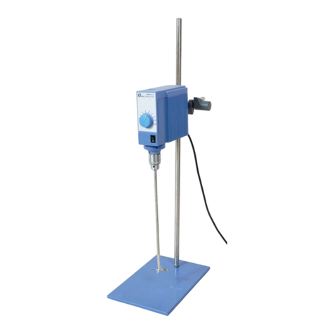
IKA RW 47 D User manual

IKA®WERKE
RW47D012004
BETRIEBSANLEITUNG D 4
OPERATING INSTRUCTIONS GB 11
MODE D’EMPLOI F18
11 797 00
Reg.-No. 4343-01
IKA
®
IKA®
RW 47 D
RW 47 D_def 09.02.2004 14:54 Uhr Seite 1

M
[Nm]
Drehzahl der Abtriebswelle
55
50
35
40
Drehmoment der Abtriebswelle
30
25
20
15
10
5
0200 400 600 800
Arbeitsbereich
Getriebestufe I
Arbeitsbereich
Getriebestufe II
1000 1200 1400 n [1/min]
2RW47D102003
Fig. 1
1100
50Hz
60Hz
100 150 200 250 300 500 700 900
1300
••••• •••• •
300
•
100
•150
•200 •
250
•
1500
•
500
•700
•900
•
1100
•
1300
•
IKA®RW 47 D
Nur im Stillstand umschalten / reverse at standstill only
Drehrichtung
O
III
Anschluss-Netz
connection-power supply
Anschluss-Sicherheitsendschalter
connection-limit switch
Taster I EIN (grün)
bush-button I ON (green)
(A)
Knebel
toggle
(D)
Taster O AUS/RESET (rot)
bush-button O = OFF/RESET (red)
(B)
Drehknopf
rotary control knob
(C)
Spannfutter
chuck
(Ø 3-16mm)
(E)
Knebel
toggle
n [1/min]
400 600 800 1000 1200
Drehzahl der Abtriebswelle
5
10
Drehmoment der Abtriebswelle
M
[Nm] Grenzkurve Getriebestufe II
200100 n [1/min]
10
20
30
4040
Grenzkurve Getriebestufe I
M
[Nm]
50
Drehmoment der Abtriebswelle
Fig. 2
RW 47 D_def 09.02.2004 14:54 Uhr Seite 2

3
RW47D102003
CE-KONFORMITÄTSERKLÄRUNG D
Wir erklären in alleiniger Verantwortung, daß dieses Produkt den Bestimmungen der
Richtlinien 89/336EG und 73/023EG entspricht und mit den folgenden
Normen und norminati-
ven Dokumenten übereinstimmt: EN 61010-1; EN 60204-1; EN 292-1, -2; EN 414 und EN 61326-1.
CE-DECLARATION OF CONFORMITY GB
We declare under our sole responsibility that this product corresponds to the regulations
89/336EEC, 89/392EEC and 73/023EEC and conforms with the standards or standardized
documents
EN 61010-1; EN 60204-1; EN 292-1, -2; EN 414; EN 55011; EN 55014, EN 50081, EN
50082-1, EN 60555-2, -3.
DÉCLARATION DE CONFORMITÉ CE F
Nous déclarons sous notre propre responsabilité que ce produit est conforme aux réglemen-
tations 89/336CEE, 89/392CEE et 73/023CEE et en conformité avec les normes ou docu-
ments normalisés suivant
EN 61010-1; EN 60204-1; EN 292-1, -2; EN 414; EN 55011; EN 55014,
EN 50081, EN 50082-1, EN 60555-2, -3.
DECLARACION DE CONFORMIDAD DE CE E
Declaramos por nuestra responsabilidad propia que este producto corresponde a las directri-
ces 89/336CEE, 89/392CEE y 73/023CEE y que cumple las normas o documentos normativos
siguientes:
EN 61010-1; EN 60204-1; EN 292-1, -2; EN 414; EN 55011; EN 55014, EN 50081, EN
50082-1, EN 60555-2, -3.
CE-CONFORMITEITSVERKLRING NL
Wij verklaren in eigen verantwoordlijkheid, dat dit produkt voldoet ann de bepalingen van de
richtlijnen 89/336EEG, 89/392EEG and 73/023EEG en met de volgende normen
of normatieve
dokumenten overeenstemt: EN 61010-1; EN 60204-1; EN 292-1, -2; EN 414; EN 55011; EN 55014,
EN 50081, EN 50082-1, EN 60555-2, -3.
CE-DICHIARAZIONE DI CONFORMITÀ I
Dichiariamo, assumendone la piena responsabilità, che il prodotto è conforme alle seguenti
direttive: CCE 89/336, CCE 89/392 e CCE 73/023, in accordo ai seguenti regolamenti e docu-
menti:
EN 61010-1; EN 60204-1; EN 292-1, -2; EN 414; EN 55011; EN 55014, EN 50081, EN 50082-
1, EN 60555-2, -3.
CE-KONFORMITETSFÖRKLARUNG S
Vi förklarar oss ensamt ansvariga för att denna produkt motsvarar bestämmelserna i riktlinjer-
na 89/336EEG, 89/392EEG och 73/023EEG och att den överensstämmer med
följande normer
eller normativa dokument: EN 61010-1; EN 60204-1; EN 292-1, -2; EN 414; EN 55011; EN 55014,
EN 50081, EN 50082-1, EN 60555-2, -3.
CE-KONFORMITETSERKLÆRING DK
Vi erklærer, at dette produkt öpfylder bestemmelserne i direktiverne 89/336EØF, 89/392EØF
og 73/023EØF og at det er overensstemmende med følgende normer eller normgivende
dokumenter:
EN 61010-1; EN 60204-1; EN 292-1, -2; EN 414; EN 55011; EN 55014, EN 50081, EN
50082-1, EN 60555-2, -3.
CE-KONFORMITETSERKLÆRING N
Vi erklærer på helt og holdent eget ansvar at dette produktet er i samsvar med bestemmelsene i
forskriftene 89/336EEG, 89/392EEG og 73/023EEG, og at de er i overensstemmelse med følgende
normer eller normative dokumenter: EN 61010-1; EN 60204-1; EN 292-1, -2; EN 414; EN 55011; EN
55014, EN 50081, EN 50082-1, EN 60555-2, -3.
CE-STANDARDINMUKAISUUSTODISTUS SF
Ilmoitamme täysin omalla vastuullamme, että tämä tuote vastaa EU-direktiivejä 89/336EU ,
89/392EU sekä 73/023EU ja on seuraavien normien tai ohjeasiakirjojen mukainen: EN 61010-1; EN
60204-1; EN 292-1, -2; EN 414; EN 55011; EN 55014, EN 50081, EN 50082-1, EN 60555-2, -3.
∆ΗΛΩΣΗ ΑΝΤΑΠΟΚΡΙΣΗΣ ΕΕ GR
Με την παρούσα δήλωση βεβαιώνουνε µε αποκλειστική µας ευθύνη τι
το παρν προϊν ανταποκρίνεται στους κανονισµούς των οδηγιών 89/336
Ε.Ο.Κ., 89/392 Ε.Ο.Κ. και 73/023, και τι αντιστοιχεί στις ακλουθες
προδιαγραφές και στα ακλουθα νοµοκανονιστικά έγγραφα
EN 61010-1; EN
60204-1; EN 292-1, -2; EN 414; EN 55011; EN 55014, EN 50081, EN 50082-1, EN 60555-2, -3.
DECLARAÇÃO DE CONFORMIDADE DA CE P
Declaramos sob nossa responsabilidade exclusiva que este produto corresponde às determinações
estabelecidas nas directivas 89/336 CEE, 89/392 CEE e 73/023 CEE do Conselho e que está de
acordo com as seguintes normas e documentos normativos: EN 61010-1; EN
60204-1; EN 292-1, -
2; EN 414; EN 55011; EN 55014, EN 50081, EN 50082-1, EN 60555-2, -3.
IKA LABORTECHNIK Janke & Kunkel GmbH & CO. KG
Staufen, Oktober 2003
Wolfgang Buchmann
Corporate Director - Quality Assurance
Reiner Dietsche
Vice President
RW 47 D_def 09.02.2004 14:54 Uhr Seite 3

Seite
Sicherheitshinweise 4
Bestimmungsgemäßer Gebrauch 5
Auspacken 5
Wissenswertes 6
Antrieb 6
Motorschutz 6
Drehzahlanzeige 7
Getriebeumschaltung 7
Inbetriebnahme 7
Einschalten des Gerätes 8
Abtriebswelle 8
Wartung und Reinigung 8
Technische Daten 9
Zubehör 10
Zulässige IKA-Rührwerkzeuge 10
Angewandte Normen und Vorschriften 10
Garantie 10
Verdrahtungsplan 77
Ersatzteilliste 78
Ersatzteilbild 79
Betreiben Sie das Gerät niemals mit frei rotierendem Rührwerk-
zeug. Achten Sie darauf, dass Körperteile, Haare oder Kleidungs-
stücke nicht von rotierenden Teilen erfaßt werden können.
Richten Sie Ihre Aufmerksamkeit beim Einstellen der Drehzahl
auf Unwuchten des Rührwerkzeuges und mögliches Spritzen
des zu rührenden Mediums. Verwenden Sie eine
Rührwellenschutzeinrichtung und eine Sicherheitsabschaltung
für höhenverstellbare Stative!
Das Gerät ist nicht für Handbetrieb geeignet. Bitte beachten Sie
einschlägige Sicherheitshinweise und Richtlinien, sowie
Arbeitsschutz- und Unfallverhütungsvorschriften für den Einsatz
im Labor. Der Anwender muss beim Arbeiten mit dem Rührgerät
seine persönliche Schutzausrüstung entsprechend der zu
mischenden Gefahrenklasse wählen und tragen. Bei defekter
oder unangemessener Schutzausrüstung kann der Anwender
durch Spritzen oder Hereinziehen am Rührwerkzeug gefährdet
werden.
Im Betrieb ist zu beachten, dass die Motoroberflächen (Kühlrip-
pen) und besondere Wälzlagerstellen sehr warm werden kön-
nen.
Vermeiden Sie Stöße und Schläge auf das untere Wellenende
bzw. Zahnkranzfutter. Bereits kleine, nicht erkennbare Schäden
führen zu Unwucht und unrundem Lauf der Welle. Sorgsame
Behandlung garantiert sicheres Arbeiten und Langlebigkeit des
Gerätes.
Unwuchten der Abtriebswelle, des Futters und insbesondere der
Rührwerkzeuge können zu unkontrolliertem Resonanzverhalten
des Gerätes und des gesamten Aufbaues führen. Dabei können
Glasapparaturen und Rührgefäße beschädigt oder zerschlagen
werden. Dadurch und durch das rotierende Rührwerkzeug kann
der Anwender verletzt werden. Wird ein unruhiger Lauf des
Gerätes bemerkt, muss auf jeden Fall die Drehzahl soweit redu-
ziert werden, bis keine Laufunruhen mehr auftreten. Tauschen
Sie in diesem Fall das Rührwerkzeug gegen ein Werkzeug ohne
Unwucht aus bzw. beseitigen Sie die Unwuchtursache.
Der Betrieb mit frei rotierendem Rührwerkzeug ohne Rührgefäß
ist gefährlich. Die Rührwerkzeuge dürfen nur so tief in die
Hohlwelle gesteckt werden, dass ein Schleifen an der
Gehäuseoberkante ausgeschlossen ist. Achten Sie darauf, dass
das Rührwerkzeug fest im Spannfutter eingespannt ist.
Das Umschalten in eine andere Zahnrad-Getriebestufe darf nur
bei ausgeschaltetem Gerät erfolgen. Andernfalls werden die
Zahnräder der Zahnrad-Getriebestufe beschädigt.
4RW47D102003
Inhaltsverzeichnis
Sicherheitshinweise
RW 47 D_def 09.02.2004 14:54 Uhr Seite 4

5
RW47D102003
den Betrieb unter Wasser eingesetzt werden.
Im Betrieb nicht an drehende Teile fassen!
Verwenden Sie nur IKA - Zubehör.
Das Zubehör darf nur nach Ziehen des Netzsteckers montiert
werden.
Verwenden Sie eine Rührwellenschutzeinrichtung und eine
Sicherheitsabschaltung für höhenverstellbare Stative.
Das Rührwerk RW 47D eignet sich durch Verwendung
unterschiedlicher Rührorgane zum Rühren und Mischen von
Flüssigkeiten mit niedriger bis hoher Viskosität. Es ist für den
Einsatz im Technikum und für Kleinproduktion konzipiert. Zum
bestimmungsgemäßen Gebrauch muss das Gerät sorgfältig mit
vier Schauben (siehe Fig. 2) an einem Stativ befestigt werden.
Außerdem muß darauf geachtet werden, daß die
Befestigungseinrichtung (z.B. Bodenstativ, Teleskopstativ)
kippsicher aufgestellt wird und während des Rührvorganges
nicht zu wandern beginnt.
Bitte packen Sie das Gerät vorsichtig aus und achten Sie auf
Beschädigungen. Es ist wichtig, daß eventuelle Transport-
schäden schon beim Auspacken erkannt werden.
Gegebenenfalls ist eine sofortige Tatbestandsaufnahme
erforderlich (Post, Bahn oder Spedition).
Zum Lieferumfang des Gerätes gehören:
Ein RW 47 D Rührgerät entsprechend der bestellten Type, ein
Spannfutterschlüssel, Winkelschraubendreher, Innensechskant-
schrauben und eine Betriebsanleitung.
Das Gerät darf - auch - im Reparaturfall nur von einer Fachkraft
geöffnet werden. Vor dem Öffnen ist der Netzstecker zu ziehen.
Spannungführende Teile im Innern des Gerätes können auch län-
gere Zeit nach Ziehen des Netzsteckers noch unter Spannung
stehen.
Das hohe Drehmoment des RW 47 D erfordert eine spezielle
Sorgfalt bei der Wahl des Stativs und der Verdrehsicherung für
den Rührbehälter.
ACHTUNG ! Abdeckungen bzw. Teile die ohne
Hilfsmittel vom Gerät entfernt werden können,
müssen zum sicheren Betrieb wieder am Gerät an-
gebracht sein, damit zum Beispiel das Eindringen
von Fremdkörpern, Flüssigkeiten etc. verhindert wird.
Die für den Rührvorgang verwendeten Rührgefäße müssen
befestigt werden.
Wird das Rührgerät so betrieben, dass der NOT-AUS Schalter am
Gerät nicht erreichbar ist, muss dafür gesorgt werden, dass ein
zusätzlicher gut erreichbarer NOT-AUS Schalter im Arbeits-
bereich angebracht wird.
Zusätzliche Gefährdungen für den Anwender können auftreten,
wenn beim Rührvorgang entzündliche Materialien verwendet wer-
den oder wenn bei Verwendung von Glaseinrichtungen die über-
tragene mechanische Rührorganenergie zum Glasbruch führt.
Achten Sie vor Inbetriebnahme des Gerätes darauf, daß die klein-
ste Drehzahl eingestellt ist, da das Gerät ansonsten mit der
zuletzt eingestellten Drehzahl zu laufen beginnt. Das Rühren mit
hohen Drehzahlen kann dazu führen, dass das Medium aus dem
Mischbehälter spritzt. Zwischen dem Medium und der
Abtriebswelle kann nicht ausgeschlossen werden, dass elek-
trostatische Vorgänge ablaufen und zu einer Gefährdung führen.
Nach einer Unterbrechung der Stromzufuhr oder einer mechani-
schen Unterbrechung während eines Rührvorganges läuft das
Gerät nicht von selbst wieder an.
Das Rührgerät RW 47 D darf nicht für den Betrieb in explosions-
gefährdeten Atmosphären, zum Mischen von Gefahrstoffen und
Bestimmungsgemäßer Gebrauch
Auspacken
RW 47 D_def 09.02.2004 14:54 Uhr Seite 5

Mit diesem Gerät haben Sie ein qualitativ hochwertiges Produkt
erworben. Durch die robuste Gerätekonstruktion und die
einfache Handhabung ist problemloses Arbeiten gewährleistet.
Mit der Gerätevariante für 50Hz (Netzfrequenz) können
Drehzahlen von 57 bis 1300 1/min und mit der Gerätevariante für
60Hz (Netzfrequenz) die Drehzahlen 69 bis 1560 1/min
eingestellt werden. Das Gerät erwärmt sich während des
Betriebes. Die großzügig gestalteten Kühlflächen am Motor
bewirken möglichst gleichmäßige Verteilung und Abstrahlung
der Wärme.
In Verbindung mit den von IKA hergestellten Stativtypen kann
problemlos auch mit hochaufbauenden Mischbehältern
gearbeitet werden.
Das Gerät wird ohne Anschlusskabel ausgeliefert, weil die
Installationen beim Anwender auf Grund der unterschiedlichen
Räumlichkeiten eine einheitliche Kabellänge nicht zulässt. Im
Verdrahtungsplan ist die Anschlussbelegung für eine Fachkraft
ersichtlich.
Die Präzisionswelle ist als Hohlwelle ausgebildet und ermöglicht
das Durchstecken von Rührerschäften bis zu einem Durch-
messer von 13mm. Hierbei muß darauf geachtet werden, dass
dies nur bis kurz vor die Gehäuseoberkante erfolgen darf.
Außerdem ist darauf zu achten, daß der Rührerschaft fest im
Spannfutter eingespannt ist.
Die Betriebsweise des Motors ist charakteristisch für das
Betriebsverhalten des RW 47D. Der Motor kann stufenlos über
einem Reibradgetriebe verschoben werden und wird nur in
einem Arbeitspunkt betrieben. Motorabgabeleistung, Motor-
drehzahl und Motordrehmoment werden als konstant
angesehen und sind auf diesen Betriebspunkt hin optimiert.
Nach dem Reibradgetriebe wird die Motorabgabeleistung
wahlweise über die erste oder zweite Stufe des
nachgeschalteten handverstellbaren Zahnradgetriebes an die
Abtriebswelle des Rührgerätes weitergegeben.
Die Leistung an der Abtriebswelle ist bei Vernachlässigung aller
Verluste, während der Energieübertragung (Wandlung) immer so
groß, wie die vom Motor abgegebene Leistung. Im Getriebe
erfolgt lediglich eine Drehzahl- und Drehmomentwandlung, die
sich rein theoretisch in der in Fig. 1 dargestellten Kennlinie
beschreiben läßt.
Der Reibradverschleiß wird durch eine an das Getriebe
angepasste Schraubenkupplung klein gehalten. Die am Reibrad
notwendige Reibrad-Anpresskraft wird von der Schrauben-
kupplung entsprechend dem an der Rührwelle wirkenden
Momentenverlauf aus geregelt. Bei einem kleinen Drehmoment
wirkt eine kleine Anpresskraft; bei einem großen Drehmoment
wirkt eine große Anpresskraft.
Der kugelgelagerte Drehstrommotor ist wartungsfrei. Er trägt in
seinem angebauten Schaltkasten eine spezielle Sicher-
heitseinrichtung für den Betrieb bei Überstrom und
Unterspannung (Unterspannungsauslöser) um den Motor
bleibend abzuschalten und eine thermische Beschädigung zu
vermeiden. Das Gerät kann erst dann wieder, durch Betätigen
des EIN/AUS – Schalters (Fig. 2), in Betrieb genommen werden,
wenn die für den Motor zulässige Energieversorgung hergestellt
ist.
Die für den Motor zugrundeliegenden Anschluß und Be-
messungsdaten können dem Leistungsschild auf dem Motor
entnommen werden.
Außerdem ist in dem Motorschaltkasten die Anschluss-
möglichkeit für den Sicherheitsendschalter SI 400 vorgesehen,
6RW47D102003
Wissenswertes
Antrieb
Motorschutz
RW 47 D_def 09.02.2004 14:54 Uhr Seite 6

der dem Anwender, in Verbindung mit einem IKA-Stativ, das
Einschalten des Gerätes auf nur einer definierten Höhe im
Arbeitsbereich der Stative ermöglicht.
Wird das Rührgerät so betrieben, dass der NOT-AUS Schalter (
(B)-Fig. 2) am Gerät nicht erreichbar ist, muß dafür gesorgt
werden, daß ein zusätzlicher gut erreichbarer NOT-AUS Schalter
im Arbeitsbereich angebracht wird.
Die Drehzahl wird beim RW 47D Rührgerät über den seitlichen
Drehknopf (C) eingestellt.
Auf dem auf der Motorauflage angebrachten Schild kann über
die Markierung am Gehäuseoberteil die eingestellte Drehzahl
abgelesen werden. (Die Werte gelten nur bei geringer Belastung
an der Rührwelle).
Mit dem Knebel Knopf (D) auf der Frontseite des Gerätes, kann
eine der drei zur Verfügung stehenden Getriebestellungen (0, I
oder II) ausgewählt werden. Das Umschalten in eine andere
Zahnrad-Getriebestufe darf nur bei ausgeschaltetem Gerät
(Motorstillstand) erfolgen. Andernfalls können die Getriebe-
zahnräder beschädigt werden. Der Pfeil auf dem Frontschild
beschreibt die Drehrichtung des Spannfutters.
Das Rührwerk RW 47D muß zum bestimmungsgemäßen
Gebrauch mit vier Schrauben an einem stabilen Stativ ( z.B. R474
od. R472 ) befestigt und entsprechend dem Verdrahtungsplan
verdrahtet werden. Der
Rührbehälter muss aus
Sicherheitsgründen immer
gut
fixiert
sein.
Aus-
ser-
dem
muss
darauf
ge-
achtet
werden,
dass
die Befestigungs-
einrichtung (z.B.
Bodenstativ, Teles-
kopstativ) kippsicher
aufgestellt wird und
während des Rühr-
vorganges nicht zu
wandern beginnt.
Das Zubehör ist ent-
sprechend den
Montageanleitun-
gen zu montieren
und zu verdrahten.
Wird das Rührgerät so betrieben, dass der NOT-AUS Schalter
((B)-Fig. 2) am Gerät nicht erreichbar ist, muß dafür gesorgt
werden, daß ein zusätzlicher gut erreichbarer NOT-AUS Schalter
im Arbeitsbereich angebracht wird.
Besondere Gefahrenstellen (wie z. Bsp. Quetschen, rotierende
Teile, Feststellschrauben für Stativsäule und Rollen usw.) sind in
Fig. 3 mit einem Ausrufezeichen gekennzeichnet! Im Betrieb ist
auf die Gefahrenstellen im Besonderen zu achten!
7
RW47D102003
Drehzahlanzeige
Getriebeumschaltung
Inbetriebnahme
Fig. 3
RW 47 D_def 09.02.2004 14:54 Uhr Seite 7

werden. Es ist darauf zu achten, daß der Rührerschaft fest im
Spannfutter eingespannt ist.
Das Rührwerk arbeitet wartungsfrei. Es unterliegt lediglich der
natürlichen Alterung der Bauteile und deren statistischer
Ausfallrate.
Bei Ersatzteilbestellungen geben Sie bitte die auf dem
Typenschild angegebene Fabrikationsnummer, den Gerätetyp
sowie die Positionsnummer die Bezeichnung des Ersatzteiles an.
Bitte senden Sie nur Geräte zur Reparatur ein, die gereinigt und
frei von gesundheitsgefährdenden Stoffen sind. Reinigen Sie
IKA-Geräte nur mit von IKA freigegebenen Reinigungsmittel.
Verwenden Sie zum Reinigen von:
Farbstoffen Isopropanol
Baustoffen Tensidhaltiges Wasser / Isopropanol
Kosmetika Tensidhaltiges Wasser / Isopropanol
Nahrungsmitte Tensidhaltiges Wasser
Brennstoffe Tensidhaltiges Wasser
Bei nichtgenannten Stoffen fragen Sie bitte bei IKA nach. Tragen
Sie zum Reinigen der Geräte Schutzhandschuhe. Elektrische
Geräte dürfen zu Reinigungszwecken nicht in das
Reinigungsmittel gelegt werden. Bei der Reinigung des Gerätes
ist besonders darauf zu achten, daß auf die Laufflächen der
Kegelscheibe und des Reibrades keine öl- oder fetthaltige Stoffe
gelangen. Dies würde den aus der Werkstoffpaarung
Reibrad/Kegelscheibe resultierenden Reibkoeffizient erheblich
verkleinern und dadurch die Leistungsübertragung
beeinträchtigen.
Achten Sie darauf, dass der Gewindestift (Pos.153 – Ersatzteil-
bild) ausreichend angezogen ist um ein selbständiges
Verschieben der Motorplatte und somit der Drehzahl zu
vermeiden.
8RW47D102003
Überprüfen Sie, ob die auf dem Typenschild angegebene
Spannung mit der verfügbaren Netzspannung übereinstimmt.
Die verwendete Steckdose muß geerdet sein (Schutz-
leiterkontakt). Wenn diese Bedingungen erfüllt sind, ist das Gerät
nach Einstecken des Netzsteckers betriebsbereit. Andernfalls ist
sicherer Betrieb nicht gewährleistet oder das Gerät kann
beschädigt werden.
Beim Arbeiten mit dem Sicherheitsendschalter SI 400 beginnt
das Gerät erst zu laufen, wenn das Gerät in die vorgesehene
Arbeitshöhe gebracht wurde und der Schaltkontakt den
Sicherheitsendschalter betätigt.
Beim Inbetriebnahme des Gerätes beginnt dieses mit der zuletzt
eingestellten Drehzahl zu laufen. Überprüfen Sie daher vor dem
Einschalten die Stellung der Motorauflage (Drehzahl).
Vergewissern Sie sich auch, daß die eingestellte Drehzahl für
den gewählten Versuchsaufbau unbedenklich ist. Im Zweifelsfall
stellen Sie den Motorschlitten mit Hilfe des seitlichen Drehknopf
auf die kleinste Drehzahl (vorderer Motorschlitten-Anschlag) ein
und das Getriebe auf die kleinste Getriebestufe (Fig. 2).
Durch Drücken des EIN – Schalters am Motor (Fig. 2) beginnt
das Gerät zu laufen.
Wenn das Gerät einige Zeit nicht benutzt wurde, kann nach dem
Einschalten, bedingt durch die Vorspannkraft am Reibbelag des
Reibradgetriebes, ein Klopfgeräusch zu hören sein. Für die
Funktion des Gerätes ist dies nicht von Bedeutung. Das
Klopfgeräusch verliert sich nach einer kurzen Einlaufzeit.
Spannfutter ((E) – Fig. 2) und Abtriebswelle gestatten das Ein-
spannen der Rührwerkzeuge von 3mm bis 16mm Schaft-
durchmesser. Schaftdurchmesser bis 13mm können durch die
Hohlwelle bis kurz vor die innere Gehäuseoberkante gesteckt
Abtriebswelle
Einschalten des Gerätes
Wartung und Reinigung
RW 47 D_def 09.02.2004 14:54 Uhr Seite 8

Drehzahlbereich
50Hz Stufe I 1/min 57 - 275
50Hz Stufe II 1/min 275 – 1300
60Hz Stufe I 1/min 69 - 330
60Hz Stufe II 1/min 330 – 1560
Max. Drehmoment Rührwelle (Überlast) Ncm 4642 ( bei 57 1/min )
Max. Drehmoment Rührwelle Ncm 3000 ( bei 100 1/min )
Max. Drehmoment Rührwelle Ncm 285 ( bei 1000 1/min )
zul. Einschaltdauer: % 100
Drehzahleinstellung: - seitlicher Drehknopf, mechanisch
Drehzahlanzeige: - Skala auf Geräteseite
Motordaten
Bemessungsspannung VAC 3x400 Y 3x230 ∆3x400 Y 3x230 ∆
Bemessungsfrequenz Hz 50 50 60 60
Motordrehzahl 1/min 2880 2850 3425 3425
Aufnahmeleistung W 554 548 489 490
Abgabeleistung W 370 370 370 370
max. Abgabeleistung an der Rührwelle: W 300
Gesamtwirkungsgrad: % 54
Schutzart nach DIN EN 60529: - IP 44
Überspannungskategorie: - II
Schutzklasse - I (Schutzerde)
Verschmutzungsgrad: - 2
Schutz bei Überlast: - Überstrom- und Unterspannungschalter am Drehstrommotor
Zul. Umgebungstemperatur: °C +5 bis+40
Zul. Relative Feuchte % 80
Betriebslage: - am Stativ, Spannfutter nach unten gerichtet
Antrieb: - Rippengekühlter Drehstrommotor mit Reibradgetriebe und
nachgeschaltetem 2 stufigem Zahnradgetriebe.
maximale Rührmenge (Wasser): ltr 200
für high-Viscosität (HV): mPas 10000-100000
Spannfutter-Spannbereich: mm 3 - 16
Hohlwelle innen Ø: mm 13 (bis kurz vor die innere Gehäuseoberkante)
Stativbefestigung: - Flansch in Gehäuseunterteil
Gehäuse: - Al-Kokillenguß, hermoplast. Kunststoff
max. Abmessungen ohne Ausleger: (BxHxT) mm 145x445x340
Gewicht kg 15
Geräteeinsatz über NN m max. 2000
9
RW47D102003
Technische Daten
RW 47 D_def 09.02.2004 14:54 Uhr Seite 9

R 472 Bodenstativ
R 474 Teleskopstativ
R 302 Rührwellenschutz
SI 400 Sicherheitsendschalter
SI 472 Halterung
SI 474 Halterung
Max. Drehzahl 1/min
R 2305 Propellerrührer 4fl 1 300
R 2302 Propellerrührer 4fl 600
R 1385 Propellerrührer 3fl 800
R 1388 Propellerrührer 3fl 400
R 1313 Turbinenrührer 800
R 1300 Dissolverrührer 2 000
R 1301 Dissolverrührer 800
R 1302 Dissolverrührer 1 000
R 1303 Dissolverrührer 2 000
R 1376 FLächenrührer 800
R 2311 FLächenrührer 600
R 1333 Ankerrührer 800
R 1393 Schneckenrührer 1 000
Angewandte EU-Richtlinien
EMV-Richtlinie: 89/336/EG 92/31/EG
Niederspannungs-Richtlinie: 73/023/EG
Maschinen-Richtlinien: 98/37/EG
EU Normen
IEC 61010-1 DIN EN 61 010-1 EN 60 204-1
EN 292-1, -2 EN 414
Int. Normen
UL 3101.1 CAN/CSA C22.2 (1010.1).
EN 61 326 –1 IEC 61 326 –1
Sie haben ein Original IKA-Laborgerät erworben, das in Technik
und Qualität höchsten Ansprüchen gerecht wird.
Entsprechend den IKA - Verkaufs- und Lieferbedingungen
beträgt die Garantiezeit 24 Monate. Im Garantiefall wenden Sie
sich bitte an Ihren Fachhändler. Sie können aber auch das Gerät
unter Beifügung der Lieferrechnung und Nennung der
Reklamationsgründe direkt an unser Werk senden. Frachtkosten
gehen zu Ihren Lasten.
10 RW47D102003
Zubehör
Zulässige IKA Rührwerkzeuge
Angewandte Normen und Vorschriften
Garantie
RW 47 D_def 09.02.2004 14:54 Uhr Seite 10

11
RW47D102003
Page
Safety instructions 11
Correct use 12
Unpacking 12
Useful facts 13
Drive 13
Motor circuit breaker 13
Speed display 14
Gear speed change 14
Commisioning 14
Switching on the machine 15
Output shaft 15
Maintenace and cleaning 15
Technical data 16
Accesories 17
Permitted IKA stirrer tools 17
Assiciated standards and regulations 17
Guarantee 17
Verdrahtungsplan 77
Spare parts list 78
Spare parts diagram 79
Never operate the equipment with the stirrer tools rotating
freely. Ensure that parts of the body, hair or items of clothing
cannot be trapped by the rotating parts. Pay attention when
setting the speed to any imbalance of the stirrer tools and
possible spraying of the medium to be stirred. Use stirring
shaft protective equipment and a safety cutout for height adju-
stable stands. The equipment is not suitable for manual opera-
tion. Please follow the relevant safety instructions and guideli-
nes, and occupational health and safety regulations for use in
the laboratory. When working with the stirring unit, the user
must select and wear his personal protective equipment accor-
ding to the mixing hazard category. Defective or inappropriate
protective equipment can expose the user to the risk of splas-
hing or getting caught in the stirring element.
It is important to note that the surfaces of the motor (cooling
fins) and certain parts of the roller bearing can get very warm
during operation.
Avoid knocks and impacts on the lower end of the shaft and
the chuck gear teeth. Even minor, invisible damage can lead
to imbalance and uneven shaft action. Careful handling gua-
rantees safe working and the long life of the equipment.
Imbalance of the output shaft, the chuck and in particular the
stirring tools can lead to uncontrolled resonant vibrational
behaviour of the equipment and the whole assembly. Glass
apparatus and stirrer containers can be damaged or shattered
by this. It can cause injury to the operator, as can the rotating
stirring tool. If vibration of the equipment is noticed, the speed
must be reduced immediately in all cases until no more vibra-
tion occurs. In this case exchange the stirring tool for one with-
out imbalance or remedy the cause of the imbalance.
Operation with a freely rotating stirring element without a
stirring vessel is dangerous. The stirring elements may only be
inserted into the hollow shaft to such a depth that they do not
abrade the top edge of the casing. Ensure that the stirring
element is securely clamped in the chuck.
The unit must be switched off before changing to another gear
speed, otherwise the toothed gears in the reduction stage will
be damaged.
The machine may only be opened by trained specialists - even
during repairs. The machine is to be unplugged from the mains
before opening. Live parts inside the machine may still be live
for some time after unplugging from the mains.
Contens
Safety instructions
RW 47 D_def 09.02.2004 14:54 Uhr Seite 11

The high torque developed by the RW 28 basic requires parti-
cular care in the choice of stand, cross sleeve and anti-rotation
element for the stirring bowl.
NOTE! Covering or parts that are capable of being
removed from the unit without accessory equip-
ment have to be reattached to the unit for safe
operation in order to prevent, for example, the
ingress of fluids, foreign matter, etc.
The agitated vessels used for stirring have to be secured.
If the stirring unit is operated in such a way that the appliance’s
EMERGENCY OFF switch is not accessible, you must add
another EMERGENCY OFF switch to the work area that can be
easily reached.
Additional hazards to the user may occur if inflammable mate-
rials are used during the stirring operation or, if glass equip-
ment is used, the energy transmitted from the stirring device
results in glass breakage.
Make certain that the unit is set at the lowest speed before
commissioning; otherwise, the unit will begin running at the
speed last set. Stirring at high speeds can cause the medium
to splash out of the mixing vessel. There may be dangerous
electrostatic activity between the medium and the output
shaft.
The appliance does NOT start up again automatically following
a cut in the power supply or mechanical failure during a stirring
procedure.
Stirring unit RW 47 D may not been used in explosive
atmospheres, for mixing dangerous substances or under
water.
Do not touch rotating parts during operation!
Only use IKA accessories.
Accessories may only be assembled once the plug has been
disconnected.
Use stirring shaft protective equipment and a safety cutout for
height adjustable stands.
Laboratory stirrer RW 47D can be used to stir and mix liquids
of low to medium viscosity with various stirring tools. It is
designed for use in technical colleges and for small-scale
production. The appliance must be carefully secured to a stand
with four screws for proper use (see fig. 2). You must also
ensure that the mounting equipment (e.g. floor stand,
telescope stand) is set up in such a way that it is not liable to
topple and does not start to move during the stirring
procedure.
Please unpack the machine carefully and inspect for damage.
It is important that any transit damage should be noted at the
time of unpacking. In certain circumstances it may be neces-
sary to investigate immediately (post, rail or freight forwarder).
The guarantee covers:
An RW 47 D stirring unit as per order, a chuck key, allen key,
allen screws and operating instructions.
12 RW47D102003
Correct use
Unpacking
RW 47 D_def 09.02.2004 14:54 Uhr Seite 12

By buying this appliance, you have chosen a high quality
product. The appliance has a sturdy construction and is simple
to operate, thus ensuring ease of use. You can set speeds of
57 to 1300 1/min with the 50Hz (mains frequency) version and
speeds from 69 to 1560 1/min with the 60Hz (mains
frequency) version. The unit heats up during use. The ample
cooling surfaces on the motor serve to distribute and radiate
the heat as evenly as possible.
You can also use high-sided mixing vessels together with IKA
stands without any problem.
The unit comes without a connection cable because the user’s
installations mean that it is not possible to issue a standard-
length cable due to the different sizes of premises. Experts can
determine the pin assignment from the wiring plan.
The precision shaft is shaped as a hollow shaft and
accommodates stirrer shanks of up to 13 mm in diameter. It is
important to note here that these may only be inserted to just
before the top edge of the casing. You must also ensure that
the stirrer shank is securely clamped in the chuck.
The method of operation of the motor is characteristic of the
operating behavior of the RW 28 basic units. The motor can be
infinitely adjusted via a friction wheel drive unit but is operated
in one position only. The power output, rotational speed and
torque of the motor are regarded as constant and are
optimized for this operating position. After the friction wheel
drive the motor power output is transmitted to the off-drive
shaft of the stirrer via either the first or second stage of the
subsequent manually adjustable toothed gear train.
Neglecting all losses, the power at the off-drive shaft during
power transmission (conversion) is always as great as the
power output of the motor. The gear train merely provides rpm
and torque conversion, which can be described in purely
theoretical terms by the characteristic curve plotted in Fig. 1.
Friction wheel wear is kept low by a helical clutch matched to
the gear train. The down-pressure required at the friction
wheel is adjusted by the helical clutch according to the
moment acting on the stirrer shaft. A low torque results in a
low down-pressure; a high torque results in a high down-
pressure.
The ball race three-phase motor is maintenance-free. Its
attached switching unit features a special safety device for
operation in the case of overcurrent and undervoltage
(undervoltage release) to permanently disconnect the motor
and avoid thermal damage. The appliance can only be started
up again by activating the ON/OFF switch (fig. 2), when power
permitted for the motor is supplied.
You can find the basic connection and rating for the motor on
its rating plate.
The safety switch SI 400 can also be connected in the motor
switching unit. When used in combination with an IKA stand,
this allows the user to switch on the appliance only at a
defined height in the stand’s working range.
If the stirring unit is operated in such a way that the appliance’s
EMERGENCY OFF switch ( (B)-fig. 2) is not accessible, you
must add another EMERGENCY OFF switch to the work area
so that it can be easily reached.
13
RW47D102003
Useful facts
Drive
Motor circuit breaker
RW 47 D_def 09.02.2004 14:54 Uhr Seite 13

The speed on the RW 47 D agitator is adjusted by means of
the rotary button (C).
You can read the set speed from the marking on the top of
the casing on the label attached to the motor support. (The
values are only valid for low agitator shaft lows).
You can select one of the three gear positions available (0,
I or II) using the toggle button (D) on the front of the
appliance. You may only switch to a different cog wheel
gear level when the appliance is switched off (motor
stopped). Otherwise this may cause damage to the gear
cogs. The arrow on the front plate indicates the direction of
the chuck.
Laboratory stirrer RW 47D must be secured to a stable stand
with four screws (e.g. R474 or R472 ) and wired according to
the wiring plan for proper use. The stirring bowl must always
be well secured for safety reasons. You must also ensure that
the mounting equipment (e.g. floor stand, telescope stand) is
set up in such a way that it is not liable to topple and does not
start to move during the stirring procedure. Accessories must
be assembled and wired according to the assembly
instructions.
If the stirring unit is operated in such a way that the appliance’s
EMERGENCY OFF switch ((B)-fig. 2) is not accessible, you
must add an another EMERGENCY OFF switch to the work
area so that it can be easily reached. Points of particular danger
(such as crushing, rotating parts, clamping screws for stand
legs and rollers etc.) are marked in fig. 3 with an exclamation
mark. Please pay particular attention to these danger points
during operation!
14 RW47D102003
Speed display
Gear speed change
Commissioning
Fig. 3
RW 47 D_def 09.02.2004 14:54 Uhr Seite 14

Check whether the voltage given on the type plate corresponds to the
available mains voltage. The socket used must be earthed (fitted with
earth contact). If these conditions have been met, the machine is
ready to operate when the mains plug is plugged in. If these conditi-
ons are not met, safe operation is not guaranteed and the machine
could be damaged.
When working with safety switch SI 400, the appliance only starts up
once it has been set to the designated working height and the switch
contact activates the safety switch.
During commissioning of the machine the output shaft starts to run at
the last speed set. Therefore check the setting of the control knob
(speed). Also ensure that the speed set is suitable for the test textu-
re selected. If you are unsure, set the motor slide to the lowest speed
(front motor slide stop) using the side knob and the gear to the lowest
level (fig. 2).
The appliance will start up when you press the ON switch on the
motor (fig. 2).
If the unit has not been used for some time, a knocking noise will be
heard when switching on, which is due to the preload on the friction
lining of the friction wheel drive. This has no detrimental effect on the
function of the unit, and the knocking noise will disappear after a short
running-in period.
The chuck ((E) -
fig. 2)
and off-drive shaft allow stirring elements with
shank diameters of 3mm to 16mm to be clamped. Shank diameters of
up to 13mm can be inserted through the hollow shaft to just before the
top edge of the inside ccasing. You must ensure that the stirring shank
is securely clamped in the chuck.
The stirrer is maintenance-free. It is subject only to the natu-
ral wear and tear of components and their statistical failure
rate.
When ordering spare parts, please give the manufacturing
number shown on the type plate, the machine type and
the name of the spare part.
Please send in equipment for repair only after it has been cle-
aned and is free from any materials which may constitute a
health hazard. Use only cleansing agents which have been
approved by IKA to clean IKA devices. To remove use:
Dyes isopropyl alcohol
Construction materials water containing tenside / isopropyl alcohol
Cosmetics water containing tenside / isopropyl alcohol
Foodstuffs water containing tenside
Fuels water containing tenside
For materials which are not listed, please request information
from IKA. Wear the proper protective gloves during cleaning of
the devices.
Electrical devices may not be placed in the cleansing agent for
the purpose of cleaning.
When cleaning the unit, take particular care not to bring sub-
stances containing oil or grease into contact with the running
surfaces of the cone pulley and the friction wheel. This would
substantially reduce the frictional coefficient resulting from the
pairing of the friction wheel and cone pulley materials, and
would impair power transmission in the unit.
Make certain that the hexagon head nut (part no. 153 of spare
parts diagram) is sufficiently tightened in order to prevent the
shifting of the motor plate and thus the speed as well.
15
RW47D102003
Switching on the machine
Output shaft
Maintenance and cleaning
RW 47 D_def 09.02.2004 14:54 Uhr Seite 15

16 RW47D102003
Sped range
50Hz stage I min-1 57 - 275
50Hz stage II min-1 275 – 1300
60Hz stage I min-1 69 - 330
60Hz stage II min-1 330 – 1560
Max. torque stirrer shaft (Overload) Ncm 4642 ( with 57 1/min )
Max. torque stirrer shaft Ncm 3000 ( with 100 1/min )
Max. torque stirrer shaft Ncm 285 ( with 1000 1/min )
Permitted on-time: % 100
Speed adjustment: - mechanical rotary button
Speed display: - on the side speed label
Motor dates
Design voltage: VAC 3x400 Y 3x230 ∆3x400 Y 3x230 ∆
Design frequency: Hz 50 50 60 60
Motor speed: min-1 2880 2850 3425 3425
Input power: W 554 548 489 490
Output power: W 370 370 370 370
Maximum output at stirrer shaft: W 300
Overall efficiency: % 54
Protection type to DIN EN 60529: - IP 44
Exess voltage category: - II
Protection class: - I (protective earth)
Contamination level: - 2
Protection at overloaded: -
overcurrent and undervoltage switch
on the
three-phase motor
Perm. ambient temperature: °C +5 to+40
Perm. ambient humidity: (rel.) % 80
Operating position: - on stand, clamping chuck pointing down
Drive: - Rib cooled three-phase motor with friction wheel drive
and subsequent 2-stage toothed gear train
Maximum stirring quantity - water: ltr 200
for high-viscosity (HV): mPas 10000-100000
Clamping chuck - clamping range: mm 3 - 16
Hollow shaft internal diameter: mm 13 (to short before the internal housingupper edge)
Stand attachment: - Flange on housing lower part
Housing: - Al, hermoplastic
Dimension without extension arm: (WxDxH) mm 145x445x340
Weight kg 15
Operation at a terrestrial altitude m max. 2000 above sea level
Technical data
RW 47 D_def 09.02.2004 14:54 Uhr Seite 16

R 472 Floor stand
R 474 Telescopic stand
R 302 Stirring shaft protection
SI 400 Safety switch
SI 472 Holding fixture
SI 474 Holding fixture
Max. Speed 1/min
R 2305 Propeller stirrer 4fl 1 300
R 2302 Propeller stirrer 4fl 600
R 1385 Propeller stirrer 3fl 800
R 1388 Propeller stirrer 3fl 400
R 1313 Turbinenrührer 800
R 1300 Dissolver stirrer 2 000
R 1301 Dissolver stirrer 800
R 1302 Dissolver stirrer 1 000
R 1303 Dissolver stirrer 2 000
R 1376 Surface stirrer 800
R 2311 Surface stirrer 600
R 1333 Anchor stirrer 800
R 1393 Worm stirrer 1 000
Associated EU guidelines
EMC-guidelines: 89/336/EG 92/31/EG
Low voltage guidelines: 73/023/EG
Machine guidelines: 98/37/EG
EU standards
IEC 61010-1 DIN EN 61 010-1 EN 60 204-1
EN 292-1, -2 EN 414
Int. standards
UL 3101.1 CAN/CSA C22.2 (1010.1).
EN 61 326 –1 IEC 61 326 –1
You have purchased an original IKA laboratory machine which
meets the highest engineering and quality standards.
In accordance with IKA guarantee conditions, the guarantee
period is 24 months. For claims under the guarantee please
contact your local dealer. You may also send the machine
direct to our works, enclosing the delivery invoice and giving
reasons for the claim. You will be liable for freight costs.
17
RW47D102003
Accessories
Permitted IKA stirrer tools
Associated standars and regulations
Guarantee
RW 47 D_def 09.02.2004 14:54 Uhr Seite 17

Page
Consignes de sécurité 18
Utilisation conforme aux prescriptions 19
Déballage 19
Particulartés intéressantes 20
Entraînement 20
Protection du moteur 20
Indication de la vitesse de rotation 21
Commutation de l’engrenage 21
Mise en service 21
Mise en marche de l’appareil 22
Arbre de sortie 22
Entretien et nettoyage 22
Caractéristiques techniques 23
Accessoires 24
Instruments agitateurs IKA autorisés 24
Normes et spécifications appliquées 24
Garantie 24
Verdrahtungsplan 77
Catalogue des pièces de rechange 78
Tableau des pièces de rechange 79
Ne jamais utiliser l’appareil avec l’agitateur en rotation libre. Veillez à
ce que des corps étrangers, des cheveux ou des parties de vête-
ments ne soient pas happés par des éléments en rotation. Lors du
réglage de la vitesse de rotation, soyez attentifs à l’apparition d’un
balourd de l’instrument agitateur et à la projection éventuelle de la
matière à agiter. Utilisez un dispositif de protection de l’arbre et un
interrupteur de sécurité pour les statifs réglables en hauteur !
L’appareil n’est pas conçu pour le fonctionnement manuel. Veuillez
observer les consignes de sécurité et directives applicables, de
même que les prescriptions relatives à la protection du travail et à la
prévention des accidents en cas d’utilisation au laboratoire.
Pendant l’utilisation de l’agitateur, l’utilisateur doit sélectionner
l’équipement de protection individuelle en fonction de la classe de
danger du milieu à agiter et le porter. En cas d’équipement de
protection défectueux ou inadapté, l’utilisateur risque d’être
exposé à des projections et ou à l’entraînement dans l’agitateur.
Attention, pendant le fonctionnement, les surfaces du moteur
(ailettes de refroidissement) et certains emplacements des
roulements peuvent être très chauds.
Evitez les heurts et les chocs de la partie inférieure de l’extrémité
de l’arbre et du mandrin de la couronne dentée. Même de légers
dommages, qui peuvent être imperceptibles, risquent d’entraîner le
balourd ou le faux-rond de l’arbre. Un traitement soigneux garantit
un fonctionnement sûr et la longévité de l’appareil.Le balourd de
l’arbre de sortie, du mandrin et en particulier des instruments agi-
tateurs peuvent entraîner des comportements de résonance incon-
trôlés de l’appareil et de l’ensemble de l’installation, qui à leur tour
risquent de causer des endommagements ou le bris de l’appareilla-
ge en verre et des bacs d’agitation. Ces effets négatifs et la rotati-
on de l’agitateur peuvent être à l’origine de blessures de l’utilisa-
teur. Lorsqu’une rotation anormale de l’appareil est observée, il faut
absolument réduire la vitesse de rotation jusqu’à disparition totale
des déséquilibres. Dans ce cas, remplacez l’agitateur par un autre
élément sans excentricité ou éliminez la source du balourd.
Le fonctionnement avec une tige d’agitation en libre rotation sans
bac d’agitation est dangereux. N’enfoncez pas les tiges d’agitation
trop profondément dans l’arbre pour éviter tout frottement contre
l’arête supérieure du boîtier. Veillez à ce que la tige d’agitation soit
serrée correctement dans le mandrin de serrage.
Le passage vers un autre échelon d’engrenage à roues dentées ne
peut être effectué que si l’appareil est désenclenché. Dans le cas
contraire, les roues dentées de l’engrenage seraient
endommagées.
18 RW47D102003
Sommaire
Consignes de sécurité
RW 47 D_def 09.02.2004 14:54 Uhr Seite 18

L’appareil ne doit être ouvert, même en cas de réparation, que par
le personnel spécialisé. Il faut débrancher la prise secteur avant
l’ouverture. Les éléments sous tension à l’intérieur de l’appareil
peuvent encore l’être longtemps après le débranchement de ce
dernier.
Le moment de rotation élevé du RW 47 D nécessite un soin spécial
en ce qui concerne le choix du support et du dispositif de sécurité
pour la stabilité du récipient
de l’appareil malaxeur.
ATTENTION ! Les couvercles et/ou pièces pouvant être détachées
sans outil de l'appareil, doivent être obligatoirement
remis en place pour garantir un fonctionnement sûr de
l'appareil. Ceci permet d'éviter la pénétration de corps
étrangers, de liquides, etc.
Les récipients utilisés pour l'agitation doivent être fixés.
Si l’agitateur est utilisé sans que l’interrupteur d’arrêt d’urgence ne
soit accessible, veillez à ajouter un interrupteur d’arrêt d’urgence
facilement accessible dans la zone de travail.
D'autres sources de danger peuvent menacer l'utilisateur :
– l'utilisation de substances inflammables durant l'agitation
– avec des installations en verre, l'énergie mécanique transmise
par l'organe d'agitation peut causer la cassure du verre.
Vérifier avant la mise en service que la vitesse fixée est bien la
plus faible possible, sinon l'appareil démarre en utilisant la derniè-
re vitesse fixée. L’agitation à vitesse élevée peut entraîner des
projections du milieu hors du récipient de mélange. Il n’est pas
exclu que des réactions électrostatiques se produisent entre le
milieu et l’arbre d’entraînement, pouvant causer un danger.
Après une interruption de l'alimentation électrique ou une interruption
mécanique durant l'agitation, l'appareil se remet en route automatique-
ment.
Après une interruption de l’alimentation ou une interruption
mécanique pendant un processus d’agitation, l’appareil ne
redémarre pas automatiquement.
L’agitateur RW 47 D ne doit pas être utilisé dans des
environnements exposés aux explosions, pour le mélange de
matières dangereuses ni sous l’eau.
Pendant le fonctionnement, ne touchez pas les pièces en
rotation !
Utilisez uniquement des accessoires IKA.
Les accessoires ne doivent être posés que lorsque la prise
d’alimentation est débranchée.
Utilisez un dispositif de protection de l’arbre et un interrupteur de
sécurité pour les statifs réglables en hauteur.
L’agitateur RW 47D est destiné à l’agitation et au mélange de
liquides de viscosité faible à élevée par l’utilisation de différents
organes d’agitation. Il est conçu pour l’utilisation dans des écoles
et la production à petite échelle. Pour une utilisation conforme aux
prescriptions, l’appareil doit être fixé soigneusement à un statif au
moyen de quatre vis (voir Fig. 2). En outre, veillez à ce que le
dispositif de fixation (statif au sol, statif télescopique…) ne puisse
pas se renverser et ne se déplace pas pendant le processus
d’agitation.
Veuillez déballer l’appareil avec précaution et éviter de l’endommager.
Il est important de constater dès le déballage la présence de domma-
ges éventuels dus au transport. Le cas échéant, un procès-verbal
immédiat de constatation est nécessaire (Poste, Société de chemin de
fer ou entreprise de transport).
Le volume de livraison de l'appareil comprend :
Un agitateur RW 47
D correspondant au modèle commandé, une clé pour mandrin de
serrage, un tournevis coudé, des vis à 6 pans creux et un mode
d’emploi.
19
RW47D102003
Utilisation conforme aux prescription
Déballage
RW 47 D_def 09.02.2004 14:54 Uhr Seite 19

Avec cet appareil, vous avez acquis in produit de grande qualité.
Sa conception robuste et sa prise en main facile permettent un
travail sans problèmes. La variante pour 50Hz (fréquence du
secteur) permet une vitesse de rotation de 57 à 1300 trs/min et la
variante pour 60Hz permet une vitesse de rotation de 69 à 1560
trs/min. L’appareil chauffe pendant le fonctionnement. Les
grandes surfaces de refroidissement du moteur permettent une
répartition la plus uniforme possible de la chaleur et son
rayonnement.
S’il est associé à des modèles de statifs IKA, il est possible de
travailler sans problème avec des récipients de mélange hauts.
L’appareil est livré sans câble de raccordement, car les différences
d’installation chez les différents utilisateurs ne permettent pas une
longueur de câble uniforme. La disposition du raccordement est
facilement visible dans le plan de câblage pour un personnel
spécialisé. L’arbre de précision est de type creux et permet le
passage de tiges d’agitation jusqu’à un diamètre de 13 mm. Veillez
à cet effet à enfoncer les tiges en conservant une faible distance
par rapport à l’arête supérieure du boîtier. En outre, veillez à ce que
l’arbre d’agitation soit serré correctement dans le mandrin de
serrage.
Le mode de service du moteur est caractéristique pour le
comportement des appareils de la RW28 basic lors de leur
fontionnement. Le moteur peut être déplacé de façon continue par
un dispositif de roues à friction et il ne fonctionne que dans un mode
de travail. La puissance fournie par le moteur, la vitesse de rotation
ainsi que le moment de rotation du moteur sont considérés comme
constants et sont optimisés selon ce mode de fonctionnement.
Après le dispositif de roues à friction, la puissance fournie par le
moteur est retransmise à l’arbre de sortie du malaxeur au choix par
le premier ou le second échelon de l’engrenage à roues dentées,
celui-ci étant monté en dernier et réglable manuellement.
Pendant la transmission d’énergie (transformation), la puissance de
l’arbre de sortie est toujours égale à la puissance fournie par le
moteur si l’on néglige toutes les pertes. Dans l’engrenage, il se
passe simplement une transformation de la vitesse et du moment de
rotation décrite de manière purement théorique par la ligne
caractéristique de la Fig. 1.
L’usure de la roue à friction est maintenue réduite par un
accouplement à vis adapté à l’engrenage. La force de pression
nécessitée par la roue à friction est réglée par l’engrenage à vis en
fonction du moment agissant sur l’arbre malaxeur. Si le moment de
rotation est petit, la force de pression agissante sera réduite; si le
moment de rotation est élevé, la force de pression agissante sera
élevée.
Le moteur triphasé à roulement à billes est sans entretien. Son
boîtier de commande contient un dispositif de sécurité spécial
pour le fonctionnement en cas de courant de surcharge et de
sous-tension (déclenchement à minimum de tension) afin
maintenir le moteur éteint et d’éviter des dommages dus à la
chaleur. L’appareil peut alors être remis en marche uniquement
par l’actionnement de l’interrupteur de marche/arrêt (Fig. 2),
lorsque l’alimentation autorisée pour le moteur est rétablie.
Les données de raccordement et de mesure du moteur figurent
sur la plaque signalétique de ce dernier.
En outre, dans le boîtier de commande du moteur il est possible
de brancher un limiteur extrême de course SI 400, qui, associé à
un statif IKA, permet à l’utilisateur de n’allumer l’appareil que
lorsqu’il se trouve à une hauteur donnée dans la zone de travail du
statif.
Si l’agitateur est utilisé sans que l’interrupteur d’arrêt d’urgence
20 RW280597EU
Particularités intéressantes
Entraînement
Protection du moteur
RW 47 D_def 09.02.2004 14:54 Uhr Seite 20
Other manuals for RW 47 D
1
Table of contents
Languages:
Other IKA Laboratory Equipment manuals

IKA
IKA LR 2000 V User manual

IKA
IKA RV 10 control User manual

IKA
IKA A 11 basic User manual

IKA
IKA IKAMAG RET control-visc C User manual

IKA
IKA RW 16 basic User manual

IKA
IKA 20015943 User manual

IKA
IKA HB ECO User manual

IKA
IKA Vibrax VXR basic User manual

IKA
IKA EUROSTAR 200 control User manual

IKA
IKA Lab Disc IKAMAG User manual

IKA
IKA VC 10 lite User manual

IKA
IKA HB ECO User manual

IKA
IKA RW 16 basic User manual

IKA
IKA WERKE IKAMAG RET control-visc User manual

IKA
IKA HB 10 User manual

IKA
IKA HB digital User manual

IKA
IKA REO basic C User manual

IKA
IKA IC control User manual

IKA
IKA MTS 2/4 digital User manual

IKA
IKA KS 4000 ic control User manual