IKAR HLL Product guide

PRÜFBUCH IMMER BEIM GERÄT AUFBEWAHREN !
VOR GEBRAUCH ANLEITUNG SORGFÄLTIG LESEN !
ALWAYS KEEP THIS BOOKLET WITH THE DEVICE!
CAREFULLY READ THESE INSTRUCTIONS BEFORE USING THIS PRODUCT!
Prüfbuch und Gebrauchsanleitung
Log book and instructions for use
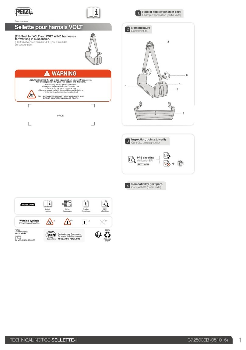
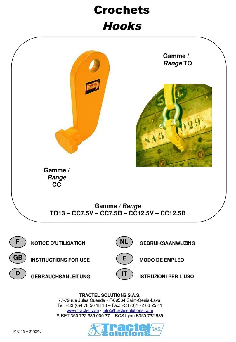
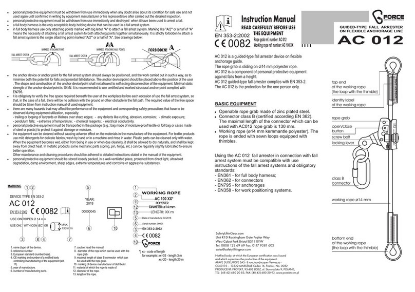
Temporäres Seilsystem Typ HLL und HAL
nach VERORDNUNG (EU) 2016/425,
EN 795:2012 Typ B/C
Temporary rope system type HLL and HAL
according to EN Regulation 2016/425,
EN 795:2012 Type B/C
GBD

2
Temporäres Seilsystem HLL und HALnach
EN Verordnung 2016/425,
EN 795:2012 Typ B/C
Temporary rope system type HLL and HAL acc. to
EN Regulation 2016/425
EN 795:2012 Typ B/C
795:2012 Type B/C
Kaufdatum / date of purchase ______________
Erstbenutzung / rst use __________________
Konformitätserklärung / Conformity: http://ikar-gmbh.de/index.php/de/service/download
nächste Prüfung/
next revision
Handrad prüfen /
check Handwheel
Position/position
Lesbarkeit des Typenschildes prüfen /
check legibility of type plate
Spannfunktion und Funktion des Rastbolzen
prüfen / Check tensioning function and
switching pin
Prüfung vor Inbetriebnahme durchgeführt
+ dokumentiert / Test performed before
commissioning + documented
Datum der Abnahme, Unterschrift Prüfer /
Date of acceptance, signature of checker
Bemerkungen / comments
Grund der Bearbeitung, festgestellte
Mängel / cause of processing, observed
defects
Prüfbuch / Log book
Drehwirbel und Spannanzeiger auf
Funktion prüfen / check swivel and tension
indicator for function
Stahlseil und Seilkausche prüfen /
Check steel rope and rope thimble
Bremseinstellung/
brake adjustment:

3
Dieses Prüfbuch mit Gebrauchsanleitung gehört zum temporären Seilsystem HLL und HAL und muss am
Einsatzort verfügbar sein. Wird das Gerät weiter verkauft, muss diese Gebrauchs- und Montageanleitung in
Landessprache beigefügt sein.
This user manual and the operating instructions are part of the temporary rope system HLL and HAL and
have to be available at the site of operation. In case the device will be resold, the operating instructions
have to be available in the respectively applicable national language.

4
Inhaltsverzeichnis
Directory
Prüfbuch / Log book............................................................................... 2 - 3
DEUTSCH ...............................................................................................6 - 10
ENGLISH................................................................................................ 11 - 15
A
B
C
D
E
F
G
123
Typenschilder Temporäres Seilsystem / Temporary rope system type plates

5
AHersteller · Manufacturer · Fabricante · Fabricants · Costruttore · Fabricante · Fabricant · Fabrikant · Producenta · Fabricantu-
lui · Producent · Tillverkare · Valmistajan osoite ·Produsent · Gyártói · Výrobcu · κατασκευαστής
BÜberwachende Stelle · Monitoring body · Punto de supervisión · Autorité de surveillance · Ente di sorveglianza ·
Pontos a monitorar · Controleorgaan · Jednostka nadzorująca · Unitatea de supraveghere · Tilsynssted · Övervakningsorgan ·
Tarkastuslaitos · Tilsynssted · Felügyeleti szerv · Kontrolné pracovisko · Εποπτική αρχή
C
Produkt · Product · Producto · Produits · Prodotto · Produto · Product · Produkt · Producția · Product · Produkt · Tuote · Produkt ·
Termék · Produkt · προϊόν
Norm · Standard · Norma · Norme · Norma · Norma · Norm · Norma · Norma · Norm · Norm · Standardi · Norm · Norma · Norma ·
Πρότυπη
DHerstelldatum · Date of manufacture · Fecha de fabricatión · Date de fabrication · Data die construzione · Data de fabrico ·
Fabricagedatum · Data produkcji · Data fabricației · Produktionsdato · Tillverkningsdatum · Valmistuspäivä · Produksjonsdato ·
Gyártási dátum · Dátum výroby · Ημερομηνία κατασκευής
E
Seriennummer · Serial number · Número de serie · Numéro de série · Numero di serie · Pontos a monitorar ·
Número de série do aparelho · Seriennummer van het apparaat · Numer seryjny urządzenia · Seria echipamentului ·
Serienummer på grejet · Serienummer · sarjanumero · Serienummer · Sorozatszámot · výrobné číslo · Σειριακός αριθμός
διάταξης
F
Gebrauchsanleitung beachten · read the instruction manual · Prestar atención a las instrucciones de uso · Respecter la
notice d‘utilisation · Rispettare le istruzioni per l‘uso · Observar o manual do utilizador · Houd u aan de gebruiksaanwijzing
· Przestrzegać instrukcji obsługi · Respectați instrucțiunile de utilizare · Iagttag brugsanvisning · Följ bruksanvisningen ·
Käyttöohjetta noudatettava · Overhold bruksanvisning · A használati útmutatóban foglaltak betartandók · Dodržujte návod na
použitie · Προσοχή στις οδηγίες χρήσης
G
Prüfplakette nächste Revision
· next revision test badge · Placa de revisiones de la próxima revisión · Plaquette de contrôle
rochaine révision · Placchetta di prova per la prossima revisione · Placa de ensaio revisão seguinte · Keuringssticker volgende
keuring · Plakietka kontrolna następnej kontroli · Plachetă verificare pentru următoarea inspecție tehnică · Inspektionsmærkat
næste revision · Testplakett nästa kontroll · Seuraavan tarkistuksen tarkastustarra · Kontrollplakett neste revisjon · Vizsgálati
címke a következő felülvizsgálattal · Inšpekčná plaketa budúca revízia · Επόμενος έλεγχος
Typenschild Temporäres Seilsystem / Temporary rope system type plate
DEUTSCH / ENGLISH

6
1. Allgemeine Sicherheitshinweise:
Wichtig: Diese Sicherheitshinweise sind vor der Benutzung dieser persönlichen Schutzausrüstung (PSA) genau zu
studieren und müssen exakt eingehalten werden! Der Benutzer dieser PSA muss die Sicherheitshinweise vor der Ver-
wendung gelesen und verstanden haben und sich strikt an die Herstelleranweisungen halten. Achtung – sonst besteht
Lebensgefahr!
Bei der Kombination von einzelnen Bestandteilen eines Absturzschutzsystems ist darauf zu achten, dass die Funktionen
der einzelnen Elemente uneingeschränkt erhalten bleiben und sich nicht gegenseitig beeinträchtigen. Die mögliche
Absturzhöhe muss stets auf ein Mindestmaß begrenzt werden. Die Gebrauchsanleitungen der Einzelsysteme sind zu
beachten!
Persönliche Schutzausrüstung gegen Absturz darf nur von Personen benutzt werden, die entsprechend ausgebildet
oder sachkundig unterwiesen wurden. Es dürfen keine körperlichen oder gesundheitlichen Beeinträchtigungen vorliegen
(Alkohol-, Drogen-, Medikamenten-, Herz- oder Kreislaufprobleme).
1. Das temporäre horizontale Seilsystem nach EN 795:2012 Typ B/C ist eine geprüfte und zugelassene persönliche
Schutzausrüstung gegen Absturz (PSAgA). In Verbindung mit einem persönlichen Absturzschutzsystem nach EN
363:2008 dient dieses System zur Sicherung von Personen bei Arbeiten in Bereichen mit Absturzgefahr (z.B. auf
Dächern, Gerüsten, oder Schächten). Es gilt zu beachten, dass die Verwendung/Befestigung des Seilsystems nur
an Gerüsten/Konstruktionen erfolgend darf, die dafür vorgesehen und geprüft wurden. Dabei ist der Einuss der
Gerüste/Konstruktionen auf den erforderlichen Freiraum und die Fangstoßkraft zu berücksichtigen. Das temporäre
horizontale Seilsystem nach EN 795:2012 Typ B/C ist nicht für das Heben und Senken von Lasten vorgesehen.
Es ist für die Sicherheit wesentlich, dass das Seilsystem nicht überstiegen wird und die Krafteinleitung im Falle
eines Sturzes durch eine Person 6 kN nicht überschreitet.
2. Das Seilsystem kann im Einsatz nur eine Person schützen, kann jedoch nacheinander von mehreren Personen
genutzt werden. Im Falle eines Sturzes ist ein Hängen der Person von länger als 20 min. auszuschließen (Schock-
gefahr). Auf ausreichenden Freiraum unterhalb des Benutzers ist zu achten. Ein Rettungsplan, in dem alle bei der
Arbeit möglichen Rettungsfälle berücksichtigt sind, muss vor der Benutzung vorhanden sein.
3. Die Seilsysteme dürfen nur in Verbindung mit Verbindungsmitteln mit Bandfalldämpfer nach EN 355 oder
IKAR-Höhensicherungsgeräten nach EN 360 und Auffanggurten nach EN 361:2002, CSA Z259.10-12 oder ANSI/
ASSE Z359.1-2007 als Absturzsicherungssystem benutzt werden. Die Verbindungselemente der verwendeten
Verbindungsmittel/HSG werden direkt mit der Seilanlage verbunden. Ein zusätzlicher Seilgleiter ist nicht erforder-
lich.
4. Bei der Verwendung mit einem Höhensicherungsgerät anderer Hersteller nach EN 360 ist die Eignung dieser
Kombination im kompletten Absturzschutzsystem gemäß den aktuellen Vorschriften durch geeignete Tests nach-
zuweisen, um eine negative Beeinussung des Fangmechanismus (z.B. Dropp-Effekt) auszuschließen.
5. Das Seilsystem ist an ausreichend tragfähigen und den jeweiligen nationalen Vorschriften entsprechenden
Anschlagpunkten mit einer min. Tragfähigkeit von 9 kN (Nordamerika: 22,2 kN) mittels Verbindungselement
(Karabinerhaken) nach EN 362:2004, CSA Z259.12-01, ANSI/ASSE Z359.12-2009
6. Das Absturzschutzsystem sollte möglichst lotrecht (seitliche Auslenkung <30°) über dem Kopf der zu sichernden
Person positioniert werden, damit im Falle eines Sturzes Verletzungen durch pendeln und anprallen an Konstruk-
tionsteilen vermieden wird.
7. Die maximale Spannweite des Seilsystems beträgt 12,0 m
8. Vor jeder Benutzung ist eine Sicht- und Funktionskontrolle einschließlich der Lesbarkeit der Produktkennzeichnung
durchzuführen. Das Gerätegehäuse muss frei von Rissen oder Brüchen sein, der Drehwirbel muss sich einwand-
frei drehen, bei eingeschalteter Rücklaufsperre muss der Seilauslauf blockiert sein. Verbindungselemente dürfen
nicht beschädigt sein und müssen einwandfrei verriegeln. Das Seil muss in seiner gesamten Länge und im vollen
Umfang visuell geprüft werden. Sichtbare Seilverpressungen dürfen nicht verformt oder anderweitig beschädigt
sein.
9. Bei Brüchen, Knicken des Seiles ist das Seilsystem in die Revisionswerkstatt zu gegeben. Das Seil muss dort
ausgetauscht werden. 2
10. Ein beschädigtes und/ oder durch einen Sturz beanspruchtes Seilsystem, sowie bei Zweifel über den sicheren
Zustand des Gerätes, ist dieses sofort dem Gebrauch zu entziehen. Es darf erst nach schriftlicher Freigabe durch
eine vom Hersteller autorisierten und sachkundigen Person oder vom Hersteller weiterverwendet werden. 1
DEUTSCH

7
11. Reparaturen dürfen nur vom Hersteller oder vom Hersteller geschulten und autorisierten Personen durchgeführt
werden.
12. Die Lebensdauer des Seilsystems beträgt je nach Beanspruchung ca. 10 Jahr und muss bei der jährlichen Prüfung
bestimmt werden.
13. Je nach Beanspruchung, mindestens alle zwölf Monate muss das Seilsystem vom Hersteller oder vom Hersteller
geschulten und autorisierten Person überprüft werden. Die Wirksamkeit und Haltbarkeit des temporären Seilsys-
tems hängt von der regelmäßigen Prüfung ab.
14. Das Seilsystem darf in einem Temperaturbereich von -30°C (-22°F) bis +55°C (+131°F) eingesetzt werden. 3
15. Das Seilsystem, sowie seine die gesamte persönliche Schutzausrüstung gegen Absturz sind vor den Einwirkungen
von Schweißammen und -funken, Feuer, Säuren, Laugen und ähnlichem zu schützen.
16. Es dürfen keine Veränderungen an den Komponenten des Seilsystems vorgenommen werden
17. In Deutschland müssen die DGUV R 112-198 und die DGUV R 112-199, sowie die DGUV Information 212-870 be-
achtet werden. Das temporäre Seilsicherungssystem erfüllt zusätzlich die berufsgenossenschaftlichen Prüfgrund-
sätze GS-PS-11:2018 für den Holzbau.
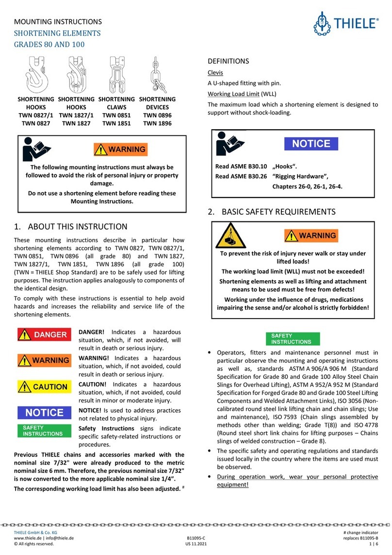
Aufbau des Seilsystems:
1. Das Seil des Shockabsorbers HLL ist vor der Montage bis zur Markierung aus dem Shockabsorber heraus zu
ziehen. Dazu die Rücklaufsperre auf Position 1 drücken. Die Rücklaufsperre ist nach dem Vorgang zurück in
Position 2 zu drücken.
2. Das Seilsystem wird wie in der Abbildung auf Seite 7 montiert.
3. Das Seilsystem HLL wird durch Drehen am Handrad vorgespannt. Der Indikator am Wirbel des Shockabsorbers
hat eine blaue (1,0 kN) und eine rote (Vorspannung zu hoch) Markierung. Das Seilsystem ist richtig vorgespannt,
wenn am Indikator die blaue Markierung sichtbar ist.
HLL EN 795:2012 Typ B/C
DEUTSCH

8
Schalt-Stellung Position 1
Freilauf (Abseilen)
Schalt-Stellung Position 2
Rücklaufsperre (Spannen)
HAL EN 795:2012 Typ B/C
HLL 12/8 ANSI/ASSE Z359.0-2007
Hinweis: Das Seilsystem HLL 12/8 wird durch Drehen am Handrad vorgespannt. Der Indikator am Wirbel des Shock-
absorbers hat eine gelbe (1,5 kN) und eine grüne (1,8 kN) Markierung. Das Seilsystem ist richtig vorgespannt, wenn der
Indikator zwischen der gelben und der grünen Markierung steht.
1,5 kN - 1,8 kN
DEUTSCH

9
Hinweis: Im Falle einer Abseilung oder im Rettungsfall sind während der Absenkung geeignete Schutzhandschuhe zu
tragen.
1. Das Handrad ist Richtung Spannen zu drehen um die Rücklaufsperre zu entlasten.
2. Das Handrad festhalten und die Rücklaufsperre in Position 1 schalten.
3. Beide Hände werden ans Handrad gelegt. Der Druck der Hände wird reduziert bis das Handrad langsam
durch die Hände rutscht, der Absenkvorgang wird somit eingeleitet.
4. Der Absenkvorgang wird durch den Druck der Hände am Handrad kontrolliert. Das Handrad keinesfalls los
lassen! Es stehen maximal 2,0 m (HLL) und maximal 1 m (HLL12/8) Rettungslänge zur Verfügung!
Pege und Wartung:
Achtung unbedingt beachten: Die Aufbewahrung und der Transport der Höhensicherungsgeräte müssen trocken,
staub- und ölfrei erfolgen!
1. Bei Geräten, die ständig der Witterung ausgesetzt sind, sollte das Stahlseil in regelmäßigen Abstanden mit säure-
freiem Öl oder Vaseline leicht eingefettet werden.
2. Textile Verbindungsmittel aus PES / Dyneema dürfen nur mit warmen Wasser und neutralen Reinigungsmitteln
gereinigt werden. Reste des Reinigungsmittels sind rückstandslos mit klarem Wasser auszuspülen.
3. Die Trocknung von nassen textilen Verbindungsmitteln darf nur auf natürliche Weise erfolgen. Auf keinen Fall in
der Nähe von Hitzequellen, Feuer o.ä. trocknen.
Systemaufbau nach berufsgenossenschaftlichem Prüfgrundsatz GS-PS-11:2018 mit Höhen-
sicherungsgerät Typ HWB 1,8
DEUTSCH

10
Übersicht der Bedienelemente
A
B
C
D
E
F
A
Drehwirbel
· Swivel eye ·
B
Handrad
· Handwheel · Volante · Volant · Manopola · Volante de manobra · Handlier · pokrętło · Roată manuală · Håndhjul ·
Handhjul · Käsipyörä · Håndhjul · Kézikerék · Ručné koliesko · Περιστρεφόμενος χειρομοχλός
C
Klappgriff · folding handle
D
Vorspannungsmarkierungen · Force marks
E
Schaltbolzen Rücklaufsperre · Switching pin · Perno de conmutación · Goujon de commutation · Perno di attivazione · Pino
de comutação · Bloqueio de retorno · Borgbouten Teruglooprem · trzpień przełączający blokada cofania · Bolț de cuplare
Dispozitiv de blocare · Skiftestang Tilbageløbsspærreanordning · Omställningstapp rekylspärr · Kytkentäpultti Taljapyörä ·
Forbindelsesbolt · Tilbakeløpssperreinnretning · Kapcsolócsap Visszafutási zár · Prepínací čap Blokovanie spätného chodu ·
Πείρος επιλογής Φραγή επιστροφής σχοινιούδιάταξης
FSeilkausche · rope thimble
DDetails / Markierungen der Seilvorspannung am Kraftabsorber
Vorspannungsindikator (USA):
Gelb = 1,5 kN
Grün = 1,8 kN
Vorspannungsindikator (EUROPA):
Blau = 1 kN
Rot = zu hohe Vorspannung
DEUTSCH

11
1. General safety instructions:
IMPORTANT: These safety instructions must be studied carefully before using this personal protective equipment (PPE)
and must be complied with in every respect! The user of this PPE must have read and understood the safety instructions
before use and must strictly adhere to the manufacturer's instructions. Caution – failure to do so may result in danger of
death!
Where individual components of a fall protection system are combined, it must be ensured that the functionality of each
individual component is retained without restriction and that the components do not obstruct each other. The potential
fall height must always be kept to a minimum. The instruction manuals for the individual systems must be observed at all
times!
Personal protective equipment against falls from a height may only be used by appropriately trained persons or persons
who have been instructed by an expert. The person must have no physical or health-related impediments (alcohol-relat-
ed, narcotics-related, medicine-related or circulation problems).
1. The temporary horizontal rope system in accordance with EN 795:2012 Type B/C has been tested and approved
as personal protective equipment (PPE) against falling from a height. When used in conjunction with a personal fall
protection system in accordance with EN 363:2008, this system protects people working in areas where there is a
risk of falling (e.g. on roofs, scaffolding or shafts). It should be noted that the rope system may only be used/xed
on scaffolding/constructions that have been designed and tested for this purpose. The inuence of the scaffolding/
constructions on the required clearance and the impact force must be taken into account. The temporary horizontal
rope system in accordance with EN 795:2012 Type B/C is not intended for lifting and lowering loads.
2. For safety reasons, it is important not to step on the rope system is and that the force applied does not exceed 6
kN in the event a person falls.
3. The rope system can only be used to secure one person at a time, but may be used by multiple persons consecu-
tively. In the event of a fall, it must be ensured that the affected person is not left suspended for longer than 15 min.
(shock hazard). Make sure there is enough clearance beneath the user. A rescue plan that takes into account all
potential cases of rescue in work-related scenarios must be in place before use.
4. The rope systems may only be used as fall arrest systems in conjunction with lanyards with tear web energy
absorbers compliant with EN 355 or fall arrest devices compliant with EN 360 and safety harnesses compliant with
EN 361:2002, CSA Z259.10-12 or ANSI/ASSE Z359.1-2007. The connection elements of the lanyard/fall arresting
device used are connected directly to the rope system. There is no need for an additional rope slider.
5. The rope system must be secured to sufciently load-bearing fastening points with a minimum load-bearing
capacity of 9 kN (North America: 22.2 kN) by means of a connection element (snap hook) in accordance with
EN 362:2004, CSA Z259.12-01, ANSI/ASSE Z359.12-2009.
6. When used with a fall arresting device in accordance with EN 360, the suitability of this combination in the com-
plete system must be demonstrated by suitable tests in accordance with current regulations.
7. The system should be positioned as vertically as possible (lateral deection <30°) above the head of the person
to be secured in order to keep any swinging to a minimum during the fall arrest process. To avoid injuries caused
by swinging and hitting structural parts in the event of a fall, the fall protection system should be positioned as
vertically as possible (lateral deection <30°) above the head of the secured person.The maximum span of the
rope system is 12.0m
8. Before each use, it is important to carry out a visual and functional check and to ensure that the product labelling
is legible. The device housing must have no cracks or fractures, the swivel must rotate properly, the rope must
stop moving as soon as the backstop is activated. The connecting elements must not be damaged and must lock
properly. The entire length and full extent of the rope must be visually inspected. Visible rope compressions must
not be deformed or otherwise damaged.
9. If the rope breaks or buckles, the rope system must be handed over to the inspection workshop. The webbing or
rope must be replaced there. 2
10. If a rope system is damaged and/or strained by a fall, or if you have doubts about the safety of the device, stop
using it immediately. It may only be reused following written approval by a competent person authorised by the
manufacturer or by the manufacturer itself. 1
ENGLISH

12
11. Repairs may only be carried out by the manufacturer or by persons trained and authorised by the manufacturer.
12. The service life of the rope system is approx. ten years, depending on the applied loads, and must be veried
during the annual inspection.
13. Depending on the applied load, but at least once every twelve months, the rope system must be checked by
the manufacturer or persons who have been trained and authorised by the manufacturer. The effectiveness and
durability of the rope system depend on regular inspections.
14. The rope system may be used in a temperature range of -30°C (-22°F) to +55°C (+131°F). 3
15. The rope system and all its personal fall protection equipment must be protected from the effects of welding
ames/sparks, re, acids, alkalis and the like.
16. It is not permitted to modify any of the components of the rope system
17. DGUV R 112-198, DGUV R 112-199 and DGUV information 212-870 apply in Germany and must be observed.
130/5000. The temporary lifeline system also meets the Professional Association test principles GS-PS-11: 2018
for timber construction.
Rope system design:
1. Before installation, pull the shock absorber rope out of the shock absorber right up to the mark. To do so, push the
backstop to position 1. After the process, push the backstop back to position 2.
2. The rope system is mounted as shown in the gure below.
3. The rope system is pre-tensioned by turning the handwheel. The indicator next to the eyelet of the shock absorber
has a yellow (1.5 kN) and a green (1.8 kN) mark. The rope system is correctly pre-tensioned when the green mark
is visible on the indicator.
HLL EN 795:2012 Type B/C
Anchorage device
9 kN
Shock absorber
Anchorage device
9 kN
ENGLISH

13
Connector
EN 362
Anchorage device
9 kN
Anchorage device
9 kN
Switching position 1
Freewheel (abseiling)
Switching position 2
Backstop (clamp)
HAL EN 795:2012 Typ B/C
HLL 12/8 ANSI/ASSE Z359.0-2007
Note: The cable system HLL 12/8 is pre-tensioned by turning the handwheel. The indicator on the swivel eye of the
shock absorber has a yellow (1.5 kN) and a green (1.8 kN) mark. The cable system is properly tensioned when the
indicator is between the yellow and green markings located.
Connector
CSA Z259.12-01,
ANSI/ASSE Z359.12-2009
1,5 kN - 1,8 kN
Connector
CSA Z259.12-01,
ANSI/ASSE Z359.12-2009 Anchorage device
North America
22,2 kN
Anchorage device
North America
22,2 kN
Shock absorber
ENGLISH

14
Please note: In the case of abseiling or rescue operations, suitable protective gloves must be worn when descending.
1. The hand wheel must be turned in the clamping direction to release the backstop
2. Hold the hand wheel rmly and move the backstop to position 1.
3. Both hands must be placed on the hand wheel. The applied hand pressure is reduced until the hand wheel
slides slowly through the hands, thus initiating the lowering process.
4. The lowering process is controlled by the pressure of the hands on the hand wheel. Do not let go of the hand
wheel for any reason! There is a maximum of 2.0 m (HLL) and a maximum of 1 m (HLL12/8) rescue
length available!
Maintenance and care:
Attention, this must always be observed: The fall arresters must be kept dry and away from dust and oil during storage
and transport!
1. If the equipment is constantly exposed to the weather, the steel rope should be greased with acid-free oil or
Vaseline at regular intervals.
2. Textile lanyards made of PES / Dyneema may only be cleaned with warm water and neutral cleaning solutions.
Rinse off any cleaning agent residues completely with clean water.
3. Wet textile lanyards must be left to dry naturally. Do not, under any circumstance, attempt to dry them next to
sources of heat, re or the like.
ENGLISH

15
Overview of the controls
A
B
C
D
E
F
A
Drehwirbel
· Swivel eye ·
B
Handrad
· Handwheel · Volante · Volant · Manopola · Volante de manobra · Handlier · pokrętło · Roată manuală · Håndhjul ·
Handhjul · Käsipyörä · Håndhjul · Kézikerék · Ručné koliesko · Περιστρεφόμενος χειρομοχλός
C
Klappgriff · Folding handle
D
Vorspannungsmarkierungen · Force marks
E
Schaltbolzen Rücklaufsperre · Switching pin · Perno de conmutación · Goujon de commutation · Perno di attivazione · Pino
de comutação · Bloqueio de retorno · Borgbouten Teruglooprem · trzpień przełączający blokada cofania · Bolț de cuplare
Dispozitiv de blocare · Skiftestang Tilbageløbsspærreanordning · Omställningstapp rekylspärr · Kytkentäpultti Taljapyörä ·
Forbindelsesbolt · Tilbakeløpssperreinnretning · Kapcsolócsap Visszafutási zár · Prepínací čap Blokovanie spätného chodu ·
Πείρος επιλογής Φραγή επιστροφής σχοινιούδιάταξης
FSeilkausche · Rope thimble
DDetails / rope pre-tension marks on the shock absorber
Pre-tension indicator (USA):
Yellow = 1.5 kN
Green = 1.8 kN
Pre-tension indicator (EUROPE):
Blue = 1 kN
Red = pre-tension too high
ENGLISH

16
Baumusterprüfende Stelle/
Engaged body:
DEKRA Testing and Certication GmbH
Dinnendahlstr. 9;
D-44809 Bochum / Germany
CE0158
Überwachung durch/
controlled and autited by:
DGUV Test
Prüf- und Zertizierungsstelle
des FA PSA
D-42781 Haan / GERMANY
CE0299
Hersteller / Manufacturer:
IKAR GmbH
Nobelstr. 2
36041 Fulda
GERMANY
Tel.: +49 (0)661 22050
www.ikar-gmbh.de
Prüfbuch_Temporäres Seilsystem_V2_20190607
This manual suits for next models
1
Table of contents
Languages:
Other IKAR Safety Equipment manuals

IKAR
IKAR HRA Series User manual
IKAR
IKAR HWB 1.8 Product guide
IKAR
IKAR ABS 5 B Product guide

IKAR
IKAR ASS-1 Product guide
IKAR
IKAR HWB 2,8 DW Product guide

IKAR
IKAR HWB 1.8 Product guide
IKAR
IKAR ANCHORAGE SLINGS User manual

IKAR
IKAR HRA Series User manual
IKAR
IKAR AASS-M Product guide

IKAR
IKAR HAS 9 Product guide
Popular Safety Equipment manuals by other brands
MSA
MSA SingleLine SCOUT operating manual
BARRON
BARRON Exitronix LED-90 Series installation instructions

Tractel
Tractel travsafe PA Installation, operating and maintenance manual
NEW TRIBE
NEW TRIBE NIKOSI SADDLE manual

Vac - Alert
Vac - Alert VA-2000 installation instructions

Petzl
Petzl FLY TECHNICAL NOTICE
