Thiele TWN 0827/1 User manual

MOUNTING INSTRUCTIONS
SHORTENING ELEMENTS
GRADES 80 AND 100
THIELE GmbH & Co. KG # change indicator
© All rights reserved. US 11.2021 1 | 6
SHORTENING
HOOKS
TWN 0827/1
TWN 0827
SHORTENING
HOOKS
TWN 1827/1
TWN 1827
SHORTENING
CLAWS
TWN 0851
TWN 1851
SHORTENING
DEVICES
TWN 0896
TWN 1896
The follo ing mounting instructions must al ays be
follo ed to avoid the risk of personal injury or property
damage.
Do not use a shortening element before reading these
Mounting Instructions.
1. ABOUT THIS INSTRUCTION
These mounting instructions describe in particular ho
shortening elements according to TWN 0827, TWN 0827/1,
TWN 0851, TWN 0896 (all grade 80) and TWN 1827,
TWN 1827/1, TWN 1851, TWN 1896 (all grade 100)
(TWN = THIELE Shop Standard) are to be safely used for lifting
purposes. The instruction applies analogously to components of
the identical design.
To comply ith these instructions is essential to help avoid
hazards and increases the reliability and service life of the
shortening elements.
DANGER! Indicates a hazardous
situation, hich, if not avoided, ill
result in death or serious injury.
WARNING! Indicates a hazardous
situation, hich, if not avoided, could
result in death or serious injury.
CAUTION! Indicates a hazardous
situation, hich, if not avoided, could
result in minor or moderate injury.
NOTICE! Is used to address practices
not related to physical injury.
Safety Instructions signs indicate
specific safety-related instructions or
procedures.
Previous THIELE chains and accessories marked ith the
nominal size 7/32" ere already produced to the metric
nominal size 6 mm. Therefore, the previous nominal size 7/32"
is no converted to the more applicable nominal size 1/4”.
The corresponding orking load limit has also been adjusted.
#
DEFINITIONS
Clevis
A U-shaped fitting ith pin.
Working Load Limit (WLL)
The maximum load hich a shortening element is designed to
support ithout shock-loading.
Read ASME B30.10 „Hooks“.
Read ASME B30.26 “Rigging Hard are”,
Chapters 26-0, 26-1, 26-4.
2. BASIC SAFETY REQUIREMENTS
To prevent the risk of injury never alk or stay under
lifted loads!
The orking load limit (WLL) must not be exceeded!
Shortening elements as ell as lifting and attachment
means to be used must be free from defects!
Working under the influence of drugs, medications
impairing the sense and/or alcohol is strictly forbidden!
•Operators, fitters and maintenance personnel must in
particular observe the mounting and operating instructions
as ell as, standards ASTM A 906/A 906 M (Standard
Specification for Grade 80 and Grade 100 Alloy Steel Chain
Slings for Overhead Lifting), ASTM A 952/A 952 M (Standard
Specification for Forged Grade 80 and Grade 100 Steel Lifting
Components and Welded Attachment Links), ISO 3056 (Non-
calibrated round steel link lifting chain and chain slings; Use
and maintenance), ISO 7593 (Chain slings assembled by
methods other than elding; Grade T(8)) and ISO 4778
(Round steel short link chains for lifting purposes – Chains
slings of elded construction – Grade 8).
•The specific safety and operating regulations and standards
issued locally in the country here the items are used must
be observed.
•During operation ork, ear your personal protective
equipment!

MOUNTING INSTRUCTIONS
SHORTENING ELEMENTS
GRADES 80 AND 100
THIELE GmbH & Co. KG # change indicator
© All rights reserved. US 11.2021 2 | 6
•The directions given in these mounting instructions and
specified documentations relating to safety, assembly,
operation, inspection, and maintenance must be made
available to persons operating and using the shortening
elements.
•These mounting instructions must be available in a place
near the product during the time the equipment is used.
Please contact the manufacturer if replacements are
needed. Also see chapter 11.
•Improper assembly and use may cause personal injury
and/or damage to property.
•Assembly and removal as ell as inspections and
maintenance must exclusively be carried out by skilled,
qualified, trained and authorized persons only.
•Structural changes are impermissible (e.g. elding, bending).
•Operators must carry out a visual inspection and, if
necessary, a functional test of the safety equipment before
each use.
•Never use orn-out, bent or damaged shortening elements.
•Only lift loads that do not exceed the orking load limit of
the corresponding sling chain assembly.
•Never expose shortening elements to loads exceeding the
specified orking load limit.
•When using shortening elements ithout additional safety
elements (e.g. TWN 0827, TWN 1827, TWN 0851 or
TWN 1851), special care must be taken and the correct
position of the chain in the shortening element is to be
verified for each individual lifting operation.
•Shortening hooks must not be attached directly to loads, e.g.
metal sheets.
•Only chain legs and shortening elements of the same
nominal size and grade may be connected.
•No one including you (operator) must be in the ay of the
moving load (hazard area).
•Safety elements must not be excessively stressed or strained
operationally.
•Do not use force hen mounting/positioning the shortening
elements.
•Do not t ist or knot the chains together.
•In case of multi-leg sling chain assemblies never allo for
sling angles of less than 30 ° and in excess of 75 °.
•Avoid bending loads to act on chain links and shortening
elements.
•Make sure to use shortening/grab hooks or cla s for chain
shortening purposes.
•In case of shortening cla s only put loads on the chain
exiting the cla pocket bottom.
•During lifting your hands or other body parts must not come
into contact ith lifting means. Only remove lifting means
manually (use your hands).
•Avoid impacts, e.g. due to abruptly lifting loads ith chain in
slack condition.
•Usage ithout orking safety elements (cotter pins, do el
pins) is not permissible.
•Shortening elements must be allo ed to move freely in all
tensile directions.
•In the event of doubts or concerns about the proper and safe
use, inspection, maintenance or similar things contact your
safety officer or the manufacturer.
THIELE is not responsible for damage caused by
non-observance of the instructions, rules, standards and notes
indicated!
As regard grade 100, THIELE does not give its approval to the
assembly of components sourced from different
manufacturers!
As a rule, shortening elements and chain slings are not
permitted for the transportation of persons.
3. DESCRIPTION AND INTENDED USE
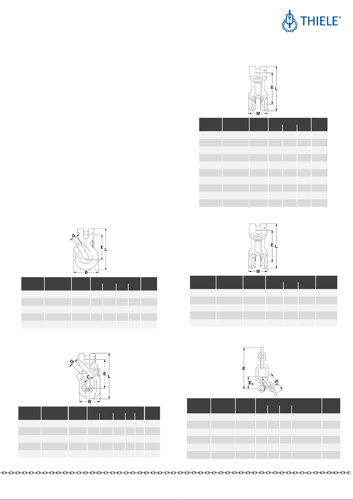
THIELE shortening elements (shortening hooks, shortening
cla s, shortening devices) are exclusively intented to shorten
individual chain legs ithin several sling chain assemblies
according to ASTM A 906/A 906M.
Shortening elements must only be used ithin a single loaded
chain leg.
Shortening elements must exclusively be used
•
ithin the limits of their permissible orking load limit,
•
for permissible attachment methods and sling angles,
•
ithin the temperature limits prescribed,
•
by trained and authorized persons.
THIELE shortening elements meet the
EG Machinery Directive 2006/42/EG requirements and feature
a safety factor of at least 4 based on orking load limit.
The shortening elements are designed to ithstand 20 000
dynamic load changes under maximum load conditions. In the
event of higher loads (e.g. multi-shift/automatic operation), the
orking load limit must be reduced.
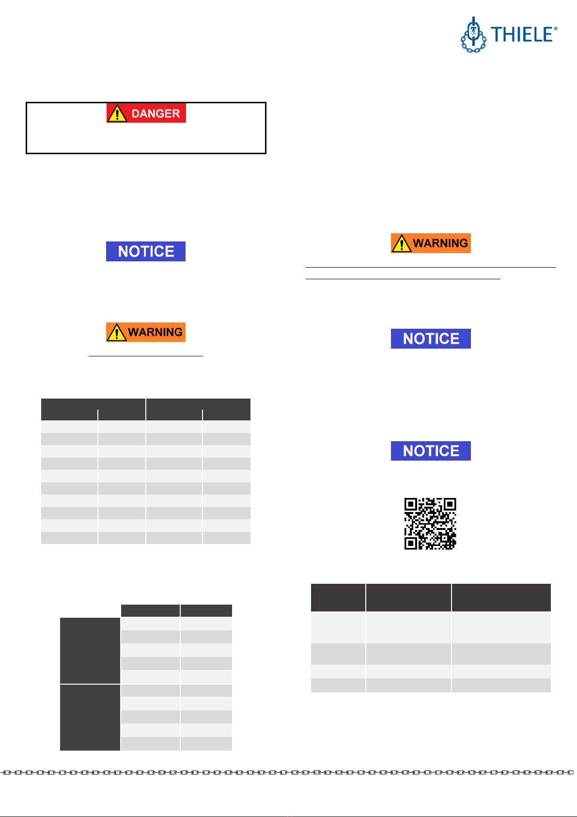
Shortening elements are marked ith nominal chain size and
quality grade, manufacturer’s symbol and traceability code.
Shortening hooks ith safety device can also be used ithin
lashing chain assemblies. When used ithin a lashing system,
the maximum lashing capacity (LC) is obtained by doubling the
orking load limit.
Any alternating use for lifting and lashing purposes is
impermissible!

MOUNTING INSTRUCTIONS
SHORTENING ELEMENTS
GRADES 80 AND 100
THIELE GmbH & Co. KG # change indicator
© All rights reserved. US 11.2021 3 | 6
4. COMMISSIONING
Prior to using the components for the first time assure that
•the components comply ith the order and have not been
damaged,
•test certificates and mounting instructions are at hand,
•markings correspond ith hat is specified in the
documentation,
•inspection deadlines and the qualified persons for
examinations are determined,
•visibility and functional testings are carried out and
documented,
•documentation is safely kept in an orderly manner.
Dispose of the packing in an environmentally compatible ay
according to local rule.
5. TECHNICAL DATA
Tables include only article numbers of standard and not
customized parts.
5.1 Shortening hooks TWN 082 /1, Grade 80
Execution TWN 0827 ithout safety pin
Nominal
size Article no.
WLL
[lbs]
Dimensions [mm] Mass
E G L B [lbs]
5/16 F33201 4 500 61 9 101
61 1.19
3/8 F33211 7 100 73 12 125
75 2.18
1/2 F33221 12 000
95 15 160
95 4.80
5/8 F33231 18 100
112
18 188
120
7.60
3/4 F33246 28 300
148
22,5
242
141
16.20
5.2 Shortening hooks TWN 182 /1, Grade 100
Execution TWN 1827 ithout safety pin
Nominal
size Article no.
WLL
[lbs]
Dimensions [mm] Mass
E G L B C [lbs]
1/4
# 1)
F33195 3 100 - - - - - -
5/16 F33205 5 700 71 9.5 110
55
34
1.12
3/8 F33215 8 800 83 12.5
132
67
42
2.09
1/2 F33225 15 000
109
15.5
168
79
54
3.80
5/8 F33235 22 600
137
18.5
208
91
66
8.05
1) in progress
5.3 Shortening claws TWN 0851, Grade 80
Nominal
size Article no.
WLL
[lbs.]
Dimensions [mm]
Mass
E L M [lbs.]
1/4
#
F34910 2 500 54 81 32 0.46
9/32 F34920 3 500 74 108 43 0.93
5/16 F34925 4 500 80 115 46 1.23
3/8 F34930 7 100 90 134 56 2.07
1/2 F34940 12 000
117 175 72 4.63
5/8 F34950 18 100
144 214 86 7.94
3/4 F34970 28 300
158 241 98 11.90
7/8 F34980 34 200
198 295 118 19.84
1 F34985 47 700
195 309 130 26.45
1-¼ F34990 72 300
240 381 160 41.88
5.4 Shortening claws TWN 1851, Grade 100
Nominal
size
Article
no.
WLL
[lbs]
Dimensions [mm] Mass
E L M [lbs]
1/4
#
F34904 3 100 54 81 32 0.46
5/16 F34924 5 700 80 115 46 1.32
3/8 F34934 8 800 90 134 56 2.12
1/2 F34944 15 000 117 175 72 4.63
5/8 F34954 22 600 144 214 86 7.94
5.5 Shortening devices TWN 0896, Grade 80
Nominal
size Article no.
WLL
[lbs]
Dimensions [mm] Mass
E E
1
E
2
Interm. Link
[lbs]
1/4
#
F0896068
2 500 137
31 60 Ø10x46x23
0.71
5/16 F0896088
4 500 176
38 78 Ø13x60x30
1.54
3/8 F0896108
7 100 215
46 99 Ø16x70x35
3.09
1/2 F0896138
12 000
270
59 126
Ø18x85x40
5.73
5/8 F0896168
18 100
326
76 150
Ø22x100x50
9.92
7/8 F0896228
34 200
450
100
210
Ø32x140x70
26.46

MOUNTING INSTRUCTIONS
SHORTENING ELEMENTS
GRADES 80 AND 100
THIELE GmbH & Co. KG # change indicator
© All rights reserved. US 11.2021 4 | 6
5.6 Shortening devices TWN 1896, Grade 100
Nominal
size Article no.
WLL
[lbs]
Dimensions [mm] Mass
[lbs]
E E
1
E
2
Interm. Link
1/4
#
F189606 3 100 137
31
60 Ø10x46x23 0.71
5/16 F189608 5 700 175
38
78 Ø13x60x30 1.54
3/8 F189610 8 800 215
46
99 Ø16x70x35 3.09
1/2 F189613 15 000
270
59
126
Ø18x85x40 5.73
5/8 F189616 22 600
326
76
150
Ø22x100x50
11.02
6. REMOVAL
6.1 Preparations
All components to be installed or used must be in perfect
condition and the relevant orking load limits of all parts must
accommodate the respective load to be handled.
6.2 Clevis fastening system
The clevis fastening system only
permits attachment of the nominal
chain size that suits the attachment
component.
6.2.1 ASSEMBLY
•
If necessary, remove do el pin and
pin.
•
(A) Place end of chain leg bet een
the lateral clevis elements.
•
(B) Push pin from the side fully
into the clevis and through the
last chain link of the leg.
•
(C) Drive do el pin fully in (must
not project) to secure the pin. The
slot must face a ay from the pin.
Check hether the chain runs smoothly!
The do el pins must only be installed once.
Only connect pins and attachment components of identical
grades. Starting ith Ø ½” the pins are marked on the front
end.
6.2.2 DISASSEMBLY
•
Slacken the respective chain.
•
(A) Drive do el pin out using
hammer and drift punch
1)
.
•
(B) Push pin out using a drift
punch.
•
(C) Remove the chain.
1) Suitable drift punches are available by Article No. Z03303.
6.3 Shortening device
One of the short chain legs has to be connected
to the master link, may by a ring shackle as part
of a fixed size master link assembly or by a
connector.
The second short chain leg has to be connected
to a shortening cla or shortening hook ith
clevis-type fastening system.
A longer chain leg ith a hook or other device
at its end to carry the load has to be mounted
to the ringshackle. This chain leg can be
shortened by the usage of the mounted
shortening cla or shortening hook.
7. CONDITIONS OF USE
.1 Normal use
A shortening element is only used to shorten a single chain leg
and never to transfer the load to additional chain legs. The
shortened part of the chain leg must remain unloaded.
Therefore, it is not allo ed to create a 4-leg chain sling assembly
made of a 2-leg chain sling assembly by adding shortening
devices.
Shortening individual chain legs is indicative of a non-
symmetrical load distribution. In this case, attention is to be paid
to orking load limit reductions.
.2 Shortening hooks
Assembly and disassembly are only carried out in unloaded
condition.
7.2.1 ASSEMBLY
Push the chain link of the chain leg to be shortened past the
hook tip into the slot. If a safety bolt is present, push it back ith
the chain or pull it back by hand at the rear edge nut. Make sure
that the lo er leg of the chain link inserted into the slot is
positioned near the bottom of the hook and, if present, that the
safety pin above the upper leg of this chain link returns
automatically to its extended safety position.
The chain leg to be loaded can be located either to the right or
left of the central longitudinal plane of the hook.

MOUNTING INSTRUCTIONS
SHORTENING ELEMENTS
GRADES 80 AND 100
THIELE GmbH & Co. KG # change indicator
© All rights reserved. US 11.2021 5 | 6
7.2.2 DISASSEMBLY
If present, pull back the locking pin on the rear knurled nut and
lift the shortened chain leg completely out of the slot of the
shortening hook to remove it.
.3 Shortening claws
Assembly and disassembly are only carried out in un-loaded
condition.
7.3.1 ASSEMBLY
Push the piece of chain selected for shortening the chain leg to
be shortened into the pocket of the shortening cla . Make sure
that the lo er curve lies firmly in the bottom of the pocket. The
chain leg area to be loaded ith the component located thereon
for attachment to the load (e.g. hook) extends do n ards hen
the chain is correctly inserted.
Check the correct positioning of the chain link in the pocket for
each individual lifting operation!
7.3.2 DISASSEMBLY
Move the chain link in the cla completely out of the cla
pocket by lifting the afore loaded chain leg and pulling it a ay
from the shortening cla . If necessary, carry out a supporting
tilting movement of the shortening cla .
.4 Influence of temperature
The respective temperature range limits must be considered for
all components used.
Using shortening elements in high temperatures ill cause the
orking load limit to be reduced as indicated belo .
Temperature range Remaining WLL
Grade 80
-40 °C ≤ t ≤ 205 °C
-40 °F ≤ t ≤ 400 °F 100 %
205 °C < t ≤ 300 °C
400 °F < t ≤ 572 °F 90 %
300 °C < t ≤ 400 °C
572 °F < t ≤ 752 °F 75 %
Grade 100 -30 °C ≤ t ≤ 205 °C
-22 °F ≤ t ≤ 400 °F 100 %
If the shortening elements have been exposed to
temperatures exceeding the maximum values specified,
they must not be used furthermore.
.5 Environmental influence
Sling chain assemblies must not be used in environments here
acids, aggressive or corrosive chemicals or their fumes are
present. Hot-dip galvanizing or an electro galvanic treatment is
prohibited as ell. Shortening elements are not intended to be
used for abrasive blasting environments.
8. INSPECTION, MAINTENANCE, DISPOSAL
8.1 General
Inspections and maintenance must be arranged by the O ner!
Inspection intervals must be determined by the O ner!
Visual inspections must be regularly carried out and
documented by competent and trained persons, at least once a
year or more frequently if the shortening elements are in heavy
duty service. After three years at the latest they must
additionally be examined for cracks. A load test is not a
substitute for this examination.
The results of the inspection shall be kept in a file that has to be
set up for each sling chain before first use. The register shall
sho characteristic data of the chains and components as ell
as identity details.
Immediately stop using shortening elements that sho the
follo ing defects:
•missing or illegible identification/marking
•deformation, elongation or fractures of chains or
components
•cuts, notches, cracks, incipient cracks, pinching
•links heated beyond permissible limit
•severe corrosion
•reduction of the averaged pin diameter by more than 10 %
as mean value of measurements taken perpendicularly
to ards each other
•impaired or missing safety systems
•missing or damaged do el pins.
Cleaning (e.g. prior to inspections) must not take place by using
flames or methods that might cause hydrogen embrittlement
(e.g. pickling or immersion in acidic solutions).
8.2 Inspection service
THIELE offers inspection maintenance and repair services by
trained and competent personnel. Please contact us for further
information.

MOUNTING INSTRUCTIONS
SHORTENING ELEMENTS
GRADES 80 AND 100
THIELE GmbH & Co. KG # change indicator
© All rights reserved. US 11.2021 6 | 6
8.3 Maintenance and repair
Maintenance and repair ork must only be performed
by competent and trained persons.
Minor notches and cracks may be eliminated by careful grinding
observing the maximum cross section reduction requirement of
max. 10 % and avoid making more severe cuts or scores.
All maintenance and repair activities must be documented
properly.
8.4 Disposal
All steel components and accessories taken out of service must
be scrapped in accordance ith local regulations and provisions.
9. SPARE PARTS
Use only original spare parts.
9.1 Spares parts sets for clevis fastening system
Sets consists of pin and do el pin.
Grade 80 Grade 100
Nominal size Article no. Nominal size Article no.
1/4
#
F48694 1/4
#
F48686
9/32 F48352 5/16 F48687
5/16 F48352 3/8 F48688
3/8 F48355 1/2 F48689
1/2 F48358 5/8 F48690
5/8 F48361
3/4 F48369
7/8 F48367
1 F48373
1-¼ F48371
9.2 Spare parts sets for safety elements
TWN 082 /1 and TWN 182 /1
Consisting of safety pin spring and knurled scre .
Nominal size Article no.
TWN 0827/1
Grade 80
5/16 F48330
3/8 F48328
1/2 F48329
5/8 F48339
3/4 F48345
TWN 1827/1
Grade 100
1/4
#
F483310
5/16 F48330
3/8 F48328
1/2 F483290
5/8 F48339
9.3 Disassembly
Remove the safety parts by cutting of the knurled scre .
After ards remove spring and safety pin.
9.4 Assembly
Before orking on ne assembly please clean the hole and
crease it slightly.
First put in the spring, after ards take the safety pin ith its thin
end into the spring and push it until the thread is sho n on the
other side of the hook body.
Check pin and spring can move easily.
Then assemble knurled scre and secure it by three punch
marks on the thread against unintended opening.
Check the system again.
10. STORAGE
Shortening elements must be stored properly sorted and in dry
conditions at temperatures bet een 32 °F and 104 °F.
Do not store in a manner that causes mechanical damage.
11. THIELE OPERATING AND MOUNTING
INSTRUCTIONS
Current mounting and operating instructions are available as a
PDF do nload on the THIELE- ebsite .thiele.de.
12. PUBLISHING INFORMATION
#
Company KWS Inc. THIELE GmbH & Co. KG
(Distributor) (Manufacturer)
Postal
address
P.O. Box 470487
Tulsa, OK 74147
USA
Werkstrasse 3
58640 Iserlohn
Germany
Phone
number +1 (539) 367 2274 +49 2371/947-0
Fax number +1 (539) 367 2278 +49 2371/947-241
This manual suits for next models
7
Table of contents
Other Thiele Safety Equipment manuals

Thiele
Thiele Grade 100 User manual

Thiele
Thiele TWN 0850/2 User manual

Thiele
Thiele TWN 0121/1 User manual

Thiele
Thiele TWN 0827/1 User manual

Thiele
Thiele TWN 0827/1 User manual

Thiele
Thiele TWN 0798 User manual

Thiele
Thiele TWN 0121/1 User manual

Thiele
Thiele TWN 0868 User manual

Thiele
Thiele Streamfeeder Pro Series User manual

Thiele
Thiele GRADES 8 User manual