IKAR HWB 1.8 Product guide
1
GR
SK
GB ES FR IT PT
D NL PL RO DK SE FI NO HU
Prüfbuch und Gebrauchsanleitung
Log book and instructions for use
Höhensicherungsgeräte
Fall Arrester
HWB 1.8 + HWB 1.8 DW
nach / acc. to EN 360:2002, ANSI/ASSE, Z359.14-2014, DIN 19427:2017-04
HWB 2 + HWB 2 DW
nach / acc. to EN 360:2002, ANSI/ASSE Z359.14-2014
PRÜFBUCH IMMER BEIM GERÄT AUFBEWAHREN !
VOR GEBRAUCH ANLEITUNG SORGFÄLTIG LESEN !
ALWAYS KEEP THIS BOOKLET WITH THE DEVICE!
CAREFULLY READ THESE INSTRUCTIONS BEFORE USING THIS PRODUCT!

2 3

3
Dieses Prüfbuch mit Bedienungsanleitung gehört zur PSA und muss am
Einsatzort verfügbar sein. Wird das Gerät wiederverkauft, muss diese
Gebrauchsanleitung in Landessprache beigefügt sein.
This user manual and the operating instructions are part of the safety system
and have to be available at the site of operation. These operation instructions
shall be included with the device in the relevant language should the device be
resold.

4 5
Inhalt
Nächste Rrüfung / Next Revision..............................................................................................2
Kennzeichnung / Labeling.........................................................................................................5
Kantenabstand / Setback Distance...........................................................................................7
DEUTSCH ....................................................................................................................................8
ENGLISH....................................................................................................................................17
ESPAÑOL ..................................................................................................................................26
FRANÇAIS.................................................................................................................................35
ITALIANO...................................................................................................................................44
PORTUGUÊS.............................................................................................................................53
NEDERLANDS...........................................................................................................................62
POLSKI ......................................................................................................................................71
ROMANIA ..................................................................................................................................80
DANSK.......................................................................................................................................89
SVENSK.....................................................................................................................................98
SUOMEKSI ..............................................................................................................................107
NORSK.....................................................................................................................................116
MAGYAR..................................................................................................................................125
SLOVENSKO...........................................................................................................................134
ΕΛΛΗΝΙΚΑ ...............................................................................................................................143
Fundstelle Rechts-Verordnung und Normen
2016-425 PSA Verordnung - Amtsblatt der Europäischen Union L81/51
Normen - Normungsgremium NA 075-03-01 AA „Persönliche Schutzausrüstung gegen
Absturz“ im DIN-Normenausschuss Persönliche Schutzausrüstung (NPS).
Inhaltsverzeichnis
Directory

5
2022
2023
40 40
IKAR EN Typenschilder
Layout date:
approved for print:
date: ____________________
signature: ____________________
07.02.2018
Text
IKAR Blau Label Pantone 2945 C
Pantone 485 (Pictogram)
Pantone 361 (Pictogram)
Cut Contour
Pantone 429 (Pictogram)
Material: Oracet 3951GHT-000
Untergrund: Aluminium
Schwarz
HWB 1,8
460EN00018V 460EN00018R
460EN00018V
0299
0
460EN00018R
IKAR GmbH ·Nobelstrasse 2 · 36041 Fulda
[email protected] · www.ikar-gmbh.de
GERMANY
back
front Ø 65 mm
FALL ARRESTER
EN 360:2002
DIN 19427:2017
Type: HWB 1,8
Cable/webbing length: 1,8 m
Date of production: 12.2020
Serial No.: 1232247
3
Höhensicherungsgerät
nach DIN EN 360:2002
DIN 19427:2017
Typ: HWB 1,8
Seil-/Bandlänge: 1,8 m
Herstelldatum: 11.2019
Fabrik-Nr.: 1234567
2022
2023
IKAR EN, CSA ANSI/ASSE Type plates
Ø 65 mm
front back
Layout date: 07.02.2018
approved for print:
date: ____________________
signature: ____________________
Text
IKAR Blau Label Pantone 2945 C
Pantone 485 (Pictogram)
Pantone 802 (Pictogram)
Cut Contour
40 40
30 cm/12''
460CSA0018V 460CSA0018R
HWB 1,8
IKAR GmbH
Nobelstrasse 2
36041 Fulda/GERMANY
460CSA0018R
The device must be inspected in accordance with the provided
manufacturers instructions. Max. free fall: 25-30cm /10“-12“.
Remove
from service if subject to a fall arrest or load indicator is deployed.
Only one user to be connected to this device at any time.
See
user manual for suitability with horizontal lifelines.
Respectez le delai de maintenance d´appareil
antichute indiqué par le fabricant - voir
instruction d´emploi.
kontakt@ikar-gmbh.de ·www.ikar-gmbh.de
AVERTISSEMENT: Avant mettre en
service respectez le mode d´
emploi, mise à disposition
par le fabricant à la
date d´expédition.
WARNING: Follow all
manufacturers instructions
included at the
time of shipping.
460CSA0018V
Retractable type fall arrestor / Les appareil
antichute, according to / selon EN 360:2002,
0299
EN 360:2002, ANSI/ASSE Z359.14-2014, Class A
Part #/ Réf de pièce: HWB 1,8
Lifeline length/longuer de cable: 5,9 ft / 1,8 m
Lifeline material/ materiau de cable:
3/4 in x 1/16 in Dyneema ® webbing /
20 mm x 1,3 mm Dyneema ® webbing
Rated capacity/capacité nominale: 136 kg / 300 lbs
Max.arrest distance/d’arret: < 0,61 m / 24 in
Max. arrest force/arrêter de force: < 6 kN / 1,350 lbF
Serial No./ numero de serie: 934533
Manufacturing / Date de Fabrication: 07/2019
40 40
IKAR EN Typenschilder
Layout date:
approved for print:
date: ____________________
signature: ____________________
07.02.2018
Text
IKAR Blau Label Pantone 2945 C
Pantone 485 (Pictogram)
Pantone 361 (Pictogram)
Cut Contour
Pantone 429 (Pictogram)
Material: Oracet 3951GHT-000
Untergrund: Aluminium
Schwarz
HWB 1,8
460EN00018V 460EN00018R
460EN00018V
0299
0
460EN00018R
IKAR GmbH ·Nobelstrasse 2 · 36041 Fulda
kontakt@ikar-gmbh.de · www.ikar-gmbh.de
GERMANY
back
front Ø 65 mm
FALL ARRESTER
EN 360:2002
DIN 19427:2017
Type: HWB 1,8
Cable/webbing length: 1,8 m
Date of production: 12.2020
Serial No.: 1232247
3
Höhensicherungsgerät
nach DIN EN 360:2002
DIN 19427:2017
Typ: HWB 1,8
Seil-/Bandlänge: 1,8 m
Herstelldatum: 11.2019
Fabrik-Nr.: 1234567
2022
2023
9
2
3
4
6
5
8
7
10
1
IKAR EN, CSA ANSI/ASSE Type plates
Ø 65 mm
front back
Layout date: 07.02.2018
approved for print:
date: ____________________
signature: ____________________
Text
IKAR Blau Label Pantone 2945 C
Pantone 485 (Pictogram)
Pantone 802 (Pictogram)
Cut Contour
40 40
30 cm/12''
460CSA0018V 460CSA0018R
HWB 1,8
IKAR GmbH
Nobelstrasse 2
36041 Fulda/GERMANY
460CSA0018R
The device must be inspected in accordance with the provided
manufacturers instructions. Max. free fall: 25-30cm /10“-12“.
Remove
from service if subject to a fall arrest or load indicator is deployed.
Only one user to be connected to this device at any time.
See
user manual for suitability with horizontal lifelines.
Respectez le delai de maintenance d´appareil
antichute indiqué par le fabricant - voir
instruction d´emploi.
AVERTISSEMENT: Avant mettre en
service respectez le mode d´
emploi, mise à disposition
par le fabricant à la
date d´expédition.
WARNING: Follow all
manufacturers instructions
included at the
time of shipping.
460CSA0018V
Retractable type fall arrestor / Les appareil
antichute, according to / selon EN 360:2002,
0299
EN 360:2002, ANSI/ASSE Z359.14-2014, Class A
Part #/ Réf de pièce: HWB 1,8
Lifeline length/longuer de cable: 5,9 ft / 1,8 m
Lifeline material/ materiau de cable:
3/4 in x 1/16 in Dyneema ® webbing /
20 mm x 1,3 mm Dyneema ® webbing
Rated capacity/capacité nominale: 136 kg / 300 lbs
Max.arrest distance/d’arret: < 0,61 m / 24 in
Max. arrest force/arrêter de force: < 6 kN / 1,350 lbF
Serial No./ numero de serie: 934533
Manufacturing / Date de Fabrication: 07/2019
9
2
3
4
6
5
8
7
10
IKAR CSA, ANSI/ASSE Type plates
Ø 70 mm
front back
Layout date: 07.02.2018
approved for print:
date: ____________________
signature: ____________________
Text
IKAR Blau Label Pantone 2945 C
Pantone 485 (Pictogram)
Pantone 361 (Pictogram)
Cut Contour
Pantone 429 (Pictogram)
Material: Oracet 3951GHT-000
Untergrund: Aluminium
40 40
40 cm/16''
AVERTISSEMENT: Avant
mettre en service respectez
le mode d´emploi, mise à
disposition par le
fabricant à la date
d´expéditio
n.
WARNING: Follow all
manufacturers
instructions
included at the
time of
shipping.
460CSA0235V 460CSA0235R
460CSA0235V
Retractable type fall arrestor / Les appareil
antichute, according to / selon
0299
IKAR GmbH
Nobelstrasse 2
36041 Fulda/ GERMANY
460CSA0235R
The device must be inspected in accordance with the provided manufacturers
instructions. Max. free fall: 25-30cm /10“-12“.
Remove from service if subject to
a fall arrest or load indicator is deployed. Only one user to be connected to this
device at any time.
See user manual for suitability with horizontal
lifelines. Respectez le delai de maintenance d´appareil
antichute indiqué par le fabricant - voir
instruction d´emploi.
HWB 2, HWB 2,8,
EN 360:2002,
ANSI/ASSE Z359.14-2014, Class A
Part #/ Réf de pièce: HWB 2
Lifeline length/longuer de cable: 2 m / 7 ft
Lifeline material/ materiau de cable:
1 in x 1/16 in Dyneema ® webbing /
25 mm x 1,3 mm Single en Dyneema
Rated capacity/capacité nominale: 136 kg
Max.arrest distance/d’arret: < 1,4 m
Arrest force/arrêter de force: <6 kN
Serial No./ numero de serie: 1234567
Manufacturing / Date de Fabrication: 11/2019
1
40 40
IKAR EN Typenschilder
Layout date:
approved for print:
date: ____________________
signature: ____________________
07.02.2018
Text
IKAR Blau Label Pantone 2945 C
Pantone 485 (Pictogram)
Pantone 361 (Pictogram)
Cut Contour
Pantone 429 (Pictogram)
Material: Oracet 3951GHT-000
Untergrund: Aluminium
Schwarz
HWB 2 / HWB 2,8 / HWS 2,5 / HWB 3,5
front
460EN00235V 460EN00235R
460EN00235V
0299
0
460EN00235R
IKAR GmbH ·Nobelstrasse 2 · 36041 Fulda
kontakt@ikar-gmbh.de · www.ikar-gmbh.de
GERMANY
Ø 70 mm back
FALL ARRESTER
EN 360:2002
Type: HWB 2
Cable/webbing length: 2 m
Date of production: 12.2020
Serial No.: 1232247
5
Höhensicherungsgerät
nach DIN EN 360:2002
Typ: HWB 2
Seil-/Bandlänge: 2 m
Herstelldatum: 11.2019
Fabrik-Nr.: 1234567
2022
2023
40 40
IKAR EN Typenschilder
Layout date:
approved for print:
date: ____________________
signature: ____________________
07.02.2018
Text
IKAR Blau Label Pantone 2945 C
Pantone 485 (Pictogram)
Pantone 361 (Pictogram)
Cut Contour
Pantone 429 (Pictogram)
Material: Oracet 3951GHT-000
Untergrund: Aluminium
Schwarz
HWB 2 / HWB 2,8 / HWS 2,5 / HWB 3,5
front
460EN00235V 460EN00235R
460EN00235V
0299
0
460EN00235R
IKAR GmbH ·Nobelstrasse 2 · 36041 Fulda
[email protected] · www.ikar-gmbh.de
GERMANY
Ø 70 mm back
FALL ARRESTER
EN 360:2002
Type: HWB 2
Cable/webbing length: 2 m
Date of production: 12.2020
Serial No.: 1232247
5
Höhensicherungsgerät
nach DIN EN 360:2002
Typ: HWB 2
Seil-/Bandlänge: 2 m
Herstelldatum: 11.2019
Fabrik-Nr.: 1234567
2022
2023
9
2
3
4
6
5
8
710
1
IKAR CSA, ANSI/ASSE Type plates
Ø 70 mm
front back
Layout date: 07.02.2018
approved for print:
date: ____________________
signature: ____________________
Text
IKAR Blau Label Pantone 2945 C
Pantone 485 (Pictogram)
Pantone 361 (Pictogram)
Cut Contour
Pantone 429 (Pictogram)
Material: Oracet 3951GHT-000
Untergrund: Aluminium
40 40
40 cm/16''
AVERTISSEMENT: Avant
mettre en service respectez
le mode d´emploi, mise à
disposition par le
fabricant à la date
d´expéditio
n.
WARNING: Follow all
manufacturers
instructions
included at the
time of
shipping.
460CSA0235V 460CSA0235R
460CSA0235V
Retractable type fall arrestor / Les appareil
antichute, according to / selon
0299
IKAR GmbH
Nobelstrasse 2
36041 Fulda/ GERMANY
460CSA0235R
The device must be inspected in accordance with the provided manufacturers
instructions. Max. free fall: 25-30cm /10“-12“.
Remove from service if subject to
a fall arrest or load indicator is deployed. Only one user to be connected to this
device at any time.
See user manual for suitability with horizontal
lifelines. Respectez le delai de maintenance d´appareil
antichute indiqué par le fabricant - voir
instruction d´emploi.
kontakt@ikar-gmbh.de · www.ikar-gmbh.de
HWB 2, HWB 2,8,
EN 360:2002,
ANSI/ASSE Z359.14-2014, Class A
Part #/ Réf de pièce: HWB 2
Lifeline length/longuer de cable: 2 m / 7 ft
Lifeline material/ materiau de cable:
1 in x 1/16 in Dyneema ® webbing /
25 mm x 1,3 mm Single en Dyneema
Rated capacity/capacité nominale: 136 kg
Max.arrest distance/d’arret: < 1,4 m
Arrest force/arrêter de force: <6 kN
Serial No./ numero de serie: 1234567
Manufacturing / Date de Fabrication: 11/2019
1
9
2
3
4
6
5
8
7
10
2022
2023
2022
2023
NO HUFI
SE
DK
ROPLNLD PTIT
FRESGB SK GR
ANSI/ASSE Kennzeichnung - Typenschild / ANSI/ASSE Labeling - type label
HWB 2
HWB 1,8
HWB 1,8
HWB 2
ANSI/ASSE Kennzeichnung - Typenschild / ANSI/ASSE Labeling - type label
EN Kennzeichnung - Typenschild / EN Labeling - type label
EN Kennzeichnung - Typenschild / EN Labeling - type label

6 7
HUNOFI
SE
DK
ROPLNLD PTIT
FRESGB SK GR
1
Überwachende Stelle · Monitoring body · Punto de supervisión · Autorité de surveillance · Ente di sorveglianza ·
Pontos a monitorar · Controleorgaan · Jednostka nadzorująca · Unitatea de supraveghere · Tilsynssted · Övervakningsorgan ·
Tarkastuslaitos · Tilsynssted · Felügyeleti szerv · Kontrolné pracovisko · Εποπτική αρχή
2
Seriennummer · Serial number · Número de serie · Numéro de série · Numero di serie · Pontos a monitorar ·
Número de série do aparelho · Seriennummer van het apparaat · Numer seryjny urządzenia · Seria echipamentului ·
Serienummer på grejet · Serienummer · sarjanumero · Serienummer · Sorozatszámot · výrobné číslo · Σειριακός αριθμός διάταξης
3
Seillänge/Bandlänge · cable/webbing length · Longitud de la eslinga / longitud de la cinta · Longueur de câble / longueur de la
courroie · Lunghezza della fune/del nastro · Comprimento da corda / do cinta · Kabellengte/bandlengte · długość linki/długość
taśmy · Lungime frânghie / Lungime chingă · Reblængde/båndlængde · Linlängd/bandlängd · Köyden/hihnan pituus · Taulengde/
båndlengde · Kötélhossz / Szalaghossz · Dĺžka lana/dĺžka popruhu · Μήκος σχοινιού/Μήκος ιμάντα
4
Typenbezeichnung · product type · Denominación del tipo · Code de désignation · Denominazione tipo · Designação do modelo ·
Typeaanduiding · oznaczenie typu · Denumirea tipului · Typebetegnelse · Typbeteckning · Tyyppimerkintä · Typebetegnelse ·
Típusmegnevezés · Označenie typu · Ονομασία τύπου ·
5
Produkt · Product · Producto · Produits · Prodotto · Produto · Product · Produkt · Producția · Product · Produkt · Tuote · Produkt ·
Termék · Produkt · προϊόν
6Norm · Standard · Norma · Norme · Norma · Norma · Norm · Norma · Norma · Norm · Norm · Standardi · Norm · Norma · Norma ·
Πρότυπη
7
Nächste Revision · date of next inspection · Próxima revisión · Prochaine révision · Prossima revisione · Próxima revisão ·
Volgende revisie · następna kontrola · Următoarea revizie · Næste eftersyn · Nästa revision · Seuraava tarkastus · neste inspeksjon ·
Következő felülvizsgálás · Nasledujúca revízia · Επόμενη επιθεώρηση
8
Gebrauchsanleitung beachten · read the instruction manual · Prestar atención a las instrucciones de uso · Respecter la notice
d‘utilisation · Rispettare le istruzioni per l‘uso · Observar o manual do utilizador · Houd u aan de gebruiksaanwijzing · Przestrzegać
instrukcji obsługi · Respectați instrucțiunile de utilizare · Iagttag brugsanvisning · Följ bruksanvisningen · Käyttöohjetta noudatettava ·
Overhold bruksanvisning · A használati útmutatóban foglaltak betartandók · Dodržujte návod na použitie ·
Προσοχή στις οδηγίες χρήσης
9
Herstelldatum · Date of manufacture · Fecha de fabricatión · Date de fabrication · Data die construzione · Data de fabrico ·
Fabricagedatum · Data produkcji · Data fabricației · Produktionsdato · Tillverkningsdatum · Valmistuspäivä · Produksjonsdato ·
Gyártási dátum · Dátum výroby · Ημερομηνία κατασκευής
10 Hersteller · Manufacturer · Fabricante · Fabricants · Costruttore · Fabricante · Fabricant · Fabrikant · Producenta · Fabricantului ·
Producent · Tillverkare · Valmistajan osoite · Produsent · Gyártói · Výrobcu · κατασκευαστής
Hinweis: Geräte, die mit einem EN-Typenschild gekennzeichnet sind, dürfen nur in Länder verkauft und benutzt werden welche die EN-Norm anerkennen.
Note: Devices labelled with an EN type plate may only be sold and used in countries in which the EN standard is recognised.
Remarque: les appareils dotés d‘une plaque signalétique EN doivent uniquement être commercialisés et utilisés dans les pays qui reconnaissent la norme EN.
Nota: los dispositivos que están marcados con una placa de características EN, sólo pueden venderse y utilizarse en los países que reconocen la norma EN.
Avvertenza: gli apparecchi con marchio di conformità EN possono essere venduti e impiegati solo nei paesi che riconoscono la norma EN.
Nota: Os equipamentos marcados com uma placa de identicação EN podem ser vendidos e usados apenas em países que reconhecem a norma EN.
Instructie: apparaten die met een EN-typeplaatje gemarkeerd zijn, mogen enkel in landen verkocht en gebruikt worden die de EN-norm erkennen.
Uwaga: urządzenia, które oznaczono tabliczką znamionową EN, można sprzedawać i z nich korzystać tylko w krajach, które uznają normę EN.
Indicaţie: Comercializarea şi utilizarea aparatelor marcate cu o plăcuţă cu caracteristicile EN sunt permise numai în ţările care recunosc directiva EN.
Bemærk: Anordninger, som er mærket med et EN-typeskilt, må kun sælges og anvendes i lande, som anerkender EN-standarden.
Obs: Enheter märkta med en EN-typskylt får endast säljas och användas i länder som godkänner EN-standarden.
Huomautus: EN-merkinnällä varustettuja laitteita saa myydä ja käyttää vain sellaisissa maissa, joissa EN-standardi on hyväksytty.
Merk: Enheter merket med en EN merkeplate kan kun selges og brukes i land hvor EN standard er anerkjent.
Felhívás: Az EN típustáblával jelölt készülékek kizárólag olyan országokban értékesíthetők és használhatók, melyek elismerik az EN normák rendelkezéseit
Poznámka: Zariadenie opatrené typu EN štítku môžu byť predávané a používané v krajinách, v ktorých sa norma EN uznávaných iba.
Οδηγία: Οι συσκευές που φέρουν το σήμα EN επιτρέπεται να πωλούνται και να χρησιμοποιούνται μόνο σε χώρες, οι οποίες αναγνωρίζουν το πρότυπο
αναγνωρίζουν το πρότυπο EN.
7
17
Kantenabstand / Setback Distance
HUNOFI
SE
DK
ROPLNLD PTIT
FRESGB SK GR
Erforderlicher Kantenabstand bei horizontalem Einsatz
Setback distance required for horizontal use acc. to ANSI/ASSE Z359.14-2014

8 9
DEUTSCH
1
2
3
4
5
6
6a
6b
7
Gebrauchsanleitung HWB 1,8 / HWB 2
Sicherheitshinweise
1. Höhensicherungsgeräte nach EN 360:2002, ANSI/ASSE Z359.14-2014 sind eine Persönliche
Schutzausrüstung gegen Absturz (PSAgA). In Verbindung mit einem Auffanggurt nach EN 361:2002,
ANSI/ASSE Z359.1-2007 dient dieses System der Sicherheit von Personen bei Arbeiten in der Höhe, bei
denen die Gefahr eines Absturzes besteht. (z.B. auf Dächern, Gerüsten, Leitern und Schächten). Das
Gerät ist nur bestimmungsgemäß zu verwenden.
Verbindungselemente nach EN 362:2004: Es sind die entsprechenden Gebrauchsanleitungen der
verwendeten Verbindungselemente (Karabinerhaken) zu beachten.
2. Bei Nichtbeachtung der Gebrauchsanleitung und der Sicherheitshinweise besteht Lebensgefahr ( 2).
Im Falle eines Sturzes ist ein Hängen der Person länger als 15 Minuten auszuschließen (Schockgefahr).
3. Zur Benutzung der Höhensicherungsgeräte sind nur Auffanggurte nach EN 361:2002, ANSI/ASSE
Z359.1-2007 zugelassen (andere Gurte sind nicht erlaubt) ( 1).
4. Ein Gerät kann im Einsatz nur eine Person schützen, kann jedoch nacheinander von mehreren Personen
genutzt werden. Ein Rettungsplan, in dem alle bei der Arbeit möglichen Rettungsfälle berücksichtigt sind,
muss vorhanden sein.
5. Für das Gerät ist ein ausreichend tragfähiger, geeigneter und den nationalen Vorschriften
entsprechender Befestigungspunkt mit einer min. Tragfähigkeit von 9kN (North America 22.2kN) zu
wählen. Die Befestigung erfolgt mittels Karabinerhaken nach EN 362:2004 / ANSI/ASSE Z359.12-
2009 (Bergsteigerkarabinerhaken) oder Anschlagmittel nach EN 795, wobei das Anschlagmittel durch
den Bügel des Gerätes gezogen und mit einem gesicherten Karabinerhaken geschlossen wird ( 3
). Bei Geräten mit Drehwirbelaufhängung wird der Karabinerhaken mit dem Anschlagpunkt und dem
Drehwirbel verbunden. Bei Verwendung des Höhensicherungsgerätes an einer Anschlageinrichtung
Typ C nach EN 795 / North America 22.2 kN (nur, wenn für gemeinsame Verwendung zugelassen)
mit vertikal beweglicher Führung ist bei der Ermittlung der notwendigen lichten Höhe unterhalb des
Benutzers auch die Auslenkung der Anschlageinrichtung zu berücksichtigen. Hierzu sind Angaben in der
Gebrauchsanleitung und den Sicherheitshinweisen der Anschlageinrichtung zu beachten.
6. Das Gerät sollte möglichst lotrecht über dem Kopf der zu sichernden Person positioniert werden, um
beim Fallen ein Pendeln auszuschließen. Die Aufhängung des Gerätes muss ein Anpassen an eventuelle
Bandabweichungen gewährleisten. Nach der Befestigung des Gerätes an dem Anschlagpunkt ist das
Ende des ausziehbaren Verbindungsmittels (Karabinerhaken) an der Auffangöse des Auffanggurtes zu
befestigen. Bei nicht selbstverriegelnden Verbindungselementen (Karabinerhaken) sind diese mittels der
Überwurfmutter zu verschrauben ( 4). Die Gebrauchsanleitung ist zwingend mit zu beachten!
7. Nach Befestigung des Höhensicherungsgerätes an einem geeigneten Anschlagpunkt (nach EN795 /
DGUV R 112-198 / ANSI/ASSE Z359.1-2007) und der Verbindung des Verbindungselementes
(Karabinerhaken) mit der Auffangöse des angelegten Auffanggurtes (nach EN361:2002 / ANSI / ASSE
Z359.1-2007) ist der Sicherheitsschutz für die Arbeitsperson hergestellt.
8. Vor jeder Benutzung ist eine Sichtkontrolle des Gerätes durchzuführen, sowie die Lesbarkeit der
Produktkennzeichnung zu kontrollieren.
9. Vor jeder Benutzung ist außerdem eine Funktionsprobe durchzuführen. Durch ruckartiges Herausziehen
des Bandes oder durch eine Gewichtsprobe von mindestens 15 kg. In beiden Fällen muss die
Trommelbremse einfallen ( 5).
10. Über Schüttgut o.ä. Stoffen, in denen man Versinken kann, dürfen Höhensicherungsgeräte nicht zur
Sicherung von Personen eingesetzt werden ( 6).
11. Ein beschädigtes und/oder durch Sturz beanspruchtes Gerät (Fallanzeiger ausgelöst! (6a + 6b )
sowie bei Zweifeln über den sicheren Zustand des Gerätes, ist dieses sofort dem Gebrauch zu entziehen.
Es darf erst nach Überprüfung und schriftlicher Freigabe durch eine sachkundige Person oder den
Hersteller weiter verwendet werden.
12. Je nach Beanspruchung, mindestens jedoch alle zwölf Monate müssen Höhensicherungsgeräte
vom Hersteller oder vom Hersteller geschulten und autorisierten Personen überprüfen werden.
Dies muss im mitgelieferten Prüfbuch dokumentiert werden. Die Wirksamkeit und Haltbarkeit des
Höhensicherungsgerätes hängt von der regelmäßigen Prüfung ab.
13. Bei Brüchen des Garnes, Knicken oder Aufrauungen des Bandes ist das Höhensicherungsgerät in die
Revisionswerkstatt zu geben. Das Band muss dort ausgetauscht werden. ( 7).
9
DEUTSCH
9
40 40
8
10
11
12
12a
14. Die DGUV R 112-198 (Benutzung von persönlichen Schutzausrüstungen gegen Absturz) und
DGUV R 112-199 (Retten aus Höhen und Tiefen mit persönlichen Schutzausrüstungen) sowie die
DGUV Information 212-870 (Haltegurte und Verbindungsmittel für Haltegurte) sind zu beachten.
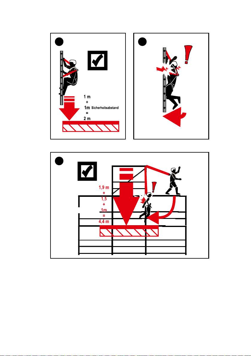
15. Der lichte Abstand unter den Füßen des Anwenders muss mindestens 2,0 m betragen,
wenn das Gerät oberhalb des Benutzers angeschlagen wird.
16. Das IKAR-Höhensicherungsgerät ist gemäß EN 360:2002, ANSI/ASSE Z359.1-2007, Z359.14-2014 im
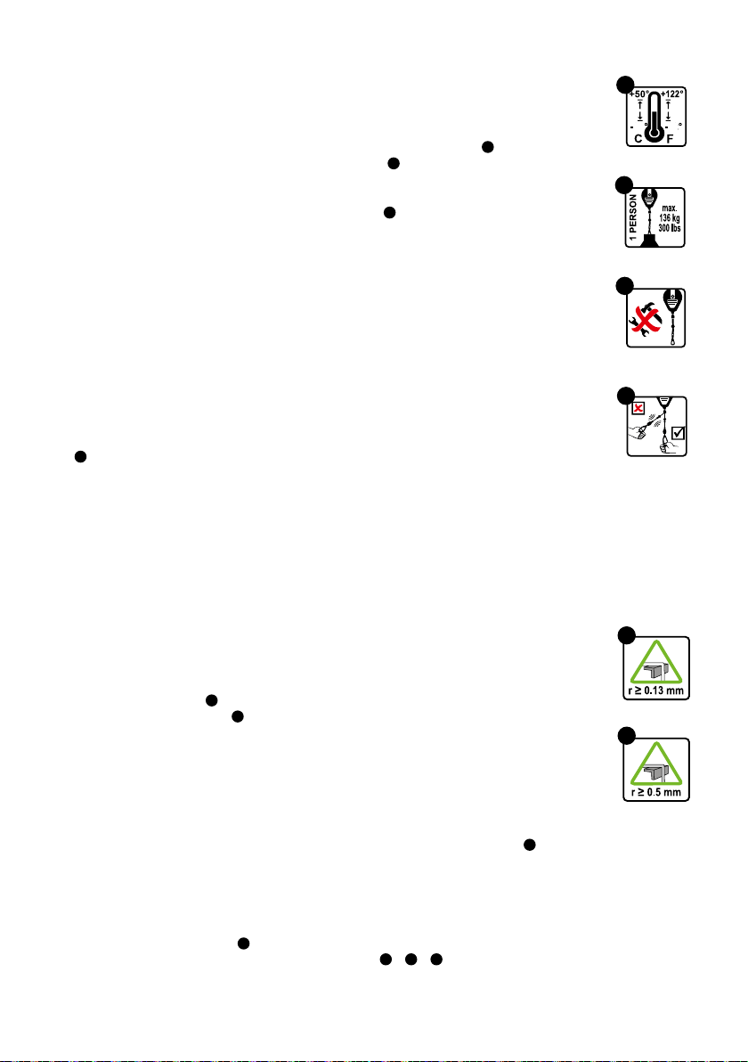
Temperaturbereich von - 40°C (-40°F) bis +50°C (+122°F) einsetzbar ( 8).
17. Die zulässige Nennlast der zu sichernden Person beträgt 136 kg ( 9).
18. Höhensicherungsgeräte sind vor den Einwirkungen von Schweißammen und -funken, Feuer, Säuren,
Laugen und ähnlichem zu schützen.
19. Es dürfen keine Veränderungen oder Reparaturen am Höhensicherungsgerät vorgenommen werden (10 ).
Reparaturen dürfen nur vom Hersteller oder vom Hersteller geschulten und autorisierten Personen
durchgeführt werden.
20. Höhensicherungsgeräte sind nur von Personen zu benutzen, die entsprechend ausgebildet oder
sachkundig unterwiesen wurden. Es dürfen keine körperlichen oder gesundheitlichen Beeinträchtigungen
vorliegen. (Alkohol-, Drogen-, Medikamenten-, Herz- oder Kreislaufprobleme)
21. Die Lebensdauer des Höhensicherungsgerätes muss bei der jährlichen Prüfung bestimmt werden, diese
beträgt je nach Beanspruchung ca. 10 Jahre.
22. Die Eignung des Einsatzes eines Höhensicherungsgeräts mit horizontaler Absturzsicherung gemäß den
aktuellen Standards muss durch geeignete Tests am kompletten System nachgewiesen werden.
Pege und Wartung
1. Das Band sollte nur unter Belastung einrollen. Auf gar keinen Fall darf man das Band ganz ausziehen
und dann loslassen, da das ruckartige Anschlagen des Karabinerhakens am Gerät einen Bruch der
Rückholfeder verursachen kann ( 11 ).
2. Einziehbare Verbindungsmittel aus Para-Aramidfasern (Textil) dürfen nur mit warmem Wasser
oder neutralen Reinigungsmitteln gereinigt werden. Keinesfalls mit Verdünnung o.ä. Reste des
Rinigungsmittels sind restlos mit klarem Wasser auszuspülen.
3. Achtung unbedingt beachten! Aufbewahrung und Transport der Höhensicherungsgeräte müssen
trocken, staub- und ölfrei erfolgen.
4. Das Trocknen von textilen Bestandteilen welche durch Reinigung oder Gebrauch nass geworden sind,
darf nur auf natürliche Weise erfolgen. Auf keinen Fall in der Nähe von Feuer o.ä. Hitzequellen trocknen.
5. Vor der Verwendung von Desinfektionsmitteln ist aufgrund der komplexen gesetzlichen
Produkteinstufungen nach den speziellen Anwendungen und den Inhaltsstoffen Kontakt mit dem
Hersteller auf zu nehmen.
Horizontaler Einsatz
Hinweis: Das Höhensicherungsgerät wurde auch für den horizontalen Einsatz und einem daraus simulierten
Sturz über die Kante erfolgreich geprüft. Dabei wurde für Höhensicherungsgeräte mit einem
Verbindungsmittel aus Drahtseil und für Höhensicherungsgeräte mit einem Verbindungsmittel aus Gurtband
ein Kanten Radius r = 0,13 mm verwendet ( 12 ). Aufgrund dieser Prüfung ist das Höhensicherungsgerät
geeignet über ähnliche Kanten mit einem Radius von r ≥ 0,5 mm nach EN und r ≥ 0,13 mm in den USA,
wie sie beispielsweise an gewalzten Stahlprolen, an Holzbalken oder an einer verkleideten, abgerundeten
Attika vorhanden sind, benutzt zu werden. Höhensicherungsgeräte mit Drahtseil sind zusätzlich auch
für eine Beanspruchung über Kanten wie z.B. die eines nachgiebigen (nicht unterstütztes) Trapezblech,
Betonfertigteilen oder von Ortbetonkanten geeignet. Ungeachtet dieser Prüfung muss bei horizontalen
oder schrägen Einsätzen bei denen ein Risiko des Absturzes über eine Kante besteht, folgendes zwingend
berücksichtigt werden:
1. Vor Arbeitsbeginn muss eine Gefährdungsbeurteilung durchgeführt werden. Handelt es sich bei der
Absturzkante um eine besonders “schneidende” und / oder “nicht gratfreie” Kante (z. B. unverkleidete
Attika oder scharfe unterstützte Blechkante), so sind vor Arbeitsbeginn entsprechende Vorkehrungen zu
treffen.
- ein Sturz über die Kante muss ausgeschlossen werden
und
- die zulässige Nennlast der Geräte für die Sturzbelastung über Kanten ( 9) darf nicht überschritten
10 11
DEUTSCH
13
17
16
rechtwinkliger Sturz über Kanten seitlicher Sturz über Kanten
14 15
3,00 m
+ 1,00 m
4,00 m
3,00 m
+ 1,00 m
4,00 m
Sicherheitsabstand
(Minimum)
Sicherheitsabstand
(Minimum)
werden
und
- vor Arbeitsbeginn muss ein Kantenschutz montieren werden
Es empehlt sich bei Zweifeln Kontakt mit dem Hersteller aufzunehmen.
2. Der Anschlagpunkt des Höhensicherungsgerätes darf nicht unterhalb der Standäche (z.B. Plattform,
Flachdach) des Benutzers liegen ( 13 ).
3. Der erforderliche Freiraum unterhalb der Kante ist in Bild 14 + 15 + 16 dargestellt.
4. Um ein Pendelsturz zu verhindern, sind Arbeitsbereich bzw. seitliche Bewegungen aus der
Mittenachse zu beiden Seiten auf jeweils max. 1,50 m zu begrenzen. In anderen Fällen sind keine
Einzelanschlagpunkte, sondern z.B. Anschlageinrichtungen Typ C (nur wenn für gemeinsame
Verwendung zugelassen) oder Typ D nach EN 795, zu verwenden.
5. Bei Verwendung des Höhensicherungsgerätes an einer Anschlageinrichtung Typ C nach EN 795 mit
horizontal beweglicher Führung ist bei der Ermittlung der notwendigen lichten Höhe unterhalb des
Benutzers auch die Auslenkung der Anschlageinrichtung zu berücksichtigen. Hierzu sind Angaben in der
Gebrauchsanleitung und die Sicherheitshinweise der Anschlageinrichtungen zu beachten.
6. Bei einem Sturz über eine Kante bestehen Verletzungsgefahren während des Auffangvorgangs durch
Anprallen des Stürzenden an Bauwerksteile bzw. Konstruktionsteile.
7. Für den Fall eines Sturzes über die Kante sind besondere Maßnahmen zur Rettung festzulegen und zu
üben.
8.
Den korrekten Abstand von Gerät zur Kante, bei horizontalem Einsatz, entnehmen Sie der Liste am Anfang
dieser Gebrauchsanleitung
( 17 ).
Zubehör
Hinweis: Um eine negative Beeinussung der sicheren Funktion der HRA-Geräte zu verhindern darf nur
vom Hersteller zugelassenes Zubehör (z.b. Rettungsklemmen nach DIN 19428:2018, Schutzhauben,
Halterungen, etc.) verwendet werden. Der Hersteller haftet nicht für Schäden an Leib und Leben des
Anwenders wenn dieser nicht zugelassenes Zubehör verwendet.

11
DEUTSCH
18 18a
Einsatz mit der Doppelaufhängung Typ HWB 1,8 DW / HWB 2 DW
Beim Einsatz der IKAR-Doppelaufhängung können 2 IKAR Höhensicherungsgeräte vom Typ HWB 1,8 / HWB 2
für das wechselseitige Anschlagen an geeigneten Anschlagpunkten zur vertikalen und horizontalen Fortbewegung
eingesetzt werden. (z.B. bei Arbeiten in Hochregallägern, Stahlbaumontagen, Industriegerüstbau oder
Vertikalaufstieg an Zweiholmsteigleitern/Steigeisengängen) Die Kombination aus Doppelaufhängung und Höhen-
sicherungsgeräte (HWB 1,8 DW / HWB 2 DW) darf nur mit Auffanggurten nach DIN EN 361:2002 verwendet
werden welche mit einer Rückenplatte zur Fixierung der Rückengurtbänder und einer Rückenauffangöse
ausgestattet sind ( 18 + 18a ).
Die Gebrauchsanleitung des Auffanggurtes ist ebenfalls zu beachten. Bei Zweifel über die Eignung des
Auffanggurtes ist der entsprechende Hersteller zu befragen. Das IKAR Höhensicherungsgerät Typ HWB 1,8
DW / HWB 2 DW ist in Verbindung mit den IKAR Sonderwirbeln Typ DW entsprechend der EN 360:2002 und
CNB 11.060:2008 (horizontaler Einsatz mit einer Sturzbelastung über Kanten r=0,5 mm) erfolgreich geprüft und
zugelassen. (siehe Gebrauchsanleitung und Sicherheitshinweise)
1. Es darf nur die IKAR Doppelaufhängung Typ DW mit den IKAR Höhensicherungsgeräten Typ
HWB 1,8 DW / HWB 2 DW verwendet werden. Keine anderen Kombinationen sind zulässig. Adapter anderer
Hersteller oder andere Höhensicherungsgeräte dürfen nicht verwendet werden.
2. Die IKAR Höhensicherungsgeräte werden am Drehwirbel von einer unterwiesenen Person mittels der dafür
vorgesehenen Spezialschrauben M8 Güte 8.8 mit der Doppelaufhängung verbunden ( 30 + 31 + 32 + 33 ).
Das Anzugsmoment der Schrauben beträgt 18 Nm, zusätzlich sind die Schrauben mit einer mittelfesten
Schraubensicherung zu sichern.
3. Mit dem Steckbolzen kann jetzt der Adapter zwischen der Rückenplatte und den Gurtbändern des
Auffanggurtes verbunden werden (18 ).
4. Die idealen Anschlagpunkte für die Karabinerhaken der einziehbaren Verbindungsmittel müssen sich
entweder über oder hinter dem Anwender und nicht tiefer als Hüfthöhe benden ( 19 + 20 + 25 + 24 + 26 + 29 ).
Ausnahme: Bei Arbeiten auf der Standäche des Anwenders (22 + 23 ). z.B. bei Containermontagen,
Flachdachabsturzsicherungen und Stahlbaumontagen mit konstruktions-bedingten, größeren Abständen.
Jedoch nicht bei Arbeiten unterhalb der Standäche des Anwenders.
Dabei sind beide Höhensicherungsgeräte mit den Verbindungselementen der einziehbaren Verbindungsmittel
mit den Anschlagpunkten zu verbinden.
5. Mögliche Verletzungen des Anwenders im Falle eines Sturzes durch Anprallen an Konstruktionsteile oder durch
die einziehbaren Verbindungsmittel (z.B. Hautabschürfungen unter den Armen) oder durch ein unkontrolliertes
Herumschleudern eines nicht mit dem Anschlagpunkt verbundenen Höhensicherungsgerätes können nicht
ausgeschlossen werden ( 28 + 29 ).
6. Werden die Höhensicherungsgeräte zur Absturzsicherung vom Anwender nicht mehr benötigt, so sind die
Karabinerhaken der einziehbaren Verbindungsmittel mit einem geeigneten Punkt des Auffanggurtes
(z.B. Halteösen) zu verbinden.
7. Vor der Benutzung ist der Anwender durch praktische Übungen mit den Eigenarten der notwendigen
Bewegungsabläufe und Anschlagtechniken zu unterweisen, insbesondere ist dabei ein Verdrehen/Kreuzen der
einziehbaren Verbindungsmittel zu verhindern damit der Einzug der Verbindungsmittel nicht behindert wird.
8. Der lichte Abstand unter den Füßen des Anwenders sind zwingend zu beachten
(19 + 20 + 22 + 23 + 24 + 25 + 27 + 29 ).

12 13
DEUTSCH
19 20 21
2,0 m
22 23 24
25 26
13
DEUTSCH
Sicherheitsabstand
27 28
29

14 15
DEUTSCH DEUTSCH
32
18 Nm
18 Nm
2.
1.
33
18 Nm
18 Nm
2.
1.
31
2.
3.
1.
30
2.
3.
1.
1. Verriegelung mit z.B. Stift eindrücken
2. Bolzen links herum drehen
3. Bolzen herausziehen
Montage der Doppelaufhängung

15
DEUTSCH
34
Verwendung zum Schutz gegen Absturz in Arbeitskörben von
Hubarbeitsbühnen HWB 1,8
Das Höhensicherungsgerät ist zum Schutz gegen Absturz beim Herausschleudern (Katapult- oder
Peitscheneffekt) des Benutzers in Verbindung mit der Verwendung eines Auffanggurtes nach EN 361:2002
in Arbeitskörben von Hubarbeitsbühnen die mit geeigneten Anschlagpunkten ausgestattet sind, geprüft und
zugelassen.
Die Bedienungsanleitung der Hubarbeitsbühne ist zu beachten!
Folgendes ist dabei unter anderem zu beachten:
1. Grundsätzlich können Verletzungen des Anwenders z.B. Anprallen am Arbeitskorb oder dem Ausleger
der Hubarbeitsbühne beim Einsatz des Höhensicherungsgerätes nicht ausgeschlossen werden.
2. Das Höhensicherungsgerät darf nur in Verbindung mit Auffanggurten nach EN 361:2002 mit Rücken- und
Brustauffangöse verwendet werden.
3. Es dürfen nur ausreichend tragfähige Anschlagpunkte ( 34 ) verwendet werden die sich mindestens 35
cm unter dem Handlauf benden. Bei der Verwendung von höher gelegenen Anschlagpunkten am
Arbeitskorb ist die sichere Funktion des Höhensicherungsgerätes nicht mehr gewährleistet.
4. Das Höhensicherungsgerät wird mit dem geeigneten Anschlagpunkt des Arbeitskorbes mittels
Verbindungselement (max. Länge 110 mm) nach EN 362:2004 verbunden. Das einziehbare
Verbindungsmittel wird mit seinem Verbindungselement mit der Auffangöse des Auffanggurtes
verbunden. Der Einsatz einer Verlängerung in Verbindung mit der Brustauffangöse des Auffanggurtes ist
nicht zulässig.
5. Das Höhensicherungsgerät wird an der Rückenauffangöse des Auffanggurtes mittels
Verbindungselement (max. Länge 110 mm) nach EN 362:2004 verbunden. Das einziehbare
Verbindungsmittel wird mit seinem Verbindungselement an einem geeigneten Anschlagpunkt am
Arbeitskorb befestigt ( 37 + 39 ).
Der Einsatz einer Verlängerung zwischen Rückenauffangöse des Auffanggurtes und des
Höhensicherungsgerätes ist nicht zulässig.
6. Bei der Auswahl der Auffangösen, des Auffanggurtes und den Anschlagpunkten im Arbeitskorb ist
darauf zu achten, dass immer die kürzeste Verbindung zwischen Auffangöse des Auffanggurtes und
Anschlagpunkt hergestellt wird. Veränderungen des Systems sind nicht zulässig.
7. Um ein Herausschleudern aus dem Arbeitskorb während der Fahrt der Hubarbeitsbühne zu verhindern,
ist die Verbindung zwischen einem vorderen Anschlagpunkt im Bereich des Bedienpultes (max. Höhe
Knieleiste oder tiefer) und der Brustauffangöse des Auffanggurtes zu wählen (36 ). Wahlweise kann
auch ein hinterer Anschlagpunkt und die Rückenauffangöse eines Auffanggurtes ohne Einsatz einer
Verlängerung gewählt werden (37 + 38 ).
8. Um ein Aufprallen des Benutzers auf den Boden oder ein Aufprallen auf andere Teile in der Umgebung
beim Herausschleudern ausschließen zu können, muss der Freiraum unterhalb des Arbeitskorbes min.
2,0 m betragen ( 41 ).
9. Die Gesamteinsatzlänge des HWB 1,8 inkl. aller Verbindungselemente darf 1,8m nicht überschreiten.

16 16
DEUTSCH
33 34 35 36
36 3735 36 37 38 39
+ 1,00 m
1,00 m
2,00 m
4040
Sicherheitsabstand
(Minimum)
Anwendung HWB 1,8 in Arbeitskörben von Hubarbeitsbühnen
Sicherheitshinweise

17
ENGLISH
1
2
3
4
5
6
6a
6b
7
Instructions for use HWB 1.8 / HWB 2
Safety information
1. Fall arresters according to EN 360:2002, ANSI/ASSE Z359.14-2014 constitute personal protective
equipment (PPE) for the purposes of protection against falls. In combination with a full body harness
according to EN 361:2002, ANSI/SSE Z359.1-2007, this system serves to protect persons working at
heights where a falling hazard exists. (e.g. roofs, scaffoldings, ladders and shafts). Only use the device
as intended.
Connection elements according to EN 362:2004: The corresponding instruction manual for the
connection elements used (snap hooks) must be read and followed.
2. Failure to observe these instructions for use and the safety information can lead to fatal injuries ( 2).
In case of a fall, it should be ensured that the person is not left hanging for longer than 15 minutes
(danger of shock).
3. For use with the fall arresters, only full body harnesses according to EN 361:2002, ANSI/ASSE Z359.1-
2007 are approved (other harnesses are not permitted) ( 1).
4. One piece of equipment can only be used to protect one person at a time, but can be used by several
persons one after the other. A rescue plan should be in place taking into account all potential incidents
which may occur during work.
5. A sufciently strong, suitable fastening point corresponding to the national regulations with a min.
load-bearing capacity of 9 kN (North America 22.2 kN) should be chosen for the device. The fastening is
done with snap hooks according to EN 362:2004 / ANSI/ASSE Z359.12-2009 (mountaineering karabiner
hooks) or sling according to EN 795, whereby the sling is pulled through the bracket of the device and
closed with a secured snap hook ( 3). In case of devices with rotatable swivel eye hanging, the snap
hook is connected to the anchorage point and rotatable swivel eye. For use of the fall arrester on a type
C anchor device according to EN 795 / North America 22.2 kN (only if approved for shared use) with a
vertically exible anchor line the excursion of the anchor device should be considered when determining
the required clearance underneath the person using the device. The information provided in the
instructions for use and the safety information of the anchor device should be observed in this context.
6. If possible, the device should be positioned vertically above the head of the person to be secured in order
to prevent any swinging movement during the fall. The mounting of the device should ensure adaptation
to any potential webbing deviations. After attaching the device to the anchor point, the end of the
retractable lanyard (snap hook) should be fastened to the D-ring of the full body harness. Lanyards which
are not self-locking (snap hooks) should be screwed together using the retention nut ( 4). The instruction
manual must be read and followed!
7. After attaching the fall arrester to a suitable anchor point (according to EN795 / DGUV R 112-198 / ANSI/
ASSE Z359.1-2007) and fastening the anyard (snap hook) to the catching eyelet of the full body harness
(according to EN361:2002 / ANSI / ASSE Z359.1-2007) worn by the worker, the personal protection of the
worker is ensured.
8. A visual inspection of the device and a check of the readability of the product labelling is required prior to
each instance of use.
9. In addition, a functional test is required prior to each instance of use. This is done by jerking out the
webbing or by applying a weight of at least 15kg. In both cases, the drum brake should engage ( 5).
10. Fall arresters should not be used to secure persons above bulk material or substances which would allow
a person to sink in ( 6).
11. If a device has been damaged and / or has sustained wear due to a fall (tripped fall indicator! (6a + 6b )
or if any doubt exists with regard to the safe condition of the device, it should be withdrawn from use
immediately. It may only return to use following inspection and written approval by a competent person or
the manufacturer.
12. Depending on wear, but every twelve months as a minimum, fall arresters should be inspected by the
manufacturer or by persons trained and authorised by the manufacturer. This inspection should be
documented in the supplied log book. Effectiveness and durability of the fall arrester depend on regular
inspection.
13. If the thread breaks or the webbing is bent or roughened, the fall arrester should be sent to the overhaul
workshop. The webbing should be replaced there. ( 7).
14. DGUV R 112-198 (Use of personal protective equipment against falls) and DGUV R 112-199 (Rescue
from heights and depths with personal protective equipment) as well as DGUV Information 212-870 (Full
18 19
ENGLISH ENGLISH
9
40 40
8
10
11
12
12a
body harnesses and lanyards for full body harnesses) should be observed.
15. The clearance below the feet of the person using the device should be at least 2.0m if the device is
attached above the person using the device.
16. The IKAR fall arrester can be used in conformity with EN 360:2002, ANSI/ASSE Z359.1-2007, Z359.14-
2014 within a temperature range between - 40°C (-40°F) and +50°C (+122°F) ( 8).
17. The max. working load of the person to be secured is 136kg ( 9).
18. Fall arresters should be protected against the impact of welding ames and sparks, re, acidic
substances, alkaline substances and the like.
19. Do not apply any modications or repairs to the fall arrester (10 ).
Repairs may only be carried out by the manufacturer or persons trained and authorised by the
manufacturer.
20. Fall arresters may be used only by persons who have been trained accordingly or have been instructed
by a competent person. The person using the device should not have any physical or health impairments.
(Alcohol, drug or medication abuse, cardiovascular problems)
21. The service life of the fall arrester should be determined during each annual inspection; depending on
wear, it is approx. 10 years.
22. The suitability for use of a fall arrester with horizontal fall protection in conformity with the current
standards should be veried by suitable tests on the complete system.
Care and maintenance
1. The webbing should be rolled up only with a load applied. Never pull the webbing out entirely and then
release it, as the sudden impact of the snap hook on the device may cause the return spring to break
(11 ).
2. Retractable connection elements made of para-aramid bres (textile) may only be cleaned with warm
water or neutral cleaning agents. Never use thinner or similar. Any residues from the cleaning agent must
be rinsed out completely with clean water.
3. Attention: Please note! The fall arresters should be stored and transported in a dry, dust-free and oil-
free environment.
4. Textile components which have become wet due to cleaning or use should be dried by natural means
only. Do not dry near re or similar sources of heat.
5. Before using disinfectants, you have to contact the manufacturer due to the complex legal product
classications based on the specic applications and constituents.
Horizontal use
Please note: The fall arresting device has been successfully tested for horizontal application and a fall
over the edge simulated from this. Here an edge radius r = 0.13 mm was used for fall arresting devices with
fastener made from webbing ( 12 ). Based on this test, the fall arresting device is suitable for use over similar
edges with a radius of r ≥ 0.5 mm (12a) according to EN and r ≥ 0.13 mm in the USA, as are typically present
on rolled steel proles, on wooden beams or on a panelled, rounded fascias.
1. A risk assessment should be carried out prior to starting work. If the edge over which a fall may occur is a
particularly “cutting” edge and / or is not free of burrs (e.g. uncovered parapet or sharp, reinforced sheet
metal edge), appropriate precautions should be taken prior to starting work.
- a fall over the edge should be excluded
and
- the max. working load of the devices for the stress sustained during a fall over edges ( 9) should not be
exceeded
and
- an edge protector should be installed prior to starting work
In cases of doubt, it is recommended to contact the manufacturer.
2. The anchor point of the fall arrester should not be below the surface (e.g. platform, at roof) the person
using the device is standing on ( 13 ).
3. The required clearance below the edge is shown in Figures 14 + 15 + 16 .
4. In order to prevent a fall with a swinging movement, the working area and the lateral movement from the
centre line should be limited to max. 1.50 m on both sides. In other cases, no single anchor points should

19
ENGLISH ENGLISH
13
17
16
Fall over edges at right angle Fall over edges with lateral offset
14 15
Safe distance
(minimum)
Safe distance
(minimum)
3.00m
+ 1.00m
4.00 m
3.00m
+ 1.00m
4.00 m
be used, but e.g. type C anchor devices (only if approved for shared use) or type D devices according to
EN 795.
5. For use of the fall arrester on a type C anchor device according to EN 795 with a horizontally ecible
anchor line, the excursion of the anchor device should also be considered when determining the required
clearance underneath the person using the device. The information provided in the instructions for use
and the safety information of the anchor devices should be observed in this context.
6. In case of a fall over an edge, there is a danger of injury during the process of arresting the fall due to the
falling person hitting parts of the building or structure.
7. Special measures for rescue should be dened and trained for cases of falls over an edge.
8.
For the correct distance from the device to the edge in case of horizontal use see the list at the beginning of
these instructions for use
( 17 ).
Accessories
Please note: In order to prevent a negative impact on the safe function of the fall arresting devices, it is
only permitted to use accessories approved by the manufacturer (e.g. rescue clamps to DIN 19428:2018,
protective covers, etc.). The manufacturer is not liable for any accidents involving the life and limb of the user
if using non-approved accessories.

20 21
ENGLISH
ENGLISH
18a
18
Use with the type HWB 1.8 DW / HWB 2 DW double suspension
When using the IKAR double suspension, 2 IKAR type HWB 1.8 / HWB 2 fall arresters can be used for reciprocal
fastening at suitable anchor points for vertical and horizontal movements. (e.g. when working in high-bay
warehouses, steel structure assemblies, industrial scaffolding or vertically climbing double-rail ladders/manhole
steps) The combination consisting of the double suspension and fall arresters (HWB 1.8 DW / HWB 2 DW) may
only be used together with full body harnesses according to EN 361:2002 which are equipped with a back plate for
the xation of the back webbings and a D-ring on the back ( 18 + 18a ).
The instruction manual for the full body harness should also be followed. If in doubt about the suitability of the full
body harness, consult the corresponding manufacturer. The IKAR fall arresting device type HWB 1.8 DW / HWB 2
DW has been successfully tested and approved in conjunction with the IKAR special swivel type DW corresponding
to EN 360:2002 and CNB 11.060:2008 (horizontal use with a fall impact over edges r=0.5 mm) (see instruction
manual and safety information).
1. Only the IKAR type DW double suspension with the IKAR type HWB 1.8 DW / HWB 2 DW fall arresters may be
used. No other combinations are admissible. Adapters of other manufacturers or other fall arresters should not
be used.
2. The IKAR fall arresters are connected by an instructed person at the swivel by means of the provided M8
quality 8.8 special screws to the double suspension ( 30 + 31 + 32 + 33 ).
The tightening torque of the screws is 18 Nm. In addition to this, the screws should be secured with a medium
screw lock.
3. Using the locking pin, the adapter between the back plate and the webbings of the full body harness can be
connected (18 ).
4. The ideal anchor points for the snap hooks of the retractable lanyard should be either above or behind the
person using the device and should not be lower than waist level (19 + 20 + 25 + 24 + 26 + 29 ).
Exception: When performing work on the surface the person using the device is standing on ( 22 + 23 ).
E.g. in the case of container assemblies, at roof fall protection and steel structure assemblies with design-
related, larger distances. But not when working below the surface the person using the device is standing on.
With the connectors of the retractable lanyard, both fall arresters should be connected to the anchor points.
5. Possible injuries of the person using the device caused in the event of a fall by hitting parts of the structure or
by the retractable lanyard (e.g. skin abrasions under the person’s arms) or by the uncontrolled swirling around
of a fall arrester that is not connected to the anchor point cannot be excluded ( 28 + 29 ).
6. If the fall arresters for fall protection are no longer required by the person using the device, the snap hooks of
the retractable lanyard should be connected with a suitable point of the full body harness (e.g. holding D-ring).
7. Prior to any use, the person using the device should be instructed by means of practical exercises with the
particularities of the required motion sequences and anchoring technique. In particular, the retractable
lanyard
should be prevented from twisting/crossing so that the retraction of the lanyard is not impaired.
8. The clearance below the feet of the person using the device should be observed at all times
(19 + 20 + 22 + 23 + 24 + 25 + 27 + 29 ).
Other manuals for HWB 1.8
1
This manual suits for next models
3
Table of contents
Languages:
Other IKAR Safety Equipment manuals


