manuals.online logo
Brands
  1. Home
  2. •
  3. Brands
  4. •
  5. iNels
  6. •
  7. Security Sensor
  8. •
  9. iNels RFSF-100 User manual

iNels RFSF-100 User manual

RFSF-100
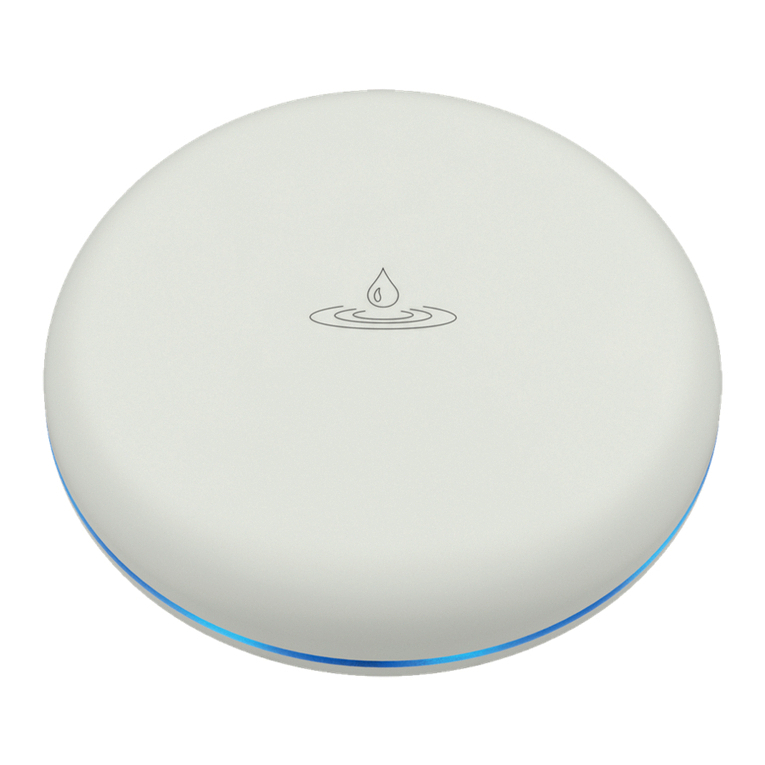
Flood detector
EN
02-17/2020 Rev.0
Made in Czech Republic
Characteristics /
• The flood detector is used to detect water leakage - the activation occurs the moment the
flooding of the contacts located on the underside of the detector occurs.
• Upon detecting water, the flood detector immediately sends a signal to the switched unit, which
further switches on a pump, GSM gate or closes a pipe valve.
• It brings a quick solution to learn about unwanted flooding in your bathroom or kitchen, to which
you can immediately respond with a paired actuator. Which can close, for example, the water
supply to a flowing washing machine.
• Flood detection is signalled by vibration, optical and acoustic signalling.
• Low battery signaling 5 times by flashing the LED every 15 minutes or a warning in the iHC
application.
• Range up to 160 m (in open space); if the signal is insufficient between the controller and unit, use
the signal repeater RFRP-20 or protocol component RFIO2 that support this feature.
1/4
Radio frequency signal penetration through various construction materials /
80 - 95 % 80 - 90 % 60 - 90 % 20- 60 % 0 - 10 %
wooden structures
with plaster boards common glass brick walls reinforced
concrete metal partitions
ELKO EP declares that the RFSF-100 type of radio equipment complies with Directive 2014/53 / EU.
The full EU Declaration of Conformity is available at:
www.elkoep.com/flood-detector-rfsf-100
x
RFRP-20
Placement recommendations /
5-10 kΩ
2-5 kΩ
2-15 kΩ
15-25 kΩ
0.5-2 kΩ
~0.03 kΩ
~2.2 kΩ
~5 kΩ
~5 kΩ
~18 kΩ
~1 kΩ
~1 kΩ
~1 kΩ
~1 kΩ
~1 kΩ
~2.2 kΩ
~2.2 kΩ
~2.2 kΩ
~18 kΩ
Liquids suitable for detection /
Type of liquid
Drinking water
Well water
River water
Rain water
Waste water
Seawater
Salt water
Natural / hard water
Chlorinated water
Condensed water
Milk
Milk serum
Fruit juices
Vegetable Juices
Broths
Wine
Beer
Coffee
Soap toam
Inadmissible liquids /
Conductivity of liquids /
• Demineralised water
• Deionised water
• Bourbon
• Gasoline
• Oil
• Liquid gases
• Paraffin
• Ethylene glycol
• Paints
• High alcohol-content liquids
* Resistivity characterizes the resistive
properties of materials which conduct
electric current.
After inserting the battery, pairing with the actuator and setting the required alarm, place the de-
tector on a flat, non-conductive surface where flooding is expected. CAUTION: The flood detector
detects only the presence of liquid that has reached the sensor.
We recommend placing the detector in a visible place.
The detector is intended for indoor use only.
ELKO EP, s.r.o. | Palackého 493 | 769 01 Holešov, Všetuly | Czech Republic | e-mail: [email protected] | Support: +420 778 427 366
ELKO EP Poland, sp. z o. o. | ul. Motelowa 21 | 43-400 Cieszyn | Polska | e-mail: [email protected] | GSM: +48 785 431 024
www.elkoep.com / www.elkoep.pl
Detektor zalania
PL
Charakterystyka
Przenikanie fal radiowych przez różnego rodzaju materiały budowlane
ściana z cegły
konstrukcje drewniane
z płytami gipsowo-
kartonowymi
ściana
żelbetowa
ścianki
metalowe zwykłe szkło
• Czujnik zalania służy do wykrywania wycieku wody – do zadziałania dochodzi po zalaniu styków
znajdujących się na spodzie czujnika.
• Po wykryciu natychmiast nadaje polecenie do urządzenia załączającego, które załącza pompę,
bramkę GSM lub zamyka zawór rurociągu. Daje szybkie rozwiązanie pozwalające dowiedzieć
się o niechcianym zalaniu w łazience lub kuchni, na które możesz natychmiast zareagować
sparowanym aktorem, który może na przykład zamknąć dopływ wody do wyciekającej pralki.
• Wykrycie zalania sygnalizowane wibracjami, sygnalizacją optyczną i akustyczną.
• Sygnalizacja niskiego poziomu baterii 5-krotnym mignięciem diody LED co 15 min. lub w aplikacji iHC.
• Zasięg do 160 m (w wolnej przestrzeni), w przypadku niewystarczającego sygnału pomiędzy
sterownikiem oraz urządzeniem użyj wzmacniacza sygnału (repeatera) RFRP-20 lub urządzenia
Zprotokołem RFIO2, wspierającego tę funkcję.
Po włożeniu baterii, sparowaniu z aktorem i ustawieniu wymaganej sygnalizacji, należy umieścić
czujnik na płaskiej, nieprzewodzącej powierzchni, na której spodziewane jest zalanie. UWAGA: czuj-
nik zalania wykrywa tylko obecność cieczy, która dotarł do czujnika.
Zalecamy umieszczenie detektora w widocznym miejscu.
Detektor jest przeznaczony wyłącznie do użytku wewnątrz.
Zalecenia dotyczące umieszczenia
Resistivity / Opór [Ωcm]*
Ciecze odpowiednie do wykrywania
Rodzaj cieczy
woda pitna
woda ze studni
woda z rzeki
woda deszczowa
ścieki
woda morska
słona woda
woda naturalna / twarda
chlorowana woda
skroplona woda
mleko
serwatka
sok owocowy
sok warzywny
zupa
wino
piwo
kawa
mydliny
Nieodpowiednie ciecze
Przewodnictwo cieczy
• woda demineralizowana
• dejonizowana woda
• whisky
• benzyna
• olej
• ciekłe gazy
• parafina
• glikol etylenowy
• farby
• ciecze o wysokiej zawartości alkoholu
* Opór właściwy charakteryzuje właściwości
rezystancyjne substancji przewodzących prąd
elektryczny.
Niniejszym firma ELKO EP, s.r.o. deklaruje, że typ urządzenia radiowego RFSF-100 jest zgodny
z dyrektywą 2014/53 / UE. Pełny tekst deklaracji zgodności UE jest dostępny na następujących
stronach internetowych: www.elkoep.com/flood-detector-rfsf-100
RFSF-100
Flood detector
EN
02-17/2020 Rev.0
Made in Czech Republic
ON
1 2 3
The detector is compatible with:
• switching components
all switching components of the RF Control system (except blinds), which are marked with the
RFIO2 communication protocol, eg RFSA-11B, RFSA-66M, RFUS-61, RFSC-61 ...
• system conponents
eLAN-RF, RF Touch, central units of the iNELS BUS system (CU3-0xM)
Compatibility /
ON
1 2 3
+
-
+
-
12 3
a.
b.
a.
d.
c.
f.
b.
e.
When handling a device unboxed it is important to avoid contact with liquids.
Avoid unnecessary contact with the components of the device.
Safe handling /
2/4
Indication, settings /
a. Screw
b. Probes pads
c. Seal
d. Insulating foil
e. DIP
f. Battery
Before installing, open the detector cover with a screwdriver (Fig. 1). The adjustment settings are
located inside the detector. Remove the insulating foil, check the correct placement of the battery.
Indication
• Activation of the device: after removing the insulating foil or inserting the batteries, the blue
LED lights up for 2 seconds and at the same time a message is sent to the device.
• Alarm: when the contacts are flooded, the detector sends a message to the paired component
and at the same time signals an alarm condition.
Alarm signaling: 1x second LED flash alternates with 1x "beep" at second intervals.
Alarm signaling when the battery is low: at second intervals, the LED flashes alternately with 2x
"beeps".
• Alarm termination: after a few seconds of the flood drop (interruption of the connection of the
sensing contacts) it sends a message to the paired component and switches off the signaling.
• Weak batteries: the detector flashes once and at a short time interval flashes 4 more times, this
signaling is repeated in 15 minutes. interval until the batteries are completely discharged.
DIP switch settings
• Position 1:
OFF - normal function, ie: in case of flooding, the (relay) contact of the assigned component
switches
ON - negated function, ie: during flooding it opens the (relay) contact of the assigned compo-
nent, at the end of flooding the contact is closed
• Position 2:
OFF - for pairing with a switching component - does not periodically send information about
the current status
ON - for pairing with a system component (eLAN-RF, RF Touch, iNELS control panel) - sends a
status message periodically after 120 minutes and when the status changes (flooding / end of
fl o o d i n g )
• Position 3:
OFF - switched off sound signaling when contacts are flooded
ON - on audible alarm when contacts are flooded
Save DIP switch settings
Set the DIP as required. Insert the batteries into the battery holder (observe the polarity). The
blue LED on the detector lights up for 2 seconds - this saves the DIP switch settings.
Note: If the LED does not light up after inserting the batteries, you must reset the detector, ie:
remove the batteries and connect the inside of the battery holders with light pressure (Fig.3)
and then re-insert the batteries.
ON
1 2 3
ELKO EP, s.r.o. | Palackého 493 | 769 01 Holešov, Všetuly | Czech Republic | e-mail: [email protected] | Support: +420 778 427 366
ELKO EP Poland, sp. z o. o. | ul. Motelowa 21 | 43-400 Cieszyn | Polska | e-mail: [email protected] | GSM: +48 785 431 024
www.elkoep.com / www.elkoep.pl
Detektor zalania
PL
Nie pozwól na kontakt z cieczami w trakcie korzystania z urządzenia bez obudowy.
Nie dotykaj części wewnątrz urządzenia.
Bezpieczna manipulacja urządzeniem
a.śrubka
b. styki skanujące
c. uszczelka
d. folia izolacyjna
e. DIP
f. baterie
Przed uruchomieniem należy otworzyć obudowę czujnika śrubokrętem (rys. 1). Elementy regulacyj-
ne znajdują się wewnątrz czujnika. Zdejmij folię izolacyjną, sprawdź prawidłowe umieszczenie baterii.
Wskazanie
• Aktywacja urządzenia: po zdjęciu folii izolacyjnej lub włożeniu baterii niebieska dioda LED zapa-
la się na 2 sekundy i jednocześnie nadane jest polecenie do urządzenia.
• Alarm: w przypadku zalania styków czujnik nadaje wiadomość do sparowanego urządzenia i
jednocześnie sygnalizuje stan alarmowy.
Sygnalizacja alarmu: w sekundowych odstępach dioda LED miga na przemian z 1x „sygnałem
dźwiękowym”.
Sygnalizacja niskiego poziomu naładowania baterii: co 2 sekundy dioda miga na przemian z 2x
„sygnałem dźwiękowym”.
• Zakończenie alarmu: po kilku sekundach od spadku zalania (przerwanie połączenia styków czuj-
nika) nadaje wiadomość do sparowanego urządzenia i wyłącza sygnalizację.
• Słabe baterie: czujnik miga 1 raz oraz miga jeszcze 4 razy w niewielkim odstępie czasu, sygnaliza-
cja ta jest powtarzana w 15 minutowych odstępach, aż do momentu całkowitego rozładowania
baterii.
Ustawienia przełącznika DIP
• pozycja 1:
OFF – funkcja normalna, tzn. podczas zalania załącza styk (przekaźnikowy) przypisanego urządzenia
ON – funkcja zanegowana, tzn. podczas zalania rozłącza styk (przekaźnikowy) przypisanego
urządzenia, po zakończeniu zalania styk jest zwarty
• pozycja 2:
OFF – do sparowania z urządzeniem załączającym – nie nadaje wiadomości o aktualnym stanie
ON – do sparowania z urządzeniem systemowym (eLAN, RF Touch, centrala iNELS) – wiadomość
o aktualnym stanie jest cyklicznie nadawana po 120 minutach oraz przy zmianie stanu (zalanie /
koniec zalania)
• pozycja 3:
OFF – sygnalizacja dźwiękowa wyłączona podczas zalania styków
ON – sygnalizacja dźwiękowa włączona podczas zalania styków
Zapis ustawień przełącznika DIP
Ustaw przełącznik DIP zgodnie z wymogiem. Włóż baterie do uchwytu (przestrzegaj bieguno-
wość). Niebieska dioda LED czujnika zapala się na 2 sekundy – oznacza to zapisanie ustawień
przełącznika DIP.
Uwaga: Jeżeli po włożeniu baterii dioda LED nie zaświeci się, należy zresetować czujnik, tzn.: wyj-
mij baterie i lekko dociśnij wnętrze uchwytów baterii (rys. 3), a następnie ponownie włóż baterie.
Czujnik jest kompatybilny z:
• urządzenia załączające
Wszystkie urządzenia załączające systemu RF Control (z wyjątkiem żaluzjowych), które są ozna-
czone protokołem komunikacyjnym RFIO2, np. RFSA-11B, RFSA-66M, RFUS-61, RFSC-61 …
• urządzenia systemowe
eLAN-RF, RF Touch, jednostki centralne systemu iNELS BUS (CU3-0xM)
Sygnalizacja, ustawienie
Zgodność
RFSF-100
Flood detector
EN
02-17/2020 Rev.0
Made in Czech Republic
Functions and programming with compatible switches /
Description of function /
4
+
-
+
-
5a
PROG > 5s
1 x
+
-
+
-
t = 2s...60min.

5b
6
PROG < 1s
1 x
Programming with the RF control unit /
address /
The address listed on the back of the device is used for programming with
RF system components.
Programming /
+
-
+
-
7
3/4
The detector is designed to detect the presence of water in flooded areas. After detection, it im-
mediately sends a command to the switching component, which continues to switch according
to the set function.
1
+
-
2
+
-
Press of programming button on
compatible actuator for 1 second will
activate actuator into programming
mode. LED is flashing in 1s interval.
3
PROG > 1s
1 x
Use a screwdriver to open the detector. Remove one of the batteries from
the holders.
Only for functions 5 and 6:
Insert / remove the battery accord-
ing to the required function (5x or
6x). Pressing the programming but-
ton for more than 5 seconds puts
the device in to timer mode. The
LED flashes twice at second intervals.
When the button is released, the de-
lay time starts to count.
Only for functions 5 and 6:
After the required time has elapsed
(between 2 s ... 60 min), end the tim-
ing mode by inserting the battery
into the detector. This saves the set
time interval in the device's memory.
Insert / remove the battery into the
detector according to the required
function, ie: 1x battery insertion /
removal - function 1, 2x battery inser-
tion / removal - function 2... Each in-
sertion must be signaled by flashing
blue LEDs, there must be a delay of
1 s between individual inserts.
Replace the seal, attach the front
cover - make sure the correct loca-
tion. Screw in, tighten the screws to
maintain IP protection.
Press of programming button on re-
ceiver RF shorter then 1 second will
finish programming mode.
ELKO EP, s.r.o. | Palackého 493 | 769 01 Holešov, Všetuly | Czech Republic | e-mail: [email protected] | Support: +420 778 427 366
ELKO EP Poland, sp. z o. o. | ul. Motelowa 21 | 43-400 Cieszyn | Polska | e-mail: [email protected] | GSM: +48 785 431 024
www.elkoep.com / www.elkoep.pl
Detektor zalania
PL
Za pomocą śrubokręta otwórz czujnik
Załóż uszczelkę oraz przednią pokry-
wę – upewnij się, że jest we właściwej
pozycji. Dokręć śruby, aby zachować
stopień ochrony IP.
Funkcja oraz programowanie za pomocą kompatybilnych przełączników
Detektor przeznaczony jest do wykrywania obecności wody w zalanych pomieszczeniach. Po
wykryciu zalania natychmiast nadaje polecenie do urządzenia przełączającego, które kontynuuje
przełączanie zgodnie z ustawioną funkcją.
Tylko dla funkcji 5 i 6:
Włóż / wyjmij baterię zgodnie z wy-
maganą funkcją (5x lub 6x). Naciśnię-
cie przycisku programowania na dłu-
żej niż 5 sekund ustawia urządzenie
w tryb timera. Dioda LED miga 2x w
sekundowych odstępach. Po zwol-
nieniu przycisku zaczyna się odlicza-
nie czasu opóźnienia.
Tylko dla funkcji 5 i 6:
Po upływie wymaganego czasu (od
2 s do 60 min) zakończ tryb timera
wkładając baterię do czujnika. Przez
to ustawiony przedział czasu zapisa-
ny zostaje w pamięci urządzenia.
Naciśnij przycisk programowania na
kompatybilnym urządzeniu na 1 se-
kundę, aby wprowadzić urządzenie
w tryb programowania. Dioda LED
miga w odstępach 1-sekundowych.
Włóż / wyjmij baterię do czujnika
zgodnie z wymaganą funkcją tzn.:
1x wkładanie / wyjmowanie baterii
- funkcja 1, 2x wkładanie / wyjmo-
wanie baterii - funkcja 2 ... Każde
włożenie musi być sygnalizowane
miganiem niebieskich diod LED, po-
między poszczególnymi włożeniem
musi występować opóźnienie 1s.
Do programowania z urządzeń systemowych RF służy adres podany z tyłu
urządzenia.
Wyjmij jedną z baterii z uchwytów.
Opis funkcji
Programowanie
Programowanie z urządzeń systemowych RF
adres
Po naciśnięciu przycisku PROG na
urządzeniu RF krótszym niż 1 sekun-
da, następuję koniec trybu progra-
mowania.
RFSF-100
Flood detector
EN
02-17/2020 Rev.0
Made in Czech Republic
Replacement of a battery /
1
+
-
+
-
3
Use a screwdriver to open the detector. Replace the batteries and check the
correct location (when the batteries
are inserted, the blue LED lights up
for 2 seconds and a message is sent
to the device at the same time).
Replace the seal, attach the front
cover - make sure the correct loca-
tion. Screw in, tighten the screws to
maintain IP protection.
+
-
+
-
2
4/4
Instruction manual is designated for mounting and also for user of the device.
It is always a part of its packing. Installation and connection can be carried out
only by a person with adequate professional qualification upon understanding
this instruction manual and functions of the device, and while observing
all valid regulations. Trouble-free function of the device also depends on
transportation, storing and handling. In case you notice any sign of damage,
deformation, malfunction or missing part, do not install this device and return
it to its seller. It is necessary to treat this product and its parts as electronic
waste after its lifetime is terminated. Before starting installation, make sure
that all wires, connected parts or terminals are de-energized. While mounting
and servicing observe safety regulations, norms, directives and professional,
and export regulations for working with electrical devices. Do not touch parts
of the device that are energized – life threat. Due to transmissivity of RF signal,
observe correct location of RF components in a building where the installation
is taking place. RF Control is designated only for mounting in interiors. Devices
are not designated for installation into exteriors and humid spaces. The must
not be installed into metal switchboards and into plastic switchboards with
metal door – transmissivity of RF signal is then impossible. RF Control must
not be used for pulleys etc. – radiofrequency signal can be shielded by an
obstruction, interfered, battery of the transceiver can get flat etc. and thus
disable remote control.
Warning /Technical parameters /
Power supply
Battery power:
Battery life by frequency
1x 12 hours:
Setting
Alarm Detection:
Battery status view:
Acoustic signal:
Detection
Sensor:
Detection principle:
Response Time:
Measurement accuracy:
Sensitivity:
Control
Communication protocol:
Frequency:
Repeater function:
Signal transmission method:
Range:
Other parameters
Working temperature:
Storage temperature:
Operation position:
Mounting:
Protection degree:
Dimension:
Weight:
Attention:
When you instal iNELS RF Control system, you have to keep
minimal distance 1 cm between each units.
Notice:
Only use batteries designed for this product correctly inserted in the device! Immediately replace weak
batteries with new ones. Do not use new and used batteries together. If necessary, clean the battery and
contacts prior to using. Avoid the shorting of batteries! Do not dismantle batteries, do not charge them
and protect them from extreme heating - danger of leakage! Upon contact with acid, immediately rinse
the affected area with a stream of water and seek medical attention. Keep batteries out of the reach of
children. Batteries must be recycled or returned to an appropriate location (e.g. collection container) in
accordance with local legal provisions.
ELKO EP, s.r.o. | Palackého 493 | 769 01 Holešov, Všetuly | Czech Republic | e-mail: [email protected] | Support: +420 778 427 366
ELKO EP Poland, sp. z o. o. | ul. Motelowa 21 | 43-400 Cieszyn | Polska | e-mail: [email protected] | GSM: +48 785 431 024
www.elkoep.com / www.elkoep.pl
Detektor zalania
PL
Dane techniczne
Instrukcja obsługi służy do celów montażu, a także dla użytkownika urządzenia.
Instrukcja obsługi zawsze wchodzi w skład opakowania urządzenia. Montaż
oraz podłączenie mogą wykonywać wyłącznie osoby z odpowiednimi
kwalifikacjami zawodowymi, zgodnie z obowiązującymi przepisami, które w
odpowiedni sposób zapoznały się z instrukcją obsługi oraz działaniem urządzeń.
Bezproblemowe działanie urządzeń jest również zależne od wcześniejszego
sposobu transportu, magazynowania oraz manipulacji. W przypadku wykrycia
jakichkolwiek oznak uszkodzenia, odkształcenia, awarii lub brakujących
elementów, prosimy o nieinstalowanie urządzenia oraz zwrócenie się do
sprzedawcy. Urządzenie lub jego części muszą być potraktowane po końcu
okresu używania jako odpad elektroniczny. Przed rozpoczęciem instalacji należy
upewnić się, że wszystkie przewody, podłączone części lub terminale nie są pod
napięciem. W trakcie montażu lub konserwacji koniecznym jest dotrzymanie
przepisów bezpieczeństwa, norm, dyrektyw oraz przepisów branżowych,
dotyczących pracy z urządzeniami elektrycznymi. Nie należy dotykać części
urządzeń pod napięciem - ryzyko zagrożenia życia. Ze względu na właściwe
przenikanie fal radiowych RF, pamiętaj o właściwym umieszczeniu urządzeń
w budynku, w którym są instalowane. Urządzenia RF Control są przeznaczone
wyłącznie do montażu wewnątrz budynków. Urządzenia nie mogą być
instalowane na zewnątrz lub w pomieszczeniach wilgotnych, dalej nie mogą
być instalowane w metalowych szafach rozdzielczych lub plastikowych szafach
rozdzielczych z metalowymi drzwiami - uniemożliwiają one prawidłowe
przenikanie fal radiowych. Nie wolno używać urządzeń RF Control do sterowania
urządzeniami zapewniającymi podstawowe funkcje życiowe lub do sterowania
niebezpiecznymi urządzeniami, takimi jak pompy, el. grzejniki bez termostatu,
windy, wciągarki itp. – na transmisję fal radiowych może mieć wpływ przeszkoda,
zakłócenia, rozładowana bateria nadajnika itp., może to uniemożliwić zdalne
sterowanie.
Ostrzeżenie
Za pomocą śrubokręta otwórz czujnik
Uwaga:
Podczas instalacji systemu iNELS RF Control koniecznym jest
dotrzymanie minimalnej odległości 1 cm pomiędzy elementami.
Uwaga:
Używaj tylko baterii przeznaczonych dla tego urządzenia, załóż je poprawnie w urządzeniu! Nie używaj
akumulatorów! Baterie słabe od razu zastąp nowymi. Nie korzystaj w tym samym czasie z baterii nowej
oraz zużytej. W przypadku konieczności oczyść kontakty baterii. Unikaj zwarcia baterii! Nie demontuj ba-
terii, nie doładowuj oraz chroń przed nadmiernym zagrzaniem - ryzyko wycieku! W przypadku kontaktu z
kwasem, należy niezwłocznie oczyścić dotknięte części wodą oraz skontaktować się z lekarzem. Trzymaj
baterie poza zasięgiem dzieci. Baterie muszą być zlikwidowane ekologicznie, lub zwrócone w stosowne
miejsce (np. kontenery zbiorcze), zgodnie z przepisami lokalnymi.
Wymień baterie i sprawdź poprawne
umieszczenie (po włożeniu baterii
niebieska dioda LED zapala się na 2
sekundy i jednocześnie nadawana
jest wiadomość do urządzenia).
Załóż uszczelkę oraz przednią pokry-
wę – upewnij się, że jest we właściwej
pozycji. Dokręć śruby, aby zachować
stopień ochrony IP.
Wymiana baterii
Zasilacz
Napięcie zasilania:
Żywotność baterii podczas
transmisji 1x 12 godzin:
Ustawienia
Wykrywanie alarmu:
Wskaźnik stanu baterii:
Sygnał dźwiękowy:
Wykrycie
Czujnik:
Zasadawykrywania:
Czasodpowiedzi:
Dokładność pomiaru:
Czułość:
Sterowanie
Protokół komunikacyjny:
Częstotliwość:
Funkcja repeatera:
Metoda transmisji sygnału:
Zasięg:
Pozostałe dane
Temperatura pracy:
Temperatura magazynowania:
Pozycja robocza:
Montaż:
Klasa szczelności:
Wymiary:
Waga:
2x 1.5 V AAA batteries / 2x bateria 1.5 V AAA
3 years / 3 lata
optical and audible alarm / sygnalizacja optyczna i dźwiękowa
low battery is indicated by 5 ashes every 15 minutes.
or displayed in the system component /
niski poziom baterii sygnalizowany jest 5x mignięciem co 15 minut lub
poprzez wyświetlenie w urządzeniu systemowym
greater than 45 dB / 1m / większy niż 45 dB / 1 m
contacts for ooding / styki zalania
contact between the sensor sensed liquid /
połączenie styków czujnika przez wykrywaną ciecz
2 s after connecting the scanning contacts /
2 sekundy po połączeniu styków czujnika
99.8 %
in the range / w zakresie 0 - 170 kΩ
RFIO
866–922 MHz
no / nie
unidirectionally addressed message /
jednokierunkowo skierowana wiadomość
in open space up to 160 m /
w wolnej przestrzeni do 160 m
0 .. +50°C (Pay attention to the operating temperature of batteries) /
(zwróć uwagę na temperaturę pracy baterii)
-20 .. +60°C
capture contacts for ooding downwards /
styki wykrywające zalanie skierowane w dół
loose / luźny
IP62
Ø 89 x 23 mm
92 g
Other iNels Security Sensor manuals

iNels RFSF-1B User manual

iNels

iNels RFSF-1B User manual

iNels Elko AirSF-100L User manual

iNels

iNels Elko AirSF-100L User manual

iNels RFSF-1B User manual

iNels

iNels RFSF-1B User manual

iNels RFWD-100 User manual

iNels

iNels RFWD-100 User manual

iNels RFMD-100 User manual

iNels

iNels RFMD-100 User manual

iNels DMD3-1 User manual

iNels

iNels DMD3-1 User manual

iNels Elko AirSF-100S User manual

iNels

iNels Elko AirSF-100S User manual

iNels RFSF-100 User manual

iNels

iNels RFSF-100 User manual

iNels RFMD-100 User manual

iNels

iNels RFMD-100 User manual

iNels RFMD-100 User manual

iNels

iNels RFMD-100 User manual

iNels RFSF-100 User manual

iNels

iNels RFSF-100 User manual

iNels RFSF-1B User manual

iNels

iNels RFSF-1B User manual

iNels RF KEY-40 User manual

iNels

iNels RF KEY-40 User manual

Popular Security Sensor manuals by other brands

Chauvin Arnoux C.A762 user manual

Chauvin Arnoux

Chauvin Arnoux C.A762 user manual

Niko 351-03160 quick start guide

Niko

Niko 351-03160 quick start guide

elobau 1655 V Series Translation of the original operating instructions

elobau

elobau 1655 V Series Translation of the original operating instructions

Eelectron KNX PD00E00KNX Product handbook

Eelectron

Eelectron KNX PD00E00KNX Product handbook

MSA FireHawk Rescue Belt II Instructions for use

MSA

MSA FireHawk Rescue Belt II Instructions for use

Maxouttech RF-SHK-345-NN manual

Maxouttech

Maxouttech RF-SHK-345-NN manual

HIK VISION DS-PDC10DM-EG2-WB user manual

HIK VISION

HIK VISION DS-PDC10DM-EG2-WB user manual

C.P. Electronics MWS1A-IP installation guide

C.P. Electronics

C.P. Electronics MWS1A-IP installation guide

Nobile Smartmatic 9108011012 Mounting Operation Instruction

Nobile

Nobile Smartmatic 9108011012 Mounting Operation Instruction

Reer ADMIRAL AX BK Installation, use and maintenance

Reer

Reer ADMIRAL AX BK Installation, use and maintenance

SmartSafe iSmartE VP01 user manual

SmartSafe

SmartSafe iSmartE VP01 user manual

Iriss Sonus PD Alert operating manual

Iriss

Iriss Sonus PD Alert operating manual

Hubbell LightHAWK2 installation guide

Hubbell

Hubbell LightHAWK2 installation guide

Amprobe RLD-1 user manual

Amprobe

Amprobe RLD-1 user manual

Carrier Graviner Mk6 Installation, operation and maintenance manual

Carrier

Carrier Graviner Mk6 Installation, operation and maintenance manual

Time Gaurd TG115 Installation and operating instructions

Time Gaurd

Time Gaurd TG115 Installation and operating instructions

Knauer BlueShadow 50D user manual

Knauer

Knauer BlueShadow 50D user manual

NOVELCA WULKEN 66001825 user guide

NOVELCA

NOVELCA WULKEN 66001825 user guide

manuals.online logo
manuals.online logoBrands
  • About & Mission
  • Contact us
  • Privacy Policy
  • Terms and Conditions

Copyright 2025 Manuals.Online. All Rights Reserved.