iNels RFMD-100 User manual

02-29/2017 Rev.2
RFMD-100
Motion detector
EN
Made in Czech Republic
ON
1 2 3
+
+
+
-
AA
+
-
AA
ON
1 2 3
+
+
ON
1 2 3
+
+
Characteristics /
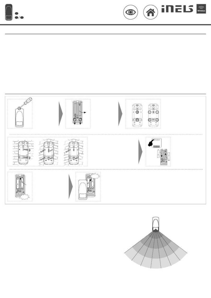
Assembly /
12
Push a screwdriver
into the opening
at the top of the
detector and open
the cover.
Push the beaks
(mouldings) of the
setting component
down and remove
the component
from
the base.
3Remove the mouldings from the base
(e.g. with a screwdriver) as required.
a) For placing on a flat surface.
b) For cornering.
4
Insert the programmed device
into the base and snap into
place with pressure, gently.
Check the correct location of
the batteries.
Replace and snap the
front cover.
5
6
+
-
AA
+
-
AA
AA
AA
Click!
• Position the detector at a height of up to 2.4 m. When assembling, allow manoeuvring space above
the detector (to replace the batteries, etc.).
• The detector is intended for indoor use.
• After inserting the battery, the time delay is 15 seconds to stabilize the PIR detector; it then activates
the motion detection function.
• When the detector is uncovered + 5 minutes after the cover is closed, activation is indicated by the
blinking of the blue LED and the inactivity after activation is shortened to 2 seconds (regardless of
the DIP2 setting). After this time, the idle time after activation is controlled by the DIP 2 setting and
the LED gives no indication.
* countersunk head, screw Ø 3 mm
0°
15°
30°
45° 60°
75°
90°
105°
12 m
9 m
6 m
3 m
Detection eld /
a) b)
Place the base at the desired location and
attach it with suitable bonding material*
according to the substrate.
a) On a flat surface.
b), c) in the corner.
a) b) c)
7
Click!
Assembly recommendations /
1/5
Program the instrument - see
Programming chapter.
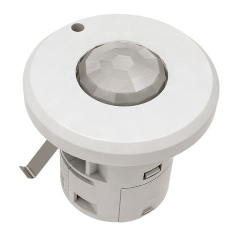
• The motion detector PIR is used to detect persons moving inside the building interior.
• Use:
- in combination with a switching unit for automatic control of lighting or triggering an alarm.
- by means of the Smart RF box, detection can be displayed on your smart phone in the form
of a notification; alarms are stored in the history, which is visualized in the application iHC.
• Sensitivity settings of the PIR detector for eliminating unwanted triggering.
• Integrated lighting sensor, thanks to which you can set the detector‘s reaction time.
• Option of activation / deactivation of the LED indicator on the detector cover.
• Anti-tamper function: an alarm is triggered if there is an unauthorized interference to the detec-
tor (disassembly), it sends a message.
• Power supply: battery 2x 1.5 V AA, the battery life is min. 1 year.
• “Low Battery” Alerts by double LED flashing or on iHC App.
• The detectors are compatible with switching components marked with the iNELS RF Control2
RFIO2communication protocol and the eLAN-RF system components.
• Communication frequency with bidirectional protocol iNELS RF Control2(RFIO2).
ELKO EP, s.r.o. | Palackého 493 | 769 01 Holešov, Všetuly | Česká republika | e-mail: [email protected]
EN Support: +420 778 427 366 | CZ Technická podpora: +420 775 444 609
Pohybový detektor
CZ
www.elkoep.com
Charakteristika
Montáž
Šroubovákem za-
tlačte do otvoru v
horní části detek-
toru a otevřete kryt
prvku.
Zobáčky (výlisky) u
nastavovacích prv-
ků stlačte směrem
dolů a vyjměte pří-
stroj ze základny.
Dle požadovaného umístění vylomte
výlisky ze základny (např. pomocí šrou-
bováku).
a) Pro umístění na rovnou plochu.
b) Pro umístění do rohu.
Naprogramovný přístroj vlož-
te do základny a mírným
tlakem zacvakněte. Překontro-
lujte správné umístění baterií.
Nasaďte a zacvakněte
přední kryt.
Přístroj naprogramujte - viz
kapitola Programování.
Základnu umístěte na požadované místo a
připevněte vhodným spojovacím materiá-
lem* dle podkladu.
a) na rovnou plochu.
b), c) do rohu.
Detekční poleDoporučení pro montáž
• Detektor umístěte do výšky max. 2.4 m. Při montáži počítejte s maniupulačním prostorem nad
detektorem (pro výměnu baterií apod.).
• Detektor je určen pro vnitřní použití.
• Po vložení baterie je časová prodleva 15 sekund pro stabilizaci PIR detektoru, poté se aktivuje funkce
detekce pohybu.
• Po dobu odkrytování detektoru + 5 minut po uzavření krytu je aktivace indikována bliknutím modré
LED a nečinnost po aktivaci je zkrácena na 2 sekundy (bez ohledu na nastavení DIP2). Po uplynutí
této doby se doba nečinnosti po aktivaci řídí nastavením DIPu 2 a LED neindikuje.
* vrut se zápustnou hlavou, Øvrutu 3 mm
• Pohybový detektor PIR slouží k detekci osob pohybujících se v interiéru.
• Použití:
- v kombinaci se spínacím prvkem pro automatickou regulaci osvětlení nebo spuštění sirény,
- prostřednictvím Chytré RF krabičky může být detekce zobrazována ve vašem chytrém te-
lefonu formou notifikace, přijaté alarmy jsou ukládány do historie, která je vizualizována v
aplikaci iHC.
• Nastavení citlivosti PIR detektoru pro eliminaci nežádoucích sepnutí.
• Integrovaný senzor osvětlení.
• Anti-sabotážní funkce: při neoprávněném zásahu do detektoru (demontáž) odesílá zprávu.
• Napájení: baterie 2x 1.5 V AA, životnost baterie min. 1 rok.
• Signalizace vybité baterie dvojitým probliknutím LED nebo formou aplikace iHC.
• Detektory jsou kompatibilní se spínacími prvky označenými komunikačním protokolem iNELS
RF Control2RFIO2a systémovými prvky eLAN-RF.
• Komunikace s protokolem iNELS RF Control2(RFIO2).

02-29/2017 Rev.2
RFMD-100
Motion detector
EN
Made in Czech Republic
ON
1 2 3
+
+
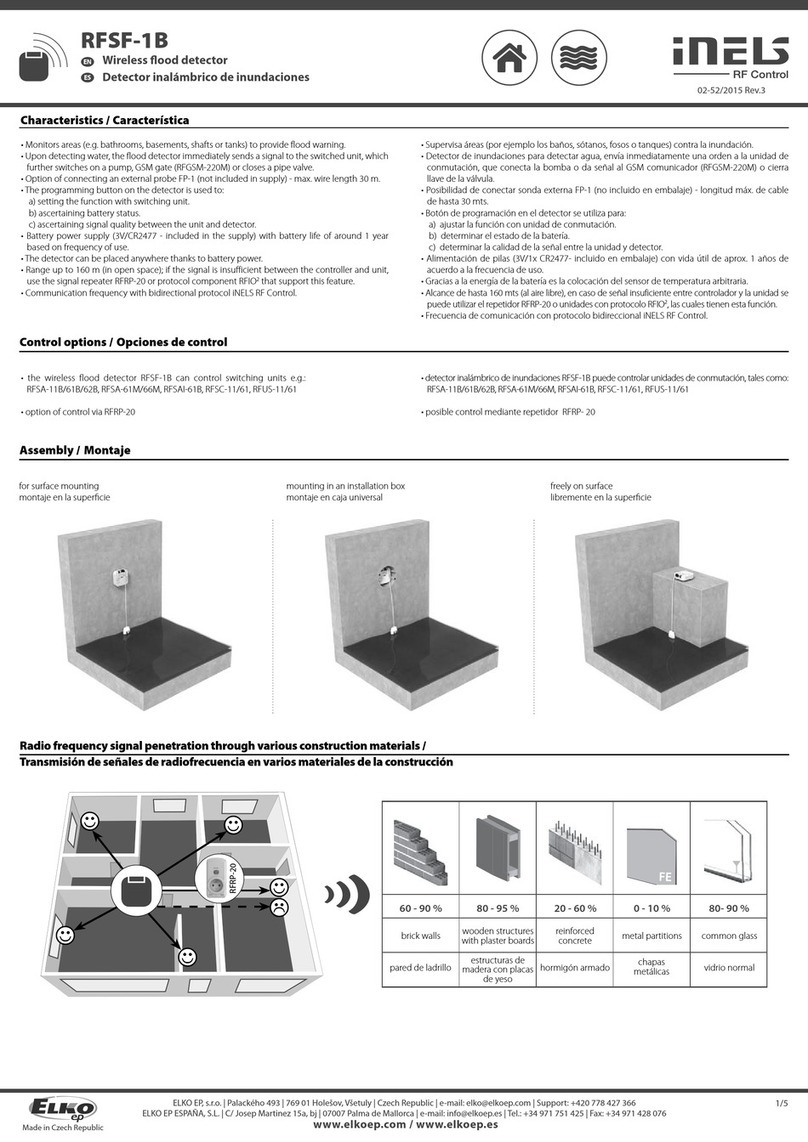
60 - 90 % 80 - 95 % 20 - 60 % 0 - 10 % 80- 90 %
brick walls wooden structures
with plaster boards reinforced concrete metal partitions common glass
Radio frequence signal penetration through various construction materials /
☺
☺
☺
☺
☺
RFRP-20
Indications, settings, functions /
Before starting to program, open the detector cover using a screwdriver.
Indicators and adjustment components are located inside the box.
• Blue LED - 1x blinks - indication when battery is inserted.
• Blue LED - 2x blinks - motion detection - low battery indication (if the detector is connected to a (eLAN,
RF Touch, iNELS) system, the battery level is indicated in the system).
TAMPER
SENS
LUX
motion sensor
LUX
SENS
ON
1 2 3
battery holders
DIP
LED
ON
1 2 3
+
+
+
-
AA
+
-
AA
1
Save the DIP switch settings /
Set the DIP switch (e.g. with a
screwdriver). Insert the batteries into the
battery holder in the detector.
Beware of polarity. The blue
LED on the detector will blink -
setting the DIP switch setting.
2
ON
1 2 3
+
+
2/5
• LUX adjustment component
- Adjustment of the level of response to the light intensity
• Setting the DIP switch
DIP1:
OFF - normal PIR sensor function
ON - light sensor function: when lighting is lower than the potentiometer setting, LUX
sends a command to activate the actuator (setting range is 0 - 500 Lx)
DIP2:
OFF - inactivity after 1 minute activation
ON - inactivity after activation for 5 minutes
DIP3:
OFF - The detector is paired with a compatible component - it does not periodically
send information about the current status
ON - The detector is connected to the system (eLAN, RF Touch, iNELS headquarters) - it
sends information in case of a change in status and periodically after 120 minutes.
• Any change to the DIP setting must be saved.
• SENS setting component
- PIR sensor sensitivity setting
• Settings can be made at any time.
ELKO EP, s.r.o. | Palackého 493 | 769 01 Holešov, Všetuly | Česká republika | e-mail: [email protected]
EN Support: +420 778 427 366 | CZ Technická podpora: +420 775 444 609
Pohybový detektor
CZ
www.elkoep.com
Indikace, nastavení, funkce
Prostup radiofrekvenčních signálů různými stavebními materiály
cihlové zdi dřevěné konstrukce
se sádrokart.
deskami
vyztužený beton kovové přepážky běžné sklo
Před zahájením programování otevřete pomocí šroubováku kryt detektoru.
Indikace a nastavovací prvky jsou umístěny uvnitř krabičky.
• Modrá LED - 1x blikne - indikace při vložení baterií.
• Modrá LED - 2x blikne při detekci pohybu - indikace slabé baterie (pokud je detektor připojen do systému
(eLAN, RF Touch, centrála iNELS), je slabá baterie indikována i v systému).
• Nastavovací prvek LUX
- nastavení rozhodovací úrovně pro reakci na intenzitu osvětlení
• Nastavení DIP přepínače
DIP1:
OFF - normální funkce PIR senzor
ON - funkce světelný senzor: při osvětlení nižším, než je nastavené na potenciometru
LUX posílá příkaz k aktivaci aktoru (rozsah nastavení je 0 - 500 Lx)
DIP2:
OFF - nečinnost po aktivaci 1 minuta
ON - nečinnost po aktivaci 5 minut
DIP3:
OFF - detektor je spárovaný s kompatibilním prvkem - neposílá periodicky informaci
o aktuálním stavu
ON - detektor je připojený do systému (eLAN, RF Touch, centrála iNELS) - posílá informaci
při změně stavu a také periodicky po 120 minutách.
• Každou změnu v nastavení DIPu je nutné uložit.
• Nastavovací prvek SENS
- nastavení citlivosti PIR čidla
• Nastavení lze provést kdykoliv.
snímač pohybu
držáky baterií
Uložení nastavení DIP přepínače
Nastavení DIP přepínače
(např. pomocí šroubováku).
Do držáku baterií v detektoru
zasuňte baterie. Pozor na po-
laritu. Modrá LED na detektoru
problikne - tím se nastavení DIP
přepínače uloží.

02-29/2017 Rev.2
RFMD-100
Motion detector
EN
Made in Czech Republic
Compatibility /
• control units
eLAN-RF-003, eLAN-RF-Wi-003
• switches
RFSA-61B, RFSA-62B, RFSAI-61B, RFSA-61M, RFSA-66M, RFSC-61, RFUS-61
• The detector can only be assigned to components marked with the iNELS RF
Control2RFIO2communication protocol.
ON
1 2 3
+
+
+
-
AA
+
-
AA
3
PROG < 1s
1 x
Functions and programming with compatible switches /
Function "Fixed-time delayed return" /
Description of the delayed return feature with xed time /
The output contact of the switching component switches on when the detector activates, it will
open for 1s.
Programming /
Press of programming button
on compatible actuator for
1 second will activate actuator
into programming mode. LED
is flashing in 1s interval.
Slide the battery into the battery
holder in the detector. Beware
of polarity. The blue LED on the
detector will blink. The LED on
a compatible component will
blink at a faster interval - thereby
assigning the detector to the
component.
Press of programming button
on compatible actuator
shorter then 1 second will
finish programming mode,
LED switches off.
2
1
PROG > 1s
1 x
Function "delayed return with time setting" /
Description of the delayed return function with time setting /
The output contact of the switching component switches on when the detector activates, it
opens after the set time interval has elapsed.
Programming /
Press of programming button
on compatible actuator for
1 second will activate actuator
into programming mode. LED
is flashing in 1s interval.
Slide the battery into the
battery holder in the detector.
Beware of polarity. The blue
LED on the detector will blink.
The LED on a compatible
component will blink at a faster
interval - thereby assigning the
detector to the component.
Remove one of the batteries
from the detector and insert
it back after 30 seconds. The
blue LED on the detector
will blink. The LED on a
compatible component will
blink at a faster interval.
1
PROG > 1s
1 x
ON
1 2 3
+
+
2
+
-
AA
+
-
AA
Remove the battery from the detector again. After
30 seconds, press the programming button for more than
5 seconds to bring the compatible component into timer
mode. LED 2x blinks at second intervals. When the button is
released, delayed return time is retrieved.
After setting the desired time (within 2s ...
60 min), the timer mode ends by inserting
the battery into the detector. The red LED
on the detector will blink. This saves the
time interval stored in the memory of the
component, the LED on the compatible
component blinks.
ON
1 2 3
+
+
3
+
-
AA
+
-
AA
30 s
ON
1 2 3
+
+
4
PROG > 5s
1 x
+
-
AA
+
-
AA
30 s
ON
1 2 3
+
+
t = 2s . . . 60min
5
+
-
AA
+
-
AA
3/5
ELKO EP, s.r.o. | Palackého 493 | 769 01 Holešov, Všetuly | Česká republika | e-mail: [email protected]
EN Support: +420 778 427 366 | CZ Technická podpora: +420 775 444 609
Pohybový detektor
CZ
www.elkoep.com
Kompatibilita
• systémové prvky
eLAN-RF-003, eLAN-RF-Wi-003
• spínače
RFSA-61B, RFSA-62B, RFSAI-61B, RFSA-61M, RFSA-66M, RFSC-61, RFUS-61
• Detektor lze přiřadit pouze k prvkům označeným komunikačním protokolem
iNELS RF Control2(RFIO2).
Stiskem programovacího tla-
čítka na kompatibilním prvku
na dobu 1 vteřiny se uvede
prvek do programovacího re-
žimu. LED bliká v intervalu 1
vteřiny.
Do držáku baterií v detektoru za-
suňte baterie. Pozor na polaritu.
Modrá LED na detektoru problik-
ne. LED na kompatibilním prvku
problikne v rychlejším intervalu
- tím se detektor k prvku přiřadí.
Stiskem programovacího tla-
čítka na kompatibilním prvku
na dobu kratší než 1 vteřina
se ukončí programovací režim,
LED zhasne.
Funkce a programování s kompatibilními spínači
Funkce "zpožděný návrat s pevným časem"
Výstupní kontakt spínacího prvku při aktivaci detektoru sepne, rozepne po 1s.
Programování
Popis funkce zpožděný návrat s pevným časem
Funkce "zpožděný návrat s nastavením času"
Popis funkce zpožděný návrat s nastavením času
Výstupní kontakt spínacího prvku při aktivaci detektoru sepne, rozepne po uplynutí nastaveného
časového intervalu.
Stiskem programovacího tla-
čítka na kompatibilním prvku
na dobu 1 vteřiny se uvede
prvek do programovacího re-
žimu. LED bliká v intervalu 1
vteřiny.
Do držáku baterií v detektoru
zasuňte baterie. Pozor na po-
laritu. Modrá LED na detektoru
problikne. LED na kompatibil-
ním prvku problikne v rychlej-
ším intervalu - tím se detektor
k prvku přiřadí.
Jednu z baterií z detektoru
vyjmout a po 30 vteřinách
vložit zpět. Modrá LED na
detektoru problikne. LED
na kompatibilním prvku pro-
blikne v rychlejším intervalu.
Baterii z detektoru opět vyjmout. Po 30 vteřinách stisk progra-
movací tlačítko na dobu delší než 5 vteřin uvede kompatibilní
prvek do časovacího režimu.
LED 2x problikne ve vteřinových intervalech. Po uvolnění tla-
čítka se začne načítat čas zpožděného návratu.
Po odčasování požadovaného času (v roz-
mezí 2s ... 60 min) se časovací režim ukončí
vložením baterie do detektoru. Modrá LED na
detektoru problikne. Tím se nastavený časový
interval uloží do paměti prvku, LED na kompa-
tibilním prvku problikne.
Programování
02-29/2017 Rev.2
RFMD-100
Motion detector
EN
Made in Czech Republic
When inserting the RFRP-20
into an electrical socket (upon
power-up), the programming
button must be pressed. The
green LED flashes. Then when
the red LED button illuminates,
release the button.
By one short press of the
programming button on
the RFRP-20, you move to the
position for input into
the additional learning mode.
The red LED flashes - after
5s the RFRP-20 enters the
additional learning mode. The
LED stops flashing.
2
PROG < 1s
1 x
1
End learning mode by a short
press of the programming
button on the RFRP-20. By
doing so, the programmed
address detector is stored
in the memory. The red LED
will flash for 1 second, then
the green LED will remain
illuminated.
4
PROG <1s
1 x
Insert the battery into the
battery holder in the detector
(beware of the polarity, the
blue LED on the detector will
blink). A flashing green LED on
the RFRP-20 indicates that the
RFMD-1 has been recorded in
the RFRP-20 memory.
3
ON
1 2 3
+
+
+
-
AA
+
-
AA
Programming with the RF control units /
address /
For the programming and communication of the detector with the
system components, the address shown on the underside of the
detector or in the left upper part of the open device is used.
xxxxxx
ON
1 2 3
+
+
+
-
AA
+
-
AA
XXXXXX
4/5
6
PROG < 1s
1 x
Press of programming button
on compatible actuator
shorter then 1 second will
finish programming mode,
LED switches off.
Detector communication through a repeater /
RFRP-20
You can set repeat functions for all components marked with iNELS RF Control2(RFIO2) using
the RFAF/USB service key.
RFAF/USB
ELKO EP, s.r.o. | Palackého 493 | 769 01 Holešov, Všetuly | Česká republika | e-mail: [email protected]
EN Support: +420 778 427 366 | CZ Technická podpora: +420 775 444 609
Pohybový detektor
CZ
www.elkoep.com
Stiskem program. tlačítka
na kompatibilním prvku na
dobu kratší než 1 vteřina se
ukončí programovací režim,
LED zhasne.
Programování s RF systémovými prvky
Pro programování a komunikaci detektoru se systémovými prvky slou-
ží adresa uvedená na spodní straně detektoru nebo v levé horní části
otevřeného přístroje.
Při zasunutí RFRP-20 do elek-
trické zásuvky (přivedení
napájení) musí být stisknuto
programovací tlačítko. Zelená
LED bliká. Poté co se rozsvítí
červená LED tlačítko uvolněte.
Jedním krátkým stiskem
programovacího tlačítka na
RFRP-20 se posunete na pozici
pro vstup do doučovacího re-
žimu. Červená LED bliká - po
5s RFRP-20 vstoupí do doučo-
vacího režimu. LED přestane
blikat.
Režim doučování ukončíte
krátkým stiskem program.
tlačítka na RFRP-20. Tím se
naprogramovaná adresa de-
tektoru uloží do paměti. Na
dobu 1s problikne červená
LED a poté se trvale rozsvítí
zelená LED.
Do držáku baterií v detektoru
zasuňte baterie (pozor na po-
laritu, modrá LED na detekto-
ru problikne). Tím se provede
odeslaní signálu. Probliknutí
zelené LED na RFRP-20 signa-
lizuje, že detektor byl zapsán
do paměti RFRP-20.
Komunikace detektoru přes reapeter
Funkci repeatru můžete nastavit u všech prvků označených logem iNELS RF Control2(RFIO2)
prostřednictvím servisního klíče RFAF/USB.
adresa

02-29/2017 Rev.2
RFMD-100
Motion detector
EN
Made in Czech Republic
Warning
Instruction manual is designated for mounting and also for user of the device. It is always a part of its packing. Instal-
lation and connection can be carried out only by a person with adequate professional qualification upon under-
standing this instruction manual and functions of the device, and while observing all valid regulations. Trouble-free
function of the device also depends on transportation, storing and handling. In case you notice any sign of damage,
deformation, malfunction or missing part, do not install this device and return it to its seller. It is necessary to treat
this product and its parts as electronic waste after its lifetime is terminated. Before starting installation, make sure
that all wires, connected parts or terminals are de-energized. While mounting and servicing observe safety regula-
tions, norms, directives and professional, and export regulations for working with electrical devices. Do not touch
parts of the device that are energized – life threat. Due to transmissivity of RF signal, observe correct location of
RF components in a building where the installation is taking place. RF Control is designated only for mounting in
interiors. Devices are not designated for installation into exteriors and humid spaces. The must not be installed into
metal switchboards and into plastic switchboards with metal door – transmissivity of RF signal is then impossible.
RF Control is not recommended for pulleys etc. – radiofrequency signal can be shielded by an obstruction, inter-
fered, battery of the transceiver can get flat etc. and thus disable remote control.
Technical parameters /
Attention:
When you instal iNELS RF Control system, you have to keep minimal distance 1 cm between
each units.
Between the individual commands must be an interval of at least 1s.
Power supply:
Battery life:
Drained battery indicator:
Transmission frequency:
Communication protocol:
Detection angle:
Detection distance:
Recommended working height:
Working temperature:
Protection:
Color:
Dimension:
Weight:
5/5
Replacement of a battery /
Push a screwdriver into the
opening at the top of the
detector and open the cover.
Remove the original battery
and insert new batteries into
the battery holder (never
mix old and new batteries).
Beware of the polarity.
The blue LED on the detector
will blink.
Replace and snap the front
cover.
1 2
ON
1 2 3
+
+
+
-
AA
+
-
AA
3
ON
1 2 3
+
+
+
-
AA
+
-
AA
Click!
When handling a device unboxed it is important to avoid contact with liquids. Never
place the device on the conductive pads or objects, avoid unnecessary contact with the
components of the device.
Safe handling /
ELKO EP, s.r.o. | Palackého 493 | 769 01 Holešov, Všetuly | Česká republika | e-mail: [email protected]
EN Support: +420 778 427 366 | CZ Technická podpora: +420 775 444 609
Pohybový detektor
CZ
www.elkoep.com
2x 1.5 baterry / baterie AA
min. 1 year, according to the number of activations /
min. 1 rok, dle počtu aktivací
yes / ano
866 MHz, 868 MHz, 916 MHz
iNELS RF Control2(RFIO2)
105°
max.12 m
max. 2.4 m
-10.. +50 °C
IP20
white / bílá
46 x 105 x 43 mm
57 g
Návod na použití je určen pro montáž a pro uživatele zařízení. Návod je vždy součástí balení. Instalaci a připojení
mohou provádět pouze pracovníci s příslušnou odbornou kvalifikací, při dodržení všech platných předpisů, kteří se
dokonale seznámili s tímto návodem a funkcí prvku. Bezproblémová funkce prvku je také závislá na předchozím
způsobu transportu, skladování a zacházení. Pokud objevíte jakékoliv známky poškození, deformace, nefunkčnosti
nebo chybějící díl tento prvek neinstalujte a reklamujte jej u prodejce. S prvkem či jeho částmi se musí po ukončení
životnosti zacházet jako s elektronickým odpadem. Před zahájením instalace se ujistěte, že všechny vodiče, připoje-
né díly či svorky jsou bez napětí. Při montáži a údržbě je nutné dodržovat bezpečnostní předpisy, normy, směrnice a
odborná ustanovení pro práci s elektrickými zařízeními. Nedotýkejte se částí prvku, které jsou pod napětím - nebez-
pečí ohrožení života. Z důvodu prostupnosti RF signálu dbejte na správné umístění RF prvků v budově, kde se bude
instalace provádět. RF Control je určen pouze pro montáž do vnitřních prostor. Prvky nejsou určeny pro instalaci do
venkovních a vlhkých prostor, nesmí být instalovány do kovových rozvaděčů a do plastových rozvaděčů s kovovými
dveřmi - znemožní se tím prostupnost radiofrekvenčního signálu. RF Control se nedoporučuje pro ovládání přístrojů
zajišťujících životní funkce nebo pro ovládání rizikových zařízení jako jsou např. čerpadla, el. topidla bez termostatu,
výtahy, kladkostroje ap. - radiofrekvenční přenos může být zastíněn překážkou, rušen, baterie vysílače může být
vybita ap. a tím může být dálkové ovládání znemožněno.
Varování
Technické parametry
Upozornění:
Při instalaci systému iNELS RF Control musí být dodržená minimální vzdálenost mezi jednotlivými
prvky 1 cm.
Mezi jednotlivými povely musí být rozestup minimálně 1s.
Napájení:
Životnost baterie:
Signalizace vybité baterie:
Vysílací frekvence:
Komunikační protokol:
Úhel detekce:
Detekční vzdálenost:
Doporučená pracovní výška:
Pracovní teplota:
Krytí:
Barva:
Rozměr:
Hmotnost:
Při manipulaci s přístrojem bez krabičky je důležité zabránit kontaktu s tekutinami. Přístroj
nikdy nepokládejte na vodivé podložky a předměty, nedotýkejte se zbytečně součástek
na přístroji.
Bezpečná manipulace s přístrojem
Šroubovákem zatlačte do ot-
voru v horní části detektoru a
otevřete kryt prvku.
Vyjměte původní baterie a do
držáku baterií zasuňte baterie
nové (nikdy nekombinujte
starou a novou baterii). Pozor
na polaritu.
Modrá LED na detektoru pro-
blikne.
Nasaďte a zacvakněte přední
kryt.
Výměna baterie
Table of contents
Other iNels Security Sensor manuals

iNels
iNels RF KEY-40 User manual

iNels
iNels RFSF-100 User manual

iNels
iNels RFWD-100 User manual

iNels
iNels RFSF-1B User manual

iNels
iNels RFSF-100 User manual

iNels
iNels DMD3-1 User manual

iNels
iNels RFSF-1B User manual

iNels
iNels RFSF-100 User manual

iNels
iNels RFMD-100 User manual

iNels
iNels RFSF-1B User manual
Popular Security Sensor manuals by other brands

B.E.G. LUXOMAT
B.E.G. LUXOMAT PD4-M-1C-GH-SM Installation and operating instruction

BEA
BEA IXIO-ST quick guide

Banner
Banner ES-UA-5A Instruction

Argus Security
Argus Security L-OP-SG Installation guides

B.E.G.
B.E.G. LUXOMAT Indoor 180-M-2C Installation and operating instruction

Takex
Takex MX-12FAMD instruction manual