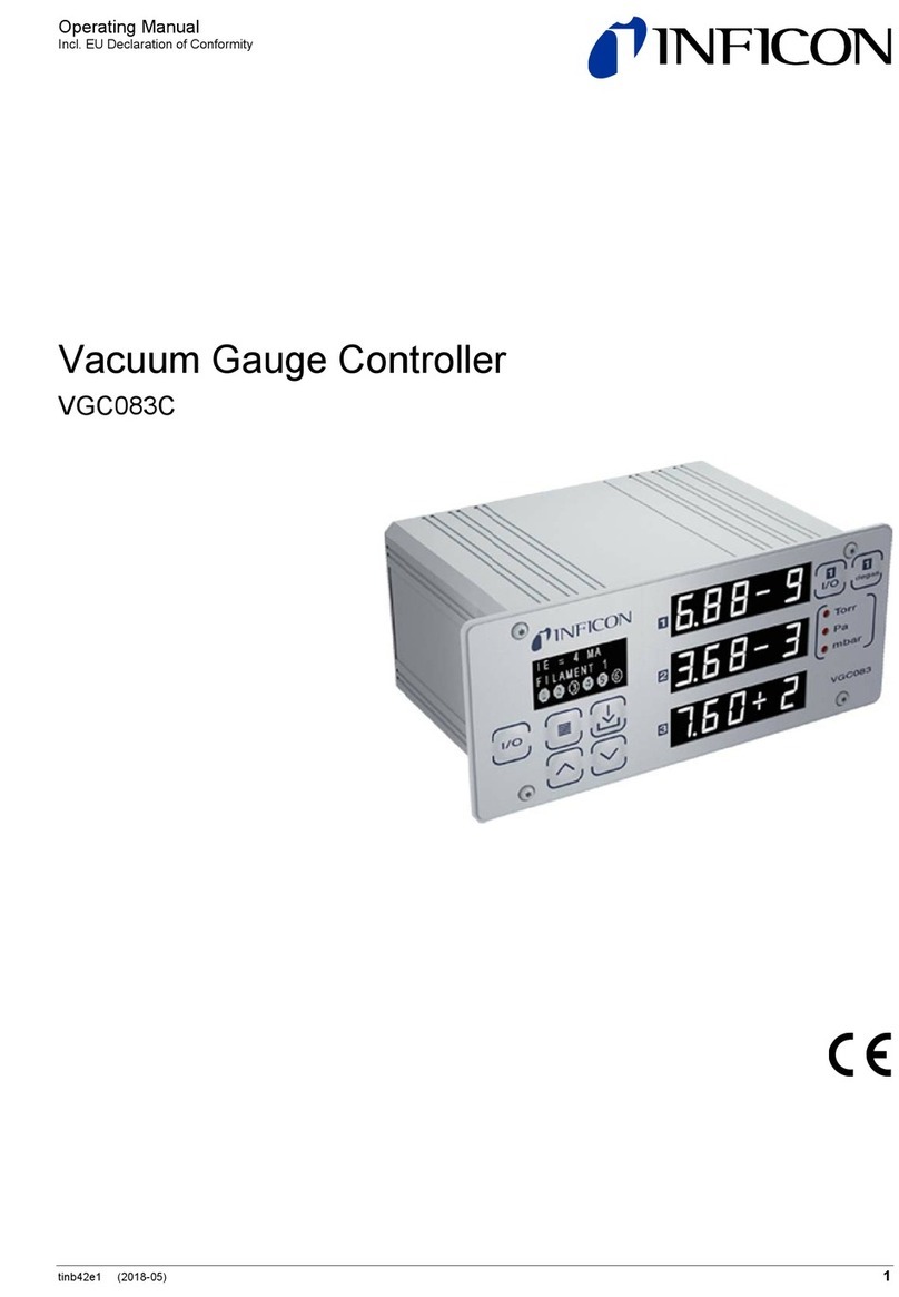
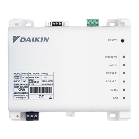
Inficon VGC083C User manual

Operating Manual
Incl. EU Declaration of Conformity
tinb42e1-a (2019-10) 1
Vacuum Gauge Controller
VGC083C

2tinb42e1-a (2019-10) VGC083C.om
In all communications with INFICON, please specify the information on the product
nameplate:
This document applies to products with part number 399-702.
The part number (PN) can be taken from the product nameplate.
We reserve the right to make technical changes without prior notice.
There are operational characteristic differences between solid state equipment and
electromechanical equipment. Because of these differences, and because there
are a variety of uses for solid state equipment, all persons that apply this equip-
ment must take every precaution and satisfy themselves that the intended appli-
cation of this equipment is safe and used in an acceptable manner.
In no event will INFICON be responsible or liable for indirect or consequential
damages that result from the use or application of this equipment.
Any examples or diagrams included in this manual are provided solely for illustra-
tive purposes. Because of the many variables and requirements imposed on any
particular installation, INFICON cannot assume responsibility or liability for any
actual use based on the examples and diagrams.
No patent liability is assumed by INFICON with respect to use of information cir-
cuits, equipment, or software described in this manual.
Throughout this manual we use notes, notices and apply internationally recognized
symbols and safety messages to make you aware of safety considerations.
Identifies information about practices or circumstances that can cause electrical or
physical hazards which, if precautions are not taken, could result in death or
serious injury, property damage, or economic loss.
Identifies information about practices or circumstances that can cause electrical or
physical hazards which, if precautions are not taken, could result in minor or
moderate injury, property damage, or economic loss.
Identifies information that is critical for successful application and understanding of
the product.
Product Identification
Validity
Important User Information
CAUTION
NOTICE

tinb42e1-a (2019-10) VGC083C.om 3
Labels may be located on or inside the device to alert people that dangerous
voltages may be present.
INFICON assumes no liability and the warranty is rendered null and void if the end-
user or third parties
•disregard the information in this document
•use the product in a non-conforming manner
•make any kind of interventions (modifications, alterations etc.) on the product
•use the product with accessories not listed in the corresponding product docu-
mentation.
Liability and Warranty
SHOCK HAZARD

4tinb42e1-a (2019-10) VGC083C.om
Contents
Product Identification 2
Validity 2
Important User Information 2
Liability and Warranty 3
1Introduction / General Information 6
1.1 Description 6
2Technical Data 7
2.1 VGC083C 7
2.2 Power Supply for VGC083C (Optional) 9
3Important Safety Information 10
3.1 Safety Precautions - General 10
3.2 Safety Precautions - Service and Operation 10
3.3 Electrical Conditions 11
3.3.1 Proper Equipment Grounding 11
3.3.2 Electrical Interface and Control 11
3.4 Overpressure and use with hazardous gases 11
3.5 Gases other than Nitrogen / air 12
4Installation 13
4.1 Mechanical Installation - Controller 13
4.1.1 Panel Mount 13
4.1.2 Rack Mount 13
4.1.3 Mechanical Installation - Ionization Gauge 14
4.1.4 Mechanical Installation - Convection Gauge 15
4.2 Electrical Installation 16
4.2.1 Grounding 16
4.2.2 Installation 16
4.2.3 Connecting MAG050 / MAG060 - connector labeled "1" 17
4.2.4 Connecting the PGE050 - connectors labeled "2" and "3" 17
4.2.5 Power Connection 18
4.2.6 Relay Connection 18
4.2.7 Analog Output Connection 18
4.2.8 Analog Input Connection (Capacitance Diaphragm Gauges, etc.) 18
4.2.9 Digital I/O Connection 19
4.2.10 RS232 / RS485 Serial Communications Connection 20
5Operation - IG and CG 22
5.1 IG Over Pressure Shut Down 22
5.2 Convection Gauge (CG) Initial Setup 22
5.3 Cond Cathode Activation Delay 23
6Setup and programming 24
6.1 Applying Power 24
6.2 Front Panel Display 24
6.3 User Interface Basics 25
6.4 Factory-Set Default Parameters 25
6.5 Programming 26
6.5.1 SETUP UNIT 27
6.5.2 ION GAUGE 28
6.5.3 CONVEC GAUGE 29
6.5.4 RELAYS 30
6.5.5 Analog Output 32
6.5.6 SERIAL COMM 36
6.5.7 DISPLAY 37
7Analog Output Charts & Equations (Nitrogen/Air Only) 39
7.1 Analog Output wide range measurement for IG - CG1 0.5 - 7V
(Nitrogen / Air only) 39
7.2 Analog Output for IG LOG N - 10 (Nitrogen / Air only) 40
7.3 Analog Output for IG LOG N - 11 (Nitrogen / Air only) 41
7.4 Analog Output for IG LOG N - 12 (Nitrogen / Air only) 42
7.5 Analog Output for IG 1.8 - 8.7 V (Nitrogen / Air only) 43
7.6 Analog Output for IG LINEAR (Nitrogen / Air only) 44
7.7 Analog Output for CG1 or CG2 1 - 8 V (Nitrogen / Air only) 44
7.8 Analog Output for CG1 or CG2 0 - 7 V (Nitrogen / Air only) 46
7.9 Analog Output for CG1 or CG2 NON - LIN (Nitrogen / Air only) 47
7.10 Analog Output for CG1 or CG2 LINEAR (Nitrogen / Air only) 49

tinb42e1-a (2019-10) VGC083C.om 5
8Using the Gauge with Different Gases 50
8.1 Ion Gauge Display Correction Factors for Selected Gases 50
8.2 Effects of Different Gases on Convection Gauge Display 51
8.3 Effects of Different Gases on Analog Output 55
8.3.1 Ion Gauge Analog Output Correction Factors for Selected Gases 55
8.3.2 IG - CG1 0.5 - 7V Analog Output Correction Factors for Selected Gases 55
8.3.2.1 IG-CG1 0.5 - 7V Analog Output Correction Factors -
Ion Gauge Range 56
8.3.2.2 IG-CG1 0.5 - 7V Analog Output Correction Factors -
Convection Gauge Range 57
8.3.3 Convection gauge analog output for selected gases 57
8.3.3.1 CG1 1 - 8 V or CG2 1 - 8 V Analog Output Correction Factors -
Convection Gauge 58
8.3.3.2 CG1 0 - 7 V or CG2 0 - 7 V Analog Output Correction Factors -
Convection Gauge 59
8.3.3.3 CG1 NON-LIN or CG2 NON-LIN Analog Output Correction Factors -
Convection Gauge 60
9Communication Protocol (Serial Interface) 61
9.1 Device Specific Serial Communication Info 61
9.2 INFICON RS232 / RS485 Command Protocol Summary 61
9.3 INFICON RS232 and RS485 Command Protocol Summary 62
9.4 RS232 GP 307 and 358 Protocol 65
9.5 RS485 GP 307 and 358 Protocol 66
10 Service 68
10.1 Calibration 68
10.2 Maintenance 68
10.3 Troubleshooting - Operation 68
10.4 Troubleshooting - Error Messages 69
10.5 Clearing Error Messages 69
10.6 Research Screen 69
10.6.1 Research Screen (Diagnostic Display) 69
10.7 Cleaning the VGC083C 70
11 Repair 70
12 Accessories 70
13 Storage 71
14 Disposal 71
EU Declaration of Conformity 72
For cross-references within this document, the symbol (→XY) is used; for cross-
references to further documents listed under ‘Literature’, use is made of the symbol
(→[Z]).

6tinb42e1-a (2019-10) VGC083C.om
1 Introduction / General Information
The Vacuum Gauge Controller VGC083C is a vacuum pressure measurement
system which is comprised of the following:
•The VGC083C Vacuum Gauge Controller
•One INFICON MAG050 or MAG060 passive Cold Cathode Gauge head
•One or two INFICON PGE050 convection enhanced pirani heads1)
•Cables to interconnect the VGC083C and point-of-use devices
1) The VGC083C will also operate the Granville-Phillips®Convectron®convection enhanced pirani
vacuum gauge head.
Typical components of the complete vacuum measurement system are shown in
the figure below. The VGC083C provides power and operating control for the
MAG050 / 060 hot ion gauge head (IG). Additionally, it provides power and
operating control for up to two enhanced convection gauges (CG).
VGC083C Vacuum Gauge
Controller
MAG050 or MAG060
passive Cold Cathode Gauge
head
PGE050 Convection Gauges
1 & 2 (CVG 1 & 2)
The VGC083C, a controller unit capable of controlling multiple gauge heads, is
either rack or instrument panel mountable. Optional industry standard 19-inch, 2U
high rack-mount panels are available to mount the unit into rack enclosures. For
important information about the PGE050 convection gauge, MAG050 / MAG060
passive Cold Cathode Gauge heads please refer to the Operating Manual for each
of this products. Read the Operating Manuals in their entirety for any device you
intend to connect to the VGC083C prior to connecting and using the external
devices and cables that the VGC083C is intended to be used with.
1.1 Description
Typical Components of the
complete Vacuum Pressure
Measurement System

tinb42e1-a (2019-10) VGC083C.om 7
2 Technical Data
VGC083C
with MAG050 & PGE050
with MAG060 & PGE050
1.5×10⁻⁹ … 1000 Torr
7.5×10
-11
… 1000 Torr
Units of measurement
Torr, mbar, Pa (user selectable)
Pressure indication LED - 3 independent pressure display
channels, 3 digit plus 2 digit exponent per
channel
Programming & set-up screen OLED - displays state of all setpoint relays, IG
emission current, error messages for fault
conditions
IG powers & operates one INFICON MAG050 or
MAG060 passive Cold Cathode Gauge
CG , powers & operates up to 2 INFICON PGE050
convection or Granville-Phillips®(GP)
Convectron
®
Alternate gauge displays pressure from an alternate gauge such
as a Capacitance Diaphragm Gauge - CDG or
other INFICON gauges using the analog input
(external power source for these alternate
auxiliary devices will be required)
IG sensor on/off can all be controlled via front panel soft-keys, remote input signals
(digital I/O) or serial communications. IG sensor can also be automatically turned
on/off using measurements from one of the user selectable convection or alternate
gauges.
IG sensor on/off can also be set by applying momentary continuity to ground. Also
the 9-pin D-sub remote input DIGITAL I/O connector provides pin-pin compatible
signals with the GP 358 controller as well as compatible signals with the GP 307.
Number 6
single-pole, double-throw (SPDT), user as-
signable to any of the gauges
Contact rating 5 A at 30 V (dc), 5 A at 250 V (ac), resistive
load
2.1 VGC083C
Measurement range
Display
Functionality
IG sensor control
IG remote input signals
(digital I/O)
Setpoint relays

8tinb42e1-a (2019-10) VGC083C.om
IG analog output
Log-linear
0 … 10 V (dc), 1 V/decade, or 1)
1.7 … 9.3 V (dc) (nominal 1.8 … 8.7 V (dc)),
0.8 V/decade
Linear
0 … 10 V (dc) (useable over 3 decades) 2)
Combination IG + CG or
IG + ALT analog
Log-linear
0.5 … 7 V (dc), 0.5 V/decade
CG analog output
Log-linear
1 … 8 V (dc), 1 V/decade 3), or
0 … 7 V (dc), 1 V/decade
3)
Linear
0 … 10 V (dc) (useable over 3 decades)
Non-linear analog S-curve
0.375 … 5.659 V (dc)
1) Various scaling selections also provide output compatibility with Granville-Phillips®
controller models 307, 350 and 358 controllers.
2) Also compatible with GP 307 controller.
3) Also compatible with GP 307, 350 and 358.
CDG one 0 … 10 V (dc) analog input signal from a
CDG when used as an alternate gauge to CG2
INFICON analog input from one of the following gauges:
PGE300, PGE500, BAG302
Protocol RS485 / RS232 - ASCII protocol
(command protocol compatibility with GP 307
and GP 358 controller is also provided)
IG sensor on/off status displayed as pressure reading on the front panel, by serial
communications and by SPDT relay (DIGITAL I/O Connector) rated at 1 A at
30 V (dc) resistive, or 1 A at 30 V (ac) non-inductive.
IG error conditions are displayed on the front panel, by serial communications and
by an open collector transistor output (ground emitter) rated at 40 V max. VCE,
50 mA IC max.
Turns ion gauge off at 5.00 × 10⁻³ or overpressure value programmed by the user.
Temperature
Operation
Storage
0 … +40 °C
–40 … +70 °C
Relative humidity
0 … 95, non-condensing
Altitude
Operating
Storage
max. 2500 m (8200 ft.)
max. 12500 m (41000 ft.)
Housing
aluminum extrusion
Analog output
Analog input
Serial communications
Status output
IG overpressure protection
Ambience
Housing

tinb42e1-a (2019-10) VGC083C.om 9
Voltage 20 … 28 V (dc), 12 W
protected against power reversal and transient
over-voltages
Connectors
IG & CG
Digital I/O
Serial communications
RS232
RS485
analog I/O, setpoint relays,
power
gauge cable assemblies provided by INFICON
9-pin D-sub male
9-pin D-sub female
9-pin D-sub male
pluggable terminal block (mating connectors
included)
mm (inch)
0.7 kg (1.7 lb.)
Connector 2-pin pluggable terminal block to mate with the
VGC083C
Power input
100 … 240 V (ac), 50 … 60 Hz
Power output
24 V (dc), 2.5 A (60 W)
Compliance
CE, RoHS, UL (US/Canada), CCC (China)
Mains specifications
Dimensions
Weight
2.2 Power Supply for
VGC083C (Optional)

10 tinb42e1-a (2019-10) VGC083C.om
3 Important Safety Information
INFICON has designed and tested this product to provide safe and reliable service,
provided it is installed and operated within the strict safety guidelines provided in
this manual. Please read and follow all warnings and instructions.
To avoid serious injury or death, follow the safety information in this docu-
ment. Failure to comply with these safety procedures could result in serious
bodily harm, including death, and or property damage.
Failure to comply with these warnings violates the safety standards of installation
and intended use of this instrument. INFICON disclaims all liability for the cus-
tomer's failure to comply with these instructions.
Although every attempt has been made to consider most possible installations,
INFICON cannot anticipate every contingency that arises from various installations,
operation, or maintenance of the instrument. If you have any questions about the
safe installation and use of this product, please contact INFICON.
This device meets FCC part 15 requirements for an unintentional radiator, class A.
Hazardous voltages are present with this product during normal operation. The
product should never be operated with the covers removed unless equivalent pro-
tection of the operator from accidental contact with hazardous internal voltages is
provided.
WARNING! There are no operator serviceable parts or adjustments inside
the product enclosure. Refer servicing to service trained personnel.
Do not modify this product or substitute any parts without authorization of qualified
INFICON service trained personnel. Return the product to an INFICON qualified
service and repair center to ensure that all safety features are maintained. Do not
use this product if unauthorized modifications have been made.
WARNING! Source power must be removed from the product prior to
performing any servicing.
After servicing this product, ensure that all safety checks are made by a qualified
service person. When replacement parts are required, ensure that the parts are
specified by INFICON. Substitutions of non-qualified parts may result in fire, elec-
tric shock or other hazards. Use of unauthorized parts or modifications made to this
product will void the warranty.
To reduce the risk of fire or electric shock, do not expose this product to rain or
moisture. These products are not waterproof and careful attention must be paid to
not spill any type of liquid onto these products. Do not use these products if they
have been damaged. Immediately contact INFICON to arrange return of the pro-
duct if it is damaged.
Due to the possibility of corrosion when used in certain environmental conditions, it
is possible that the product’s safety could be compromised over time. It is important
that the product be periodically inspected for sound electrical connections and
equipment grounding. Do not use if the equipment grounding or electrical insulation
has been compromised.
Ensure the enclosure of the unit is connected directly to a good quality earth
ground.
Ensure that the vacuum port on which the vacuum gauge sensors are mounted is
electrically grounded.
Use a power source of 20 … 28 V (dc), 12 W or use INFIOCN series optional
power supplies.
Turn off power to the unit before attempting to service the controller.
3.1 Safety Precautions -
General
3.2 Safety Precautions -
Service and Operation
WARNING

tinb42e1-a (2019-10) VGC083C.om 11
Turn off power to the unit if a cable or plug is damaged or the product is not operat-
ing normally according to this instruction manual. Contact qualified INFICON ser-
vice personnel for any service or troubleshooting condition that may not be covered
by this operating manual.
It is important that the product be periodically inspected for sound electrical con-
nections and equipment grounding. Do not use if the equipment grounding or
electrical insulation has been compromised.
Do not use if the unit has been dropped or the enclosure has been damaged.
Contact INFICON for return authorization and instructions for returning the product
to INFICON for evaluation.
If measured pressure exceeds 5.00 × 10⁻³ Torr or the value programmed in the
“OVER PRESSURE” menu the sensor will turn off.
WARNING! When high voltage is present in any vacuum system, a life threat-
ening electrical shock hazard may exist unless all exposed electrical conductors
are maintained at earth ground potential. This applies to all products that come in
contact with the gas contained in vacuum chambers. An electrical discharge within
a gaseous environment may couple dangerous high voltage directly to any un-
grounded conductor of electricity. A person could be seriously injured or killed by
coming in contact with an exposed, ungrounded electrical conductor at high vol-
tage potential. This condition applies to all products that may come in contact with
the gas inside the vacuum chamber (vacuum/pressure containment vessel).
WARNING! Hazardous voltages that could seriously injure or cause death are
present in many vacuum processes. Verify that the vacuum connection ports on
which the ion gauge and the convection gauges are mounted are electrically
grounded. Consult a qualified Electrician if you are in doubt about your equipment
grounding. Proper grounding of your equipment is essential for safety as well as
intended operation of the equipment. The vacuum gauge heads and enclosure of
any control module must be connected directly to a good quality equipment
earthing conductor. Use a ground lug on the vacuum connection flange of the
pressure measurement devices if necessary.
WARNING! In order to protect personnel from electric shock and bodily
harm, shield all conductors which are subject to potential high voltage elec-
trical discharges in or around the vacuum system.
It is the user’s responsibility to ensure that the electrical signals from this product
and any connections made to external devices, for example, relays and solenoids,
are used in a safe manner. Always double check the system set-up before using
any signals to automate your process. Perform a hazardous operation analysis of
your system design and ensure safeguards and personnel safety measures are
taken to prevent injury and property damage.
WARNING! Install suitable protective devices that will limit the level of
pressure inside your vacuum chamber to less than what the vacuum chamber
system components are capable of withstanding.
In cases where an equipment failure could cause a hazardous condition, always
implement fail-safe system operation. For example, use a pressure relief device in
an automatic backfill operation where a malfunction could result in high internal
pressures if the pressure relief device was not installed on the chamber.
The vacuum gauge heads used with this product are not intended for use at
pressures above 20 psia (1000 Torr); DO NOT exceed 35 psig (< 2 ½ bars) pres-
sure inside the sensor. The MAG050 / 060 passive cold cathode vacuum gauge
heads have an admissible pressure of 130 psi (9 bar absolute - limited to inert
gases <55 °C). If your chamber goes to higher pressures than what these heads
are rated for, you should install an isolation valve or pressure relief device to pro-
tect the gauge tube from overpressure conditions. With some fittings, actual safe
overpressure conditions may be lower; for example, a quick-connect, O-ring com-
pression fitting may forcibly release the gauge tube from the vacuum chamber
fitting with only a few psi over local uncorrected barometric (atmospheric) pressure.
3.3 Electrical Conditions
3.3.1 Proper Equipment
Grounding
3.3.2 Electrical Interface and
Control
3.4 Overpressure and use
with hazardous gases

12 tinb42e1-a (2019-10) VGC083C.om
CAUTION! If the internal pressure of a vacuum gauge device is allowed
to increase above local uncorrected barometric pressure (atmospheric pres-
sure side), vacuum fittings may release and possible overpressure conditions
may cause leaks that would allow the gas inside the gauge tube to release
into the atmosphere of the surrounding environment. Toxic, pyrophoric and
flammable gases are examples of hazardous gases that if allowed to leak out
of the vacuum/pressure containment vessel into the atmospheric environ-
ment, could cause bodily injury and possible damage to equipment. Never
expose the gauge tube internal volume to pressure above local atmospheric
pressure when using hazardous gases.
WARNING! Do not attempt to use with gases other than nitrogen (N2) or air
without referring to correction factor data tables.
INFICON gauges and modules are calibrated for direct readout of nitrogen or air.
Do not attempt to use with other gases such as argon (Ar) or carbon dioxide (CO2)
unless you have applied correction factors to both the displayed pressure and the
analog output to determine the true measured pressure. This is particularly critical
when using convection gauges to measure pressure of gases other than N2/Air.
WARNING! Do not use the PGE050 in an explosive atmosphere or in the pre-
sence of flammable gases, vapors or fumes. Do not use the PGE050 to measure
the pressure of explosive or combustible gases or gas mixtures. The sensor wire in
the gauge normally operates at 125 °C, but if malfunction should occur, the wire
temperature could exceed the ignition temperature of certain combustible gases
and gas mixture. This could cause an explosion which could result in serious injury
or death.
3.5 Gases other than
Nitrogen / air

tinb42e1-a (2019-10) VGC083C.om 13
4 Installation
The unit is intended for indoor use only. The unit is offered as a space saving half
rack design. It may also be used as a bench top device or easily installed in an
instrument panel. Optional EIA-standard rack mount panels are available for either
full rack or dual, side-by-side rack mount installation.
Make a cutout in your rack panel or instrument control panel as shown in
the drawing below. Be sure to allow clearance behind the panel for the in-
strument as well as connectors and cables at the back of the instrument.
Optional EIA-standard, 19-inch, 2U height rack mount panels are available
from INFICON. The optional rack mount panels are provided with panel cut-
outs and mounting holes to allow efficient mounting of your VGC083C unit.
Drill four guide holes on each side of the panel cut out (two on each side)
with dimensions as shown in the panel cut-out drawing above.
Slide the unit into the panel hole cut-out. Guide the four studs on the back of
the unit front panel face plate thru the four holes next to the panel cut-out.
Use four # 10-32 Hex Nut (provided with instrument) to tighten the unit to
the panel.
Optional EIA-standard 19-inch wide, 2U height rack mount panels available from
INFICON (→70):
4.1 Mechanical Installation -
Controller
4.1.1 Panel Mount
Procedure
4.1.2 Rack Mount

14 tinb42e1-a (2019-10) VGC083C.om
All dimensions in inches.
All dimensions in inches.
The single cut-out and dual cut-out rack mountable panels shown above are availa-
ble from INFICON. Panel color matches the front panel of VGC083C units. Screws
for mounting to rack enclosure are included.
For more detailed information about the MAG050 / 060 cold cathode
ionization gauge, please refer to the Operating Manual for this product.
CAUTION! Dirt and damage can impair the function of the vacuum compo-
nent. Take appropriate measures to ensure cleanliness and prevent damage.
Touching the product or parts with bare hands increases the desorption rate.
Always use clean, lint free gloves as well as clean tools when working with this
product.
Mount the ionization gauge as close as possible to the pressure you want to meas-
ure. Long or restricted, small diameter tubing will create a pressure difference bet-
ween your process chamber and the gauge. This may cause a delay in response to
pressure changes. Mounting the ionization gauge too close to a gas source inlet
may also cause measurement and control instability.
The gauge can be mounted in any orientation, however, if possible, mount the
gauge with port down to help minimize the effect of any particles or condensation
collecting in the gauge.
Do not mount the gauge where it will be subjected to excessive vibration.
Vibrations may cause unstable readings, measurement errors and possible me-
chanical stress to components in the gauge.
For electrical safety purposes the housing of the gauge must be grounded to the
vacuum chamber. When using KF flanges, metal clamps must be used to ensure
proper grounding. If the gauge may come into contact with charged particles
(plasma, ion beam etc.), make sure its vacuum connections is galvanically con-
nected to the vacuum chamber and do always use conductive metallic centering
rings and clamps. Do not attempt to modify your flange in order to use non-metal-
lic-type flange clamps.
Single cut-out panel
Single cut-out panel
4.1.3 Mechanical Installation -
Ionization Gauge

tinb42e1-a (2019-10) VGC083C.om 15
Use all metal vacuum fittings with metal seals when operating pressures are ex-
pected to be below 1.00 × 10⁻⁷ Torr (1.33 × 10⁻⁷ mbar, 1.33 × 10⁻⁵ Pa).
Remove the protective lid and install the product to the vacuum system following
manufacturer's recommendations for different flanges and fittings. Keep the protec-
tive lid for future maintenance.
For more detailed information about the PEG050 convection gauge,
please refer to the Operating Manual for this product.
Mount the PGE050 as close as possible to the pressure you want to measure.
Long or restricted, small diameter tubing will create a pressure difference between
your process chamber and the gauge. This may cause a delay in response to
pressure changes.
Mounting the PGE050 too close to a gas source inlet may also cause
measurement and control instability. Do not mount the PGE050 near a source of
heating or cooling, such as heaters or air conditioning vents.
Mount the PGE050 with its main axis horizontal (see diagram below). Pressure
reading errors may occur above 1 Torr if the unit is not mounted horizontally. Below
1 Torr, mounting position has little to no effect.
Mount the PGE050 with port down, if possible, to help minimize the effect of any
particles or condensation from collecting in the gauge.
Do not mount the PGE050 where it will be subjected to excessive vibration. Vibra-
tions may cause unstable readings, measurement errors and possible mechanical
stress to components in the PGE050.
Flanges/ Fittings - follow the manufacturer's recommendations and note the
following:
- NPT fittings: When connecting the device using a NPT fitting, apply a thread seal-
ant compound or wrap the threaded portion of the tubing with one-and-a-half to two
wraps of pipe thread seal tape such as PTFE (Teflon®) tape and hand tighten the
gauge into the gauge port. Do not use a wrench or other tool which may damage
the gauge.
4.1.4 Mechanical Installation -
Convection Gauge

16 tinb42e1-a (2019-10) VGC083C.om
Be sure the vacuum gauges and the rest of your vacuum system are properly
grounded to protect personnel from shock and injury. Be aware that some vacuum
fittings, especially those with O-rings when not used with metal clamps, may not
produce a good electrical connection between the gauge and the chamber it is
connected to. Use a ground lug on the vacuum connection flange of the pressure
measurement device if necessary. The VGC083C control unit should be connected
to earth ground via a good quality equipment earthing conductor. It is encouraged
that you connect a separate 12-AWG earthing conductor between a known facility
earth ground connection and the location marked with the earth ground symbol (via
the green colored screw provided) on the back panel of the VGC083C.
A good, recommended practice is to remove power from any cable prior to con-
necting or disconnecting it. The electrical connections for the VGC083C are located
on the back panel of the device as shown below.
4.2 Electrical Installation
4.2.1 Grounding
4.2.2 Installation

tinb42e1-a (2019-10) VGC083C.om 17
CAUTION! It is always good industry practice to turn off power to the instru-
ment before connecting or disconnecting cables.
The custom cable / connector assembly are custom cable assemblies provided in
different lengths from INFICON for connecting the VGC083C to the MAG050 / 060
cold cathode ionization gauge sensor.
Changing cables from one device to another when power is applied is not only bad
electronics handling procedure, it is not advised and, if done by the user of this
equipment, may lead to erroneous measurement results, a hazardous situation,
equipment damage and possible operator injury.
Part numbers →70.
MAG050 / MAG060 IG
bakable cable 250 °C
MAG050 / MAG060 IG
80 °C
PN 399-580 … -582 are a custom cable assemblies provided in different lengths
from INFICON for connecting the VGC083C to INFICON PGE050 gauge or MKS
Instruments / Granville-Phillips®275 Convectron®vacuum gauge sensor. Connect
the DE-9 D-subminiature connector to VGC083C and PGE050 connectors to "2" or
"3".
For your reference, the wiring chart for the PGE050 cable provided by INFICON is
shown below. In addition to INFICON provided standard cable assembly lengths,
INFICON will provide custom length cable assemblies upon request.
VGC083C
pin no.
connects to PGE050 gauge pin no.
(INFICON molded, custom connector)
1
⇒
n.c.
2
⇒
cable shield
3
⇒
3
4
⇒
3
5
⇒
2
6
⇒
5
7
⇒
1
8
⇒
1
9
⇒
n.c.
4.2.3 Connecting MAG050 /
MAG060 - connector
labeled "1"
4.2.4 Connecting the PGE050 -
connectors labeled "2"
and "3"

18 tinb42e1-a (2019-10) VGC083C.om
The VGC083C requires an input power of 20 … 28 V (dc), 12 W to operate. One
each 2-contact pluggable terminal strip mating connector is provided for connection
to the power contactors. Optional power supplies are also available from INFICON
(PN →70).
Power
(contacts)
Contact Description Power Input
Connector
+
Power input (20 … 28 V (dc), 12 W)
– Power ground
A total of six setpoint relays are provided by the VGC083C. Two each 9-contact
pluggable terminal strip mating connectors are provided for easy connection to the
relay contactors. The VGC083C back panel relay connectors are marked RLY1
thru RLY6. Each relay has a contact labeled = (Normally Open), ≠(Normally
Closed) and I(common).
RLY1 thru RLY6
(contacts)
Contact Description Relay Connectors
= Relay #1 to Relay #6
(NORMALY OPEN)
≠Relay #1 to Relay #6
(NORMALLY CLOSED)
I Relay #1 to Relay #6 (COMMON)
A total of three analog outputs are provided by the VGC083C. These output volt-
age signals are proportional to the displayed pressure for any of the user assigned
vacuum gauges. Three each 2-contact pluggable terminal strip mating connectors
are provided for connection to the analog output contactors. The VGC083C back
panel analog output connectors are marked AO1, AO2 and AO3. Each connector
has a contact labeled +(analog output signal) and –(analog output ground).
AO1 , AO2, AO3
(contacts)
Contact Description Analog Output
Connectors
+
Analog Output #1 to #3 (Signal)
– Analog Output Ground #1 to #3
(Signal Return)
One analog input is provided by the VGC083C for using as an alternate gauge to
"2". This input can be accepted from one capacitance diaphragm gauge or other
INFICON vacuum module series PGE300, PGE500 or BAG302. One each 3-con-
tact mating pluggable terminal strip connector is provided for connection to the
analog input contactor. The VGC083C back panel analog input connector is
marked A1. Each connector has a contact labeled +(analog input signal) and –
(analog input ground) and D(power detect).
A1
(contacts)
Contact Description Analog Input
Connector
+
Analog Input (Signal)
–
Analog Input Ground (Signal Return)
D Detect (power detect)
4.2.5 Power Connection
4.2.6 Relay Connection
4.2.7 Analog Output
Connection
4.2.8 Analog Input Connection
(Capacitance Diaphragm
Gauges, etc.)

tinb42e1-a (2019-10) VGC083C.om 19
When using a capacitance manometer / diaphragm gauge or INFICON modules
such as the PGE300, PGE500, BAG302 as an ALTERNATE GAUGE, the gauge
must be connected to the VGC083C as shown below. The alternate gauge must be
provided power from an auxiliary power supply capable of providing the power re-
quired by the alternate gauge connected to the VGC083C. The D contact is used in
this configuration to protect the IG from being turned on at high pressure in case
power to the alternate gauge is lost.
The IG can be controlled manually using the front panel soft-keys, via remote input
signals using the digital I/O connector or RS232/RS485 commands. The VCG083C
can also be configured so that the IG sensor on/off is controlled by using the
pressure measurements from CG1 , CG2 or the alternate gauge. If the user
prefers digital I/O as the means of controlling the IG , various control input and
status output signals are available from the 9-pin D-sub male DIGITAL I/O con-
nector. The DIGITAL I/O Connector also provides pin-pin compatible signals with
the GP 358 vacuum gauge controller as well as compatible signals with the
GP 307.
The DIGITAL I/O Connector provides three different types of signals as listed
below:
The IG sensor on/off can be set by applying momentary continuity to ground.
This requires a momentary ground of less than 0.4 V (dc) at 10 µA for 25 msec
(minimum) be applied. After this, the input must be allowed to float higher than
3.5 V (dc) for 105 msec (minimum) before another low can be applied.
Input signal: Apply momentary continuity to ground to turn IG sensor on or off
The IG on/off status relay is also available as both normally open and normally
closed to indicate IG is on or off. This is an output signal to other external instru-
ments to confirm IG filament is on or off. The IG on / off status relay is a single
pole, double-throw (SPDT) relay rated at 1.0 A, 30 V (dc) resistive or 1.0 A,
30 V (ac) non-inductive.
This can be used as an output signal to other external instruments to confirm
whether any error conditions exist.
Signal: Open collector transistor (ground emitter) rated at 40 V max. VCE,
50 mA IC max.
Transistor on = error condition exists,
Transistor off = no error condition exists
4.2.9 Digital I/O Connection
Signal Type A - Control Input
Signals
Signal Type B - Status Output
Signal
Signal Type C - Error output
Signal

20 tinb42e1-a (2019-10) VGC083C.om
9-pin (DE-9P) D-subminiature DIGITAL I/0 Connections
Pin
no.
Description Signal
Type
Digital I/O
Connector
1
IG Sensor on/off
A
2
Ground
3
n.a.
A
4
IG on/off Status relay common
B
5 IG on/off status relay - Normally Closed
Relay open = IG on
B
6
n.a.
A
7
Ground
8
Error status, Low = error exists
C
9 IG on/off status relay - Normally open
Relay closed = IG on
B
Either RS232 or RS485 serial communications may be used to send / receive com-
mands to / from the VGC083C. There are two DE9 (D-subminiature, shell size E,
9 pole) connectors that allow independent cable connections to the RS232 and
RS485 serial communication ports. Six serial communication protocols are sup-
ported.
1. RS485 with address, start and stop characters and command / response syntax
derived from the INFICON BAG302 IG protocol.
2. RS232 with start and stop characters, but no addressing is used. The syntax is
the same as the RS485 protocol.
3. RS232 protocol compatible with the Granville-Phillips Series 307 and 358
controllers.
4. RS485 protocol compatible with the Granville-Phillips Series 307 and 358
controllers.
The RS232 serial port is configured to allow, for example, a 9-pin extension cable,
male to female, wired "pin-to- pin" to be connected from the VGC083C to your
serial port. DO NOT connect both of the RS232 and RS485 cables to the
VGC083C at the same time. The VGC083C cannot provide both RS232 and
RS485 serial communications at the same time. Only one or the other as pro-
grammed by the user.
An extension cable wired pin-to-pin
may be used to connect the RS232
serial port on the VGC083C directly to
your PC serial port (a converter may be
necessary).
DE-9 Connectors for connections to
user supplied cables for serial
communication port – DE9P (RS485),
DE9S (RS232)
4.2.10 RS232 / RS485 Serial
Communications
Connection
Other manuals for VGC083C
1
Table of contents
Other Inficon Controllers manuals
Inficon
Inficon Cygnus 2 User manual

Inficon
Inficon TPG300 User manual
Inficon
Inficon VGC031 User manual
Inficon
Inficon SQC-310 User manual
Inficon
Inficon VGC083A User manual
Inficon
Inficon XTC/3 User manual
Inficon
Inficon Protec P3000 Operational manual
Inficon
Inficon VGC083B User manual
Inficon
Inficon CU1000 User manual
Inficon
Inficon IC6 User manual
Popular Controllers manuals by other brands
TIANJIN BAILI ERTONG MACHINERY
TIANJIN BAILI ERTONG MACHINERY SMC Series Operation manual
Novus
Novus N20K48 user guide

Sunlight Supply
Sunlight Supply TITAN CONTROLS Helios 5 instruction manual
Renogy
Renogy ROVER Series manual
Honeywell
Honeywell PW-6000 Installation and configuration guide
gefran
gefran ADV200 Series manual
