Inficon VGC083C User manual

Operating
M
Incl. EU Declar
a
tinb42e1 (201
8
Vacu
VGC08
3
M
anual
ation of Confor
m
8
-05)
um
G
3
C
m
ity
G
aug
e
e
Co
n
n
troll
e
r
1

2
Prod
u
V
alid
Imp
o
u
ct Identi
f
ity
rtant Use
r
f
ication
r
Informa
t
I
n
n
T
T
W
T
e
a
m
c
a
I
n
d
A
ti
v
p
a
N
c
u
T
s
y
I
d
p
s
e
I
d
p
m
I
d
t
h
t
ion
n
all communi
c
a
meplate:
his document
he part numb
e
W
e reserve th
e
here are ope
r
lectromechan
re a variety o
f
m
ent must tak
e
a
tion of this e
q
n
no event will
a
mages that
r
A
ny examples
v
e purposes.
B
a
rticular insta
l
c
tual use bas
e
N
o patent liabil
u
its, equipme
n
hroughout thi
s
y
mbols and s
a
d
entifies infor
m
hysical hazar
d
e
rious injury,
p
d
entifies infor
m
hysical hazar
d
m
oderate injur
y
d
entifies infor
m
h
e product.
CA
U
NO
T
c
ations with I
N
t
applies to pr
o
er (PN) can b
e
e
right to mak
e
r
ational chara
c
ical equipme
n
f
uses for soli
d
e
every preca
u
q
uipment is s
a
l
INFICON be
r
esult from th
e
or diagrams i
n
Because of t
h
llation, INFIC
O
e
d on the exa
l
ity is assume
d
n
t, or softwar
e
s
manual we
u
a
fety messag
e
m
ation about
p
d
s which, if p
r
p
roperty dam
a
m
ation about
p
d
s which, if p
r
y
, property da
m
ation that is
c
U
TION
T
IC
E
N
FICON, plea
o
ducts with p
a
e
taken from
t
e
technical ch
a
c
teristic differ
e
n
t. Because o
f
d
state equip
m
u
tion and sati
s
a
fe and used
i
responsible
o
e
use or appli
c
n
cluded in thi
s
h
e many varia
b
O
N cannot as
s
mples and di
a
d
by INFICO
N
e
described in
u
se notes, no
t
e
s to make y
o
p
ractices or ci
r
ecautions are
a
ge, or econo
p
ractices or ci
r
ecautions are
mage, or eco
n
c
ritical for su
c
s
e specify th
e
a
rt number 39
9
t
he product n
a
a
nges withou
t
e
nces betwee
n
f
these differe
n
m
ent, all perso
s
fy themselve
s
i
n an accepta
b
o
r liable for in
d
c
ation of this
e
s
manual are
p
b
les and requ
i
s
ume respon
s
a
grams.
N
with respect
this manual.
t
ices and appl
u aware of s
a
r
cumstances
t
not taken, co
m
ic loss.
r
cumstances
t
not taken, co
n
omic loss.
c
cessful appli
c
tinb4
2
e
information
o
9
-702.
a
meplate.
t
prior notice.
n solid state
e
n
ces, and be
c
o
ns that apply
s
that the inte
b
le manner.
d
irect or cons
e
e
quipment.
p
rovided solel
irements imp
o
s
ibility or liabil
i
to use of info
r
l
y internation
a
a
fety consider
a
t
hat can caus
e
o
uld result in d
t
hat can caus
e
o
uld result in
m
c
ation and un
d
2
e1 (2018-05) VGC083C.
o
o
n the produc
t
e
quipment an
d
c
ause there
this equip-
nded appli-
e
quential
y for illustra-
o
sed on any
i
ty for any
r
mation cir-
a
lly recognize
d
a
tions.
e
electrical or
eath or
e
electrical or
m
inor or
d
erstanding o
f
o
m
t
d
d
f

tinb42e1 (2018-05) VGC083C.om 3
Labels may be located on or inside the device to alert people that dangerous
voltages may be present.
INFICON assumes no liability and the warranty is rendered null and void if the end-
user or third parties
•disregard the information in this document
•use the product in a non-conforming manner
•make any kind of interventions (modifications, alterations etc.) on the product
•use the product with accessories not listed in the corresponding product docu-
mentation.
Liability and Warranty
SHOCK HAZARD

4tinb42e1 (2018-05) VGC083C.om
Contents
Product Identification 2
Validity 2
Important User Information 2
Liability and Warranty 3
1Introduction / General Information 6
1.1 Description 6
2Technical Data 7
2.1 VGC083C 7
2.2 Power Supply for VGC083C (Optional) 9
3Important Safety Information 10
3.1 Safety Precautions - General 10
3.2 Safety Precautions - Service and Operation 10
3.3 Electrical Conditions 11
3.3.1 Proper Equipment Grounding 11
3.3.2 Electrical Interface and Control 11
3.4 Overpressure and use with hazardous gases 11
3.5 Gases other than Nitrogen / air 12
4Installation 13
4.1 Mechanical Installation - Controller 13
4.1.1 Panel Mount 13
4.1.2 Rack Mount 13
4.1.3 Mechanical Installation - Ionization Gauge 14
4.1.4 Mechanical Installation - Convection Gauge 15
4.2 Electrical Installation 16
4.2.1 Grounding 16
4.2.2 Installation 16
4.2.3 Connecting MAG050 / MAG060 - connector labeled "1" 17
4.2.4 Connecting the PGE050 - connectors labeled "2" and "3" 17
4.2.5 Power Connection 18
4.2.6 Relay Connection 18
4.2.7 Analog Output Connection 18
4.2.8 Analog Input Connection (Capacitance Diaphragm Gauges, etc.) 18
4.2.9 Digital I/O Connection 19
4.2.10 RS232 / RS485 Serial Communications Connection 20
5Operation - IG and CG 22
5.1 IG Over Pressure Shut Down 22
5.2 Convection Gauge (CG) Initial Setup 22
5.3 Cond Cathode Activation Delay 23
6Setup and programming 24
6.1 Applying Power 24
6.2 Front Panel Display 24
6.3 User Interface Basics 25
6.4 Factory-Set Default Parameters 25
6.5 Programming 26
6.5.1 SETUP UNIT 27
6.5.2 ION GAUGE 28
6.5.3 CONVEC GAUGE 29
6.5.4 RELAYS 30
6.5.5 Analog Output 32
6.5.6 SERIAL COMM 36
6.5.7 DISPLAY 37
7Analog Output Charts & Equations (Nitrogen/Air Only) 39
7.1 Analog Output wide range measurement for IG - CG1 0.5 - 7V
(Nitrogen / Air only) 39
7.2 Analog Output for IG LOG N - 10 (Nitrogen / Air only) 40
7.3 Analog Output for IG LOG N - 11 (Nitrogen / Air only) 41
7.4 Analog Output for IG LOG N - 12 (Nitrogen / Air only) 42
7.5 Analog Output for IG 1.8 - 8.7 V (Nitrogen / Air only) 43
7.6 Analog Output for IG LINEAR (Nitrogen / Air only) 44
7.7 Analog Output for CG1 or CG2 1 - 8 V (Nitrogen / Air only) 44
7.8 Analog Output for CG1 or CG2 0 - 7 V (Nitrogen / Air only) 46
7.9 Analog Output for CG1 or CG2 NON - LIN (Nitrogen / Air only) 47
7.10 Analog Output for CG1 or CG2 LINEAR (Nitrogen / Air only) 49

tinb42e1 (2018-05) VGC083C.om 5
8Using the Gauge with Different Gases 50
8.1 Ion Gauge Display Correction Factors for Selected Gases 50
8.2 Effects of Different Gases on Convection Gauge Display 51
8.3 Effects of Different Gases on Analog Output 55
8.3.1 Ion Gauge Analog Output Correction Factors for Selected Gases 55
8.3.2 IG - CG1 0.5 - 7V Analog Output Correction Factors for Selected Gases 55
8.3.2.1 IG-CG1 0.5 - 7V Analog Output Correction Factors -
Ion Gauge Range 56
8.3.2.2 IG-CG1 0.5 - 7V Analog Output Correction Factors -
Convection Gauge Range 57
8.3.3 Convection gauge analog output for selected gases 57
8.3.3.1 CG1 1 - 8 V or CG2 1 - 8 V Analog Output Correction Factors -
Convection Gauge 58
8.3.3.2 CG1 0 - 7 V or CG2 0 - 7 V Analog Output Correction Factors -
Convection Gauge 59
8.3.3.3 CG1 NON-LIN or CG2 NON-LIN Analog Output Correction Factors -
Convection Gauge 60
9Communication Protocol (Serial Interface) 61
9.1 Device Specific Serial Communication Info 61
9.2 INFICON RS232 / RS485 Command Protocol Summary 61
9.3 INFICON RS232 and RS485 Command Protocol Summary 62
9.4 RS232 GP 307 and 358 Protocol 65
9.5 RS485 GP 307 and 358 Protocol 66
10 Service 68
10.1 Calibration 68
10.2 Maintenance 68
10.3 Troubleshooting - Operation 68
10.4 Troubleshooting - Error Messages 69
10.5 Clearing Error Messages 69
10.6 Research Screen 69
10.6.1 Research Screen (Diagnostic Display) 69
10.7 Cleaning the VGC083C 70
11 Repair 70
12 Accessories 70
13 Storage 71
14 Disposal 71
EU Declaration of Conformity 72
For cross-references within this document, the symbol (→XY) is used; for cross-
references to further documents listed under ‘Literature’, use is made of the symbol
(→[Z]).

6
1 I
n
1.1
D
T
c
M
n
troduct
i
D
escripti
o
T
ypical Com
p
c
omplete Va
c
M
easureme
n
i
on / Ge
n
o
n
p
onents of t
h
c
uum Press
u
n
t System
n
eral Inf
o
T
s
y
•
•
•
•
1)
T
t
h
M
o
T
e
h
i
m
p
o
f
i
n
d
h
e
u
re
o
rmatio
n
he Vacuum
G
y
stem which i
s
The VGC0
8
One INFIC
O
One or two
Cables to i
n
The VGC083
C
vacuum gaug
e
ypical compo
n
h
e figure belo
w
M
AG050 / 060
perating cont
r
he VGC083C
ither rack or i
n
igh rack-mou
n
m
portant infor
m
a
ssive Cold
C
f
this product
s
n
tend to conn
e
e
vices and c
a
n
G
auge Control
s comprised
o
8
3C Vacuum
G
O
N MAG050
o
INFICON P
G
n
terconnect t
h
C
will also operate
e
head.
n
ents of the c
o
w
. The VGC0
8
hot ion gaug
e
r
ol for up to t
w
, a controller
u
n
strument pa
n
n
t panels are
a
m
ation about
t
C
athode Gaug
s
. Read the O
e
ct to the VG
C
a
bles that the
V
l
er VGC083C
o
f the followin
g
G
auge Contr
o
o
r MAG060 p
a
G
E050 convec
t
h
e VGC083C
a
the Granville-Phi
o
mplete vacu
u
8
3C provides
e
head (IG).
A
w
o enhanced
c
u
nit capable
o
n
el mountable
a
vailable to
m
t
he PGE050
c
e heads plea
s
p
erating Man
u
C
083C prior t
o
V
GC083C is i
is a vacuum
p
g
:
o
ller
a
ssive Cold C
a
t
ion enhance
d
a
nd point-of-u
s
l
lips
®
Convectron
®
u
m measure
m
power and o
p
dditionally, it
p
c
onvection ga
u
V
G
C
o
M
A
pa
he
P
G
1
&
f controlling
m
.
Optional ind
u
ount the unit i
c
onvection ga
u
s
e refer to the
u
als in their e
n
o
connecting
a
n
tended to b
e
tinb4
2
p
ressure mea
athode Gaug
e
d
pirani heads
se devices
®
convection enh
a
m
ent system
a
p
erating contr
o
p
rovides pow
e
u
ges (CG).
G
C083C Vac
u
o
ntroller
A
G050 or MA
G
a
ssive Cold C
a
e
ad
G
E050 Conve
c
&
2 (CVG 1 &
m
ultiple gaug
e
u
stry standar
d
i
nto rack encl
o
u
ge, MAG05
0
Operating M
a
n
tirety for any
a
nd using the
e
e
used with.
2
e1 (2018-05) VGC083C.
o
s
urement
e
head
1)
a
nced pirani
re shown in
o
l for the
e
r and
u
um Gauge
G
060
a
thode Gaug
e
c
tion Gauges
2)
heads, is
d
19-inch, 2U
o
sures. For
0
/ MAG060
a
nual for eac
h
device you
e
xternal
o
m
e
h

tinb42e1 (2018-05) VGC083C.om 7
2 Technical Data
VGC083C
with MAG050 & PGE050
with MAG060 & PGE050
1.5×10⁻⁹ … 1000 Torr
7.5×10⁻¹¹ … 1000 Torr
Units of measurement Torr, mbar, Pa (user selectable)
Pressure indication LED - 3 independent pressure display
channels, 3 digit plus 2 digit exponent per
channel
Programming & set-up screen OLED - displays state of all setpoint relays, IG
emission current, error messages for fault
conditions
IG powers & operates one INFICON MAG050 or
MAG060 passive Cold Cathode Gauge
CG , powers & operates up to 2 INFICON PGE050
convection or Granville-Phillips®(GP)
Convectron®
Alternate gauge displays pressure from an alternate gauge such
as a Capacitance Diaphragm Gauge - CDG or
other INFICON gauges using the analog input
(external power source for these alternate
auxiliary devices will be required)
IG sensor on/off can all be controlled via front panel soft-keys, remote input signals
(digital I/O) or serial communications. IG sensor can also be automatically turned
on/off using measurements from one of the user selectable convection or alternate
gauges.
IG sensor on/off can also be set by applying momentary continuity to ground. Also
the 9-pin D-sub remote input DIGITAL I/O connector provides pin-pin compatible
signals with the GP 358 controller as well as compatible signals with the GP 307.
Number 6
single-pole, double-throw (SPDT), user as-
signable to any of the gauges
Contact rating 5 A at 30 V (dc), 5 A at 250 V (ac), resistive
load
2.1 VGC083C
Measurement range
Display
Functionality
IG sensor control
IG remote input signals
(digital I/O)
Setpoint relays

8tinb42e1 (2018-05) VGC083C.om
IG analog output
Log-linear
0 … 10 V (dc), 1 V/decade, or 1)
1.7 … 9.3 V (dc) (nominal 1.8 … 8.7 V (dc)),
0.8 V/decade
Linear 0 … 10 V (dc) (useable over 3 decades) 2)
Combination IG + CG or
IG + ALT analog
Log-linear
0.5 … 7 V (dc), 0.5 V/decade
CG analog output
Log-linear
1 … 8 V (dc), 1 V/decade 3), or
0 … 7 V (dc), 1 V/decade 3)
Linear 0 … 10 V (dc) (useable over 3 decades)
Non-linear analog S-curve 0.375 … 5.659 V (dc)
1) Various scaling selections also provide output compatibility with Granville-Phillips®
controller models 307, 350 and 358 controllers.
2) Also compatible with GP 307 controller.
3) Also compatible with GP 307, 350 and 358.
CDG one 0 … 10 V (dc) analog input signal from a
CDG when used as an alternate gauge to CG2
INFICON analog input from one of the following gauges:
PGE300, PGE500, BAG302
Protocol RS485 / RS232 - ASCII protocol
(command protocol compatibility with GP 307
and GP 358 controller is also provided)
IG sensor on/off status displayed as pressure reading on the front panel, by serial
communications and by SPDT relay (DIGITAL I/O Connector) rated at 1 A at
30 V (dc) resistive, or 1 A at 30 V (ac) non-inductive.
IG error conditions are displayed on the front panel, by serial communications and
by an open collector transistor output (ground emitter) rated at 40 V max. VCE,
50 mA IC max.
Turns ion gauge off at 5.00 × 10⁻³ or overpressure value programmed by the user.
Temperature
Operation
Storage
0 … +40 °C
–40 … +70 °C
Relative humidity 0 … 95, non-condensing
Altitude
Operating
Storage
max. 2500 m (8200 ft.)
max. 12500 m (41000 ft.)
Housing aluminum extrusion
Analog output
Analog input
Serial communications
Status output
IG overpressure protection
Ambience
Housing

tinb42e1 (2018-05) VGC0
Mains
s
Dimens
Weight
2.2 Pow
e
V
GC
0
83C.om
s
pecification
s
ions
e
r Supply
0
83C (Op
t
s
for
t
ional)
Voltage
Conne
c
IG
&
Digi
t
Seri
a
anal
pow
mm (in
c
0.7 kg (
Conne
c
Power i
n
Power
o
Compli
a
c
tors
&
CG
t
al I/O
al communic
a
RS232
RS485
l
og I/O, setpoi
w
er
c
h)
1.7 lb.)
c
tor
nput
o
utput
a
nce
a
tions
nt relays,
20 … 28 V (
d
protected ag
a
over-voltage
s
gauge cable
9-pin D-sub
m
9-pin D-sub
f
9-pin D-sub
m
pluggable te
r
included)
2-pin plugga
b
VGC083C
100 … 240
V
24 V (dc), 2.
5
CE, RoHS,
U
d
c), 12 W
ainst power r
e
s
assemblies
p
m
ale
f
emale
m
ale
r
minal block (
m
ble terminal b
V
(ac), 50 …
6
5
A (60 W)
U
L (US/Cana
d
e
versal and tr
a
rovided by IN
m
ating conne
c
lock to mate
w
6
0 Hz
d
a), CCC (Chi
n
9
a
nsient
FICON
c
tors
w
ith the
n
a)

10
3 I
m
3.1
S
G
3.2
S
S
m
portan
t
S
afety Pr
e
G
eneral
S
afety Pr
e
S
ervice a
n
t
Safety
I
e
cautions
e
cautions
n
d Operat
I
nforma
t
I
N
p
t
h
T
m
b
F
a
t
o
A
I
N
o
s
a
T
H
p
t
e
p
t
h
D
I
N
s
e
u
p
A
s
e
s
p
t
r
p
T
m
n
h
d
D
i
s
t
h
e
h
E
g
E
e
U
p
T
-
-
ion
t
ion
N
FICON has
d
rovided it is i
n
h
is manual. Pl
o avoid seri
o
m
ent. Failure
t
odily harm, i
n
ailure to com
p
nd intended u
o
mer's failure
t
A
lthough ever
y
N
FICON cann
peration, or
m
a
fe installatio
n
his device m
e
H
azardous vol
t
roduct should
e
ction of the o
rovided.
WARNIN
G
h
e product en
c
D
o not modify
t
N
FICON servi
c
e
rvice and re
p
s
e this produ
c
WARNIN
G
e
rforming an
y
A
fter servicing
e
rvice person
p
ecified by IN
r
ic shock or ot
h
roduct will voi
o reduce the
r
m
oisture. The
s
o
t spill any ty
p
a
ve been da
m
uct if it is da
m
D
ue to the pos
s
s
possible tha
t
h
at the produ
c
q
uipment gro
u
a
s been com
p
E
nsure the en
c
round.
E
nsure that th
e
lectrically gro
u
U
se a power s
o
o
wer supplie
s
urn off power
WA
d
esigned and
n
stalled and o
p
l
ease read a
n
o
us injury or
t
o comply wi
ncluding de
a
p
ly with these
u
se of this inst
to comply wit
h
y
attempt has
ot anticipate
e
m
aintenance o
f
n
and use of t
h
e
ets FCC part
t
ages are pre
s
never be op
e
perator from
a
G! There are
c
losure. Refe
r
t
his product o
ce trained pe
r
p
air center to
e
c
t if unauthori
z
G! Source p
o
y
servicing.
this product,
e
. When repla
c
FICON. Subs
her hazards.
U
d the warrant
y
r
isk of fire or
e
s
e products ar
e
p
e of liquid on
m
aged. Imme
d
m
aged.
sibility of corr
o
t
the product’
s
c
t be periodic
a
u
nding. Do n
o
p
romised.
c
losure of the
e
vacuum por
t
u
nded.
o
urce of 20
…
s
.
to the unit be
RNING
tested this pr
o
p
erated withi
n
n
d follow all
w
death, follo
w
th these saf
e
a
th, and or p
r
warnings viol
a
rument. INFI
C
h
these instru
c
been made t
o
e
very conting
e
f
the instrume
h
is product, p
l
15 requirem
e
s
ent with this
p
e
rated with th
e
a
ccidental co
n
no operator
s
r
servicing to
s
r
substitute a
n
r
sonnel. Retu
r
e
nsure that al
z
ed modificati
o
o
wer must be
e
nsure that al
l
c
ement parts
a
titutions of no
U
se of unaut
h
y
.
e
lectric shock,
e
not waterpr
o
to these prod
u
d
iately contac
t
o
sion when u
s
s
safet
y
could
a
lly inspected
f
o
t use if the e
q
unit is conne
c
t
on which the
…
28 V (dc), 1
2
f
ore attempti
n
o
duct to provi
d
the strict saf
e
w
arnings and
w
the safety i
n
e
ty procedur
e
operty dama
g
a
tes the safet
y
C
ON disclaim
s
c
tions.
consider mo
s
e
ncy that aris
e
nt.
If you hav
e
l
ease contact
nts for an uni
n
p
roduct durin
g
e
covers remo
v
n
tact with haz
a
s
erviceable p
a
s
ervice traine
d
n
y parts witho
u
r
n the product
l
safety featur
e
o
ns have bee
n
r
emoved fro
m
l
safety check
s
a
re required,
e
n
-qualified pa
orized parts
o
do not expo
s
o
of and caref
u
u
cts. Do not u
t
INFICON to
a
s
ed in certain
e
be compromi
s
f
or sound ele
c
q
uipment grou
c
ted directly t
o
vacuum gau
g
2
W or use IN
F
n
g to service t
h
tinb4
2
d
e safe and r
e
e
ty guidelines
d
instruction
s
n
formation i
n
e
s could res
u
ge.
ty
standards
o
s
all liability fo
r
s
t possible in
s
e
s from variou
e
any questio
n
INFICON.
n
tentional rad
g
normal oper
a
ved unless e
q
a
rdous intern
a
a
rts or adjust
m
d
personnel.
u
t authorizati
o
to an INFIC
O
r
es are maint
a
n made.
m
the product
p
k
s are made b
y
e
nsure that th
e
rts may resul
t
o
r modificatio
n
s
e this produc
t
u
l attention m
u
u
se these pro
d
a
rrange retur
n
environment
a
s
ed over time
.
c
trical connec
t
nding or elec
t
o
a good quali
t
g
e sensors ar
e
F
IOCN series
h
e controller.
2
e1 (2018-05) VGC083C.
o
e
liable servic
e
provided in
s
.
n
this docu-
u
lt in serious
f installation
r
the cus-
s
tallations,
s installation
s
n
s about the
iator, class A.
a
tion. The
q
uivalent pro-
a
l voltages is
m
ents inside
o
n of qualified
O
N qualified
a
ined. Do not
p
rior to
y
a qualified
e
parts are
t
in fire, elec-
n
s made to thi
s
t
to rain or
u
st be paid to
d
ucts if they
n
of the pro-
a
l conditions, i
t
.
It is importa
n
t
ions and
t
rical insulatio
n
t
y earth
e
mounted is
optional
o
m
e
,
s
,
s
t
n
t
n

tinb42e1 (2018-05) VGC0
3.3 Elec
t
3.3.1 Pro
p
Gro
u
3.3.2 Ele
c
Con
3.4 Over
p
with
h
83C.om
t
rical Con
d
p
er Equip
m
u
nding
c
trical Inte
r
trol
pressure
a
hazardou
s
d
itions
m
ent
r
face and
a
nd use
s
gases
Turn of
f
ing nor
m
vice pe
r
by this
o
It is imp
nection
s
electric
a
Do not
u
Contac
t
to INFI
C
If meas
u
“OVER
W
A
ening el
are mai
n
contact
a gase
o
ground
e
coming
tage po
t
the gas
W
A
present
which t
h
ground
e
groundi
n
intende
d
any co
n
earthin
g
pressur
e
W
A
harm,
s
trical d
i
It is the
and an
y
are use
d
any sig
n
your sy
s
taken t
o
W
A
pressu
r
system
In case
s
implem
e
an auto
m
pressur
e
The va
c
pressur
e
sure ins
heads
h
gases
<
are rate
tect the
overpre
s
pressio
n
fitting w
f
power to the
m
ally accordi
n
r
sonnel for an
y
o
perating ma
n
p
ortant that th
e
s
and equipm
e
a
l insulation h
a
u
se if the unit
t
INFICON for
C
ON for evalu
u
red pressur
e
PRESSURE”
A
RNING! Wh
e
l
ectrical shoc
k
ntained at ea
r
with the gas
c
o
us environm
e
e
d conductor
o
in contact wit
h
t
ential. This c
o
inside the va
c
A
RNING! Ha
z
in many vac
u
h
e ion gauge
a
e
d. Consult a
q
ng. Proper gr
o
d
operation o
f
n
trol module
m
g
conductor.
U
e
measurem
e
A
RNING! In
o
s
hield all con
i
scharges in
user’s respo
n
y
connections
d
in a safe m
a
n
als to autom
a
s
tem design
a
o
prevent injur
A
RNING! In
s
r
e inside you
m
component
s
s
where an e
q
e
nt fail-safe s
y
matic backfill
o
e
s if the pres
s
c
uum gauge h
e
s above 20
p
s
ide the senso
h
ave an admi
s
<
55 °C). If you
e
d for, you sh
o
gauge tube f
r
ssure conditi
o
n
fitting may f
o
w
ith only a few
unit if a cabl
e
n
g to this instr
u
y
service or tr
o
n
ual.
e
product be
p
e
nt grounding
a
s been com
p
has been dro
return author
i
ation.
e
exceeds 5.0
0
menu the se
n
e
n high volta
g
k
hazard may
r
th ground pot
c
ontained in v
a
e
nt may coupl
e
o
f electricity.
A
h
an exposed
o
ndition appli
e
c
uum chamb
e
z
ardous volta
g
u
um processe
s
a
nd the conv
e
q
ualified Elec
t
o
unding of yo
u
f
the equipme
n
m
ust be conne
c
U
se a ground l
e
nt devices if
n
o
rder to prot
e
ductors whi
c
or around th
e
n
sibility to ens
u
made to exte
r
a
nner. Always
a
te your proc
e
a
nd ensure sa
f
y
and propert
y
s
tall suitable
r
vacuum ch
a
s
are capable
uipment failu
r
y
stem operati
o
o
peration wh
e
s
ure relief dev
i
e
ads used wi
t
p
sia (1000 To
r
r. The MAG0
s
sible pressur
e
r chamber go
e
o
uld install an
r
om overpres
s
o
ns may be lo
w
o
rcibly releas
e
psi over local
or plug is da
m
u
ction manual
o
ubleshootin
g
p
eriodically in
s
. Do not use i
f
p
romised.
p
ped or the e
n
i
zation and in
s
0
× 10
-3
Torr
o
n
sor will turn
o
g
e is present i
n
e
xist unless a
e
ntial. This a
p
a
cuum cham
b
e
dangerous
h
A
person coul
d
,
ungrounded
e
s to all produ
e
r (vacuum/pr
e
g
es that could
s
. Verify that t
e
ction gauges
t
rician if you a
u
r equipment
i
n
t. The vacuu
m
c
ted directly t
o
ug on the vac
n
ecessary.
e
ct personne
l
c
h are subjec
t
e
vacuum sy
s
u
re that the el
r
nal devices,
f
double chec
k
e
ss. Perform
a
f
eguards and
y
damage.
p
rotective d
e
a
mber to les
s
of withstan
d
e could caus
e
o
n. For exam
p
e
re a malfunct
i
ce was not in
s
h this product
r
r); DO NOT e
x
5
0
/
060 pass
e
of 130 psi (
9
e
s to higher p
isolation valv
e
s
ure condition
s
w
er; for exam
p
e
the gauge t
u
uncorrected
b
m
aged or the
. Contact qua
g
condition th
a
s
pected for so
f
the equipme
n
closure has
b
s
tructions for
r
o
r the value p
r
o
ff.
n
any vacuu
m
a
ll exposed el
e
p
plies to all pr
o
b
ers. An elect
r
h
igh voltage d
d
be seriousl
y
electrical con
u
cts that may
c
e
ssure contai
n
seriously inju
t
he vacuum c
o
are mounted
a
re in doubt a
b
is essential f
o
m gauge hea
d
o
a good qual
c
uum connecti
l from electri
c
t to potentia
l
stem.
ectrical signa
l
f
or example, r
k
the system
s
a
hazardous o
personnel sa
f
e
vices that w
i
s
than what t
h
d
ing.
e
a hazardous
p
le, use a pre
s
ion could res
u
s
talled on the
t
are not inten
d
xceed 35 psi
g
s
ive cold cath
o
9
bar absolute
ressures tha
n
e
or pressure
s
. With some
ple, a quick-c
o
u
be from the
v
b
arometric (a
t
product is no
t
lified INFICO
N
a
t may not be
und electrical
nt grounding
o
b
een damage
r
eturning the
p
r
ogrammed in
m
system, a lif
e
e
ctrical condu
c
o
ducts that c
o
r
ical discharg
e
irectly to any
u
injured or kill
e
ductor at hig
h
c
ome in conta
n
ment vessel)
re or cause d
e
o
nnection por
t
are electricall
y
b
out your equi
o
r safety as w
e
d
s and enclos
ity equipment
on flange of t
h
c shock and
high voltag
e
l
s from this pr
o
e
lays and sol
e
s
et-up before
u
peration anal
y
f
ety measure
s
i
ll limit the le
v
h
e vacuum c
h
condition, al
w
s
sure relief d
e
u
lt in high inte
r
chamber.
d
ed for use at
g
(< 2 ½ bars)
o
de vacuum g
a
- limited to in
n
what these
h
relief device t
o
fittings, actua
l
o
nnect, O-rin
g
v
acuum cham
b
t
mospheric) p
r
11
t
operat-
N
ser-
covered
con-
o
r
d.
p
roduct
the
e
threat-
c
tors
o
me in
e
within
u
n-
e
d by
h
vol-
ct with
.
e
ath are
t
s on
y
pment
e
ll as
ure of
h
e
bodily
e
elec-
o
duct
e
noids,
u
sing
y
sis of
s
are
v
el of
h
amber
w
ays
e
vice in
r
nal
pres-
a
uge
ert
h
eads
o
pro-
l
safe
g
com-
b
er
r
essure.

12
3.5
G
N
G
ases ot
h
N
itrogen /
h
er than
air
t
o
s
m
i
n
fl
o
m
e
x
p
w
I
N
D
u
a
w
s
e
t
h
t
h
t
e
a
o
CAUTIO
N
o
increase a
b
ure side), va
c
m
ay cause le
a
n
to the atmo
s
ammable ga
s
f
the vacuu
m
m
ent, could c
a
x
pose the g
a
ressure whe
n
WARNIN
G
w
ithout referrin
N
FICON gaug
D
o not attempt
nless you ha
v
nalog output
t
w
hen using co
n
WARNIN
G
e
nce of flam
m
h
e pressure o
f
h
e gauge nor
m
e
mperature c
o
nd gas mixtur
r death.
N
! If the inte
r
b
ove local un
c
c
uum fitting
s
a
ks that woul
s
phere of the
s
es are exa
m
m
/pressure c
o
a
use bodily i
n
a
uge tube int
e
n
using haza
r
G
! Do not att
e
n
g to correctio
n
g
es and modu
l
t
to use with o
t
v
e applied cor
r
t
o determine t
n
vection gau
g
G
! Do not us
e
m
able gases,
v
f
explosive or
m
ally operate
s
o
uld exceed t
h
r
e. This could
r
nal pressure
c
orrected ba
r
s
may releas
e
d allow the g
surroundin
g
m
ples of haza
r
o
ntainment v
e
n
jury and po
s
e
rnal volume
r
dous gases.
e
mpt to use w
i
n
factor data
t
l
es are calibr
a
t
her gases su
c
r
ection factor
s
h
e true meas
u
g
es to measur
e
e
the PGE050
v
apors or fum
e
combustible
g
s
at 125 °C, b
u
h
e ignition te
m
cause an exp
of a vacuum
r
ometric pre
s
and possibl
e
a
s inside the
g
environmen
r
dous gases
t
e
ssel into the
s
sible dama
g
to pressure
a
th gases oth
e
ables.
a
ted for direct
c
h as argon (
A
s
to both the d
u
red pressure
e
pressure of
in an explosi
v
e
s. Do not us
e
g
ases or gas
m
u
t if malfuncti
o
m
perature of c
e
l
osion which
c
tinb4
2
m
gauge devi
c
s
sure (atmos
e
overpress
u
e
gauge tube
t
n
t. Toxic, pyr
o
t
hat if allowe
e
atmospheri
c
g
e to equipm
e
a
bove local
a
e
r than nitrog
e
readout of nit
r
A
r) or carbon
d
isplayed pres
. This is parti
c
gases other t
h
v
e atmospher
e
e
the PGE050
m
ixtures. The
o
n should occ
u
e
rtain combu
s
c
ould result in
2
e1 (2018-05) VGC083C.
o
c
e is allowed
pheric pres-
re condition
s
t
o release
o
phoric and
d
to leak out
c
environ-
e
nt. Never
a
tmospheric
n (N
2
) or air
r
ogen or air.
d
ioxide (CO
2
)
s
ure and the
c
ularly critical
h
an N
2
/Air.
e
or in the pre
to measure
sensor wire i
n
u
r, the wire
s
tible gases
serious injur
y
o
m
s
-
n
y

tinb42e1 (2018-05) VGC083C.om 13
4 Installation
The unit is intended for indoor use only. The unit is offered as a space saving half
rack design. It may also be used as a bench top device or easily installed in an
instrument panel. Optional EIA-standard rack mount panels are available for either
full rack or dual, side-by-side rack mount installation.
Make a cutout in your rack panel or instrument control panel as shown in
the drawing below. Be sure to allow clearance behind the panel for the in-
strument as well as connectors and cables at the back of the instrument.
Optional EIA-standard, 19-inch, 2U height rack mount panels are available
from INFICON. The optional rack mount panels are provided with panel cut-
outs and mounting holes to allow efficient mounting of your VGC083C unit.
Drill four guide holes on each side of the panel cut out (two on each side)
with dimensions as shown in the panel cut-out drawing above.
Slide the unit into the panel hole cut-out. Guide the four studs on the back of
the unit front panel face plate thru the four holes next to the panel cut-out.
Use four # 10-32 Hex Nut (provided with instrument) to tighten the unit to
the panel.
Optional EIA-standard 19-inch wide, 2U height rack mount panels available from
INFICON (→70):
4.1 Mechanical Installation -
Controller
4.1.1 Panel Mount
Procedure
4.1.2 Rack Mount

14
4.1.3
Single cut-
o
Single cut-
o
Mechani
c
Ionizatio
n
o
ut panel
o
ut panel
c
al Installa
t
n
Gauge
A
A
T
b
f
o
n
T
A
p
M
u
w
p
m
T
g
c
o
D
V
c
h
F
v
a
p
(
p
n
ri
li
c
t
ion -
A
ll dimensions
A
ll dimensions
he single cut-
le from INFIC
O
o
r mounting t
o
For
m
ioni
z
CAUTIO
N
e
nt. Take ap
p
ouching the p
A
lways use cle
roduct.
M
ount the ioni
z
re. Long or re
w
een your pro
c
ressure chan
g
m
ay also caus
e
he gauge ca
n
a
uge with por
o
llecting in th
e
D
o not mount t
V
ibrations ma
y
h
anical stress
or electrical s
a
a
cuum cham
b
roper groundi
n
p
lasma, ion b
e
e
cted to the v
ngs and clam
p
c
-type flange
c
in inches.
in inches.
out and dual
c
ON. Panel co
o
rack enclosu
more detailed
z
ation gauge,
N
! Dirt and d
a
p
ropriate mea
s
p
roduct or par
t
e
an, lint free g
l
z
ation gauge
a
stricted, smal
c
ess chambe
r
g
es. Mountin
g
e
measureme
n
be mounted
r
t down to hel
p
e
gauge.
t
he gauge wh
e
y
cause unsta
b
s
to compone
n
afety purpos
e
b
er. When usi
n
ng. If the gau
g
e
am etc.), ma
k
v
acuum cham
b
ps. Do not att
e
c
lamps.
c
ut-out rack
m
l
or matches t
h
re are includ
e
information
a
please refer t
o
a
mage can im
p
s
ures to ensu
r
t
s with bare h
a
l
oves as well
a
a
s close as p
o
l
diameter tub
r
and the gau
g
g
the ionizatio
n
nt and control
in any orienta
p
minimize th
e
e
re it will be s
u
b
le readings,
m
n
ts in the gau
g
e
s the housing
n
g KF flange
s
g
e may come
k
e sure its va
c
b
er and do al
w
e
mpt to modi
f
m
ountable pan
e
h
e front panel
e
d.
a
bout the MA
G
o
the Operati
n
p
air the functi
o
r
e cleanliness
a
nds increase
s
a
s clean tools
o
ssible to the
p
ing will creat
e
g
e. This may
c
n
gauge too cl
instability.
t
ion, however
e
effect of any
u
bjected to e
x
m
easurement
g
e.
of the gauge
, metal clamp
into contact
w
c
uum connect
w
ays use con
d
y
your flange
tinb4
2
els shown ab
o
of VGC083C
G
050 / 060 co
l
n
g Manual for
o
n of the vac
u
and prevent
d
s the desorpti
when workin
g
p
ressure you
w
e
a pressure d
c
ause a delay
l
ose to a gas
s
r
, if possible,
m
particles or c
o
x
cessive vibra
t
errors and p
o
must be grou
p
s must be us
e
w
ith charged
p
t
ions is galva
n
d
uctive metall
i
in order to us
e
2
e1 (2018-05) VGC083C.
o
o
ve are avail
a
units. Screw
s
l
d cathode
this product.
u
um compo-
d
amage.
on rate.
g
with this
w
ant to meas
-
ifference bet-
in response t
o
s
ource inlet
m
ount the
o
ndensation
t
ion.
o
ssible me-
nded to the
e
d to ensure
p
articles
n
ically con-
i
c centering
e
non-metal-
o
m
a
-
s
-
o

tinb42e1 (2018-05) VGC0
4.1.4 Mec
Con
83C.om
c
hanical In
s
vection G
a
s
tallation -
a
uge
Use all
m
pected
t
Remov
e
manufa
c
tive lid f
o
Mount t
h
Long or
your pr
o
pressur
e
Mounti
n
measur
e
heating
Mount t
h
reading
1 Torr,
m
Mount t
h
particle
s
Do not
m
tions m
a
stress t
o
Flange
s
followin
g
- NPT fi
t
ant co
m
wraps
o
gauge i
n
the gau
g
metal vacuu
m
t
o be below 1
.
e
the protecti
v
c
turer's reco
m
f
or future mai
n
For more
d
please ref
e
he PGE050 a
r
restricted, s
m
o
cess chamb
e
e
changes.
n
g the PGE05
0
e
ment and co
or cooling, s
u
he PGE050
w
errors may o
c
m
ounting pos
i
he PGE050
w
s
or condens
a
m
ount the PG
a
y cause uns
t
o
component
s
s
/ Fittings - fol
l
g
:
ttings: When
c
m
pound or wra
o
f pipe thread
n
to the gauge
g
e.
m
fittings with
m
.
00 × 10
-7
Tor
r
v
e lid and inst
a
m
mendations
f
n
tenance.
d
etailed infor
m
e
r to the Oper
a
s
close as po
s
m
all diameter
t
e
r and the ga
u
0
too close to
ntrol instabilit
y
u
ch as heater
s
w
ith its main a
x
c
cur above 1
T
i
tion has little
t
w
ith port down
,
a
tion from coll
e
E050 where i
t
t
able reading
s
s
in the PGE0
5
l
ow the manu
f
c
onnecting th
e
p the threade
d
s
eal tape suc
h
port. Do not
u
m
etal seals w
h
r
(1.33 × 10
-7
m
a
ll the product
o
r different fl
a
m
ation about t
h
a
ting Manual
f
s
sible to the p
ubing will cre
a
ge. This may
a gas source
y
. Do not mo
u
s
or air conditi
o
x
is horizontal
(
T
orr if the uni
t
t
o no effect.
,
if possible, t
o
e
cting in the g
t
will be subje
c
, measureme
n
5
0.
f
acturer's rec
o
e
device usin
g
d
portion of th
h
as PTFE (T
e
u
se a wrench
h
en operating
mbar, 1.33 ×
t
to the vacuu
m
a
nges and fitti
n
h
e PEG050 c
o
for this produ
c
p
ressure you
w
a
te a pressur
e
cause a dela
y
inlet may als
o
u
nt the PGE0
5
o
ning vents.
(see diagram
t
is not mount
e
o
help minimi
z
g
auge.
c
ted to exces
s
nt errors and
p
o
mmendation
s
g
a NPT fittin
g
h
e tubing with
e
flon
®
) tape a
or other tool
w
pressures ar
e
10
-5
Pa).
m
system foll
o
n
gs. Keep th
e
o
nvection gau
c
t.
w
ant to meas
u
e
difference b
e
y
in response
o
cause
5
0 near a sou
r
below). Pres
s
e
d horizontall
y
z
e the effect o
f
s
ive vibration.
p
ossible mec
h
s
and note th
e
, apply a thre
a
one-and-a-ha
n
d hand tight
e
w
hich may da
m
15
e
ex-
o
wing
e
protec-
ge,
u
re.
e
tween
to
r
ce of
s
ure
y
. Below
f
any
Vibra-
h
anical
e
a
d seal-
lf to two
e
n the
m
age

16
4.2
E
4.2.1
4.2.2
E
lectrical
Groundin
Installati
o
Installati
o
g
o
n
g
fi
t
p
c
o
m
t
o
t
h
e
t
h
A
n
o
o
n
Be sure t
h
rounded to pr
o
t
tings, especi
a
roduce a goo
d
o
nnected to.
U
m
easurement
d
o
earth groun
d
h
at you conne
a
rth ground c
o
h
e green colo
r
A
good, recom
m
e
cting or disc
o
n the back pa
h
e vacuum g
a
otect personn
a
lly those wit
h
d
electrical co
U
se a ground
d
evice if nece
d
via a good q
ct a separate
o
nnection an
d
r
ed screw pro
v
mended prac
t
o
nnecting it.
T
nel of the de
v
a
uges and the
el from shoc
k
h
O-rings whe
n
nnection bet
w
lug on the va
c
ssary. The V
G
uality equipm
e
12-AWG eart
d
the location
m
v
ided) on the
t
ice is to rem
o
T
he electrical
c
v
ice as shown
rest of your v
and injury. B
e
n
not used wit
h
w
een the gaug
c
uum connect
G
C083C cont
r
e
nt earthing c
o
h
ing conduct
o
m
arked with t
h
b
ack panel of
ve power fro
m
c
onnections f
o
below.
tinb4
2
v
acuum syste
m
e
aware that
s
t
h metal clam
p
g
e and the ch
a
t
ion flange of
t
r
ol unit should
c
onductor. It i
s
o
r between a
k
h
e earth grou
n
the VGC083
C
m
any cable p
r
o
r the VGC08
3
2
e1 (2018-05) VGC083C.
o
m
are properl
y
s
ome vacuum
p
s, may not
a
mber it is
t
he pressure
be connecte
d
encouraged
k
nown facility
n
d symbol (vi
a
C
.
r
ior to con-
3
C are locate
d
o
m
y
d
a
d

tinb42e1 (2018-05) VGC0
4.2.3 Con
MA
G
lab
e
4.2.4 Con
con
n
and
83C.om
necting M
A
G
060 - con
n
e
led "1"
necting th
e
n
ectors la
b
"3"
A
G050 /
n
ector
e
PGE050
-
b
eled "2"
C
A
ment b
e
The cu
s
differen
t
cold ca
t
Changi
n
electro
n
equipm
e
equipm
e
Part nu
m
M
b
PN 399
-
from IN
F
Instrum
e
the DE-
"3".
For you
shown
b
INFICO
VGC08
pin n
o
1
2
3
4
5
6
7
8
9
-
A
UTION! It is
a
e
fore connecti
s
tom cable / c
o
t
lengths from
t
hode ionizati
o
n
g cables fro
m
n
ics handling
p
e
nt, may lead
e
nt damage a
m
bers →7
0
M
AG050
/
MA
b
akable cabl
e
-
580 … -582
a
F
ICON for co
n
e
nts / Granvil
l
9 D-subminia
t
r reference, t
h
b
elow. In addi
t
N will provide
3C
o
.
connec
t
a
lways good i
n
ng or disconn
o
nnector ass
e
INFICON for
o
n gauge sen
s
m
one device
t
p
rocedure, it i
s
to erroneous
nd possible o
0
.
G
060 IG
e
250 °C
a
re a custom
c
n
necting the
V
l
e-Phillips
®
2
7
t
ure connecto
h
e wiring char
t
t
ion to INFIC
O
custom lengt
t
s to
n
cabl
e
n
n
dustry practi
c
e
cting cables
.
e
mbly are cus
t
connecting t
h
s
or.
o another wh
e
s
not advised
measuremen
t
p
erator injury.
M
A
c
able assemb
V
GC083C to I
N
5 Convectron
®
r to VGC083
C
t
for the PGE
0
O
N provided s
t
h
cable asse
m
PG
E
(INFICON
m
n
.c.
e
shield
3
3
2
5
1
1
n
.c.
c
e to turn off
p
.
t
om cable as
s
h
e VGC083C
t
e
n power is a
p
and, if done
b
t results, a ha
.
A
G050 / MA
G
80 °C
b
lies provided
N
FICON PG
E
®
vacuum ga
u
C
and PGE05
0
0
50 cable pro
v
s
tandard cabl
e
m
blies upon r
e
E
050 gauge pi
m
olded, custo
m
p
ower to the i
n
s
emblies provi
t
o the MAG05
p
plied is not o
b
y the user of
t
zardous situa
t
G
060 IG
in different le
n
050 gauge or
u
ge sensor. C
o
0
connectors
t
v
ided by INFI
C
e
assembly le
n
e
quest.
n no.
m
connector)
17
n
stru-
ded in
0 / 060
nly bad
t
his
t
ion,
n
gths
MKS
o
nnect
t
o "2" or
C
ON is
n
gths,

18 tinb42e1 (2018-05) VGC083C.om
The VGC083C requires an input power of 20 … 28 V (dc), 12 W to operate. One
each 2-contact pluggable terminal strip mating connector is provided for connection
to the power contactors. Optional power supplies are also available from INFICON
(PN →70).
Power
(contacts)
Contact Description Power Input
Connector
+ Power input (20 … 28 V (dc), 12 W)
– Power ground
A total of six setpoint relays are provided by the VGC083C. Two each 9-contact
pluggable terminal strip mating connectors are provided for easy connection to the
relay contactors. The VGC083C back panel relay connectors are marked RLY1
thru RLY6. Each relay has a contact labeled = (Normally Open), ≠(Normally
Closed) and I(common).
RLY1 thru RLY6
(contacts)
Contact Description Relay Connectors
= Relay #1 to Relay #6
(NORMALY OPEN)
≠Relay #1 to Relay #6
(NORMALLY CLOSED)
I Relay #1 to Relay #6 (COMMON)
A total of three analog outputs are provided by the VGC083C. These output volt-
age signals are proportional to the displayed pressure for any of the user assigned
vacuum gauges. Three each 2-contact pluggable terminal strip mating connectors
are provided for connection to the analog output contactors. The VGC083C back
panel analog output connectors are marked AO1, AO2 and AO3. Each connector
has a contact labeled +(analog output signal) and –(analog output ground).
AO1 , AO2, AO3
(contacts)
Contact Description Analog Output
Connectors
+ Analog Output #1 to #3 (Signal)
– Analog Output Ground #1 to #3
(Signal Return)
One analog input is provided by the VGC083C for using as an alternate gauge to
"2". This input can be accepted from one capacitance diaphragm gauge or other
INFICON vacuum module series PGE300, PGE500 or BAG302. One each 3-con-
tact mating pluggable terminal strip connector is provided for connection to the
analog input contactor. The VGC083C back panel analog input connector is
marked A1. Each connector has a contact labeled +(analog input signal) and –
(analog input ground) and D(power detect).
A1
(contacts)
Contact Description Analog Input
Connector
+ Analog Input (Signal)
– Analog Input Ground (Signal Return)
D Detect (power detect)
4.2.5 Power Connection
4.2.6 Relay Connection
4.2.7 Analog Output
Connection
4.2.8 Analog Input Connection
(Capacitance Diaphragm
Gauges, etc.)

tinb42e1 (2018-05) VGC083C.om 19
When using a capacitance manometer / diaphragm gauge or INFICON modules
such as the PGE300, PGE500, BAG302 as an ALTERNATE GAUGE, the gauge
must be connected to the VGC083C as shown below. The alternate gauge must be
provided power from an auxiliary power supply capable of providing the power re-
quired by the alternate gauge connected to the VGC083C. The D contact is used in
this configuration to protect the IG from being turned on at high pressure in case
power to the alternate gauge is lost.
The IG can be controlled manually using the front panel soft-keys, via remote input
signals using the digital I/O connector or RS232/RS485 commands. The VCG083C
can also be configured so that the IG sensor on/off is controlled by using the
pressure measurements from CG1 , CG2 or the alternate gauge. If the user
prefers digital I/O as the means of controlling the IG , various control input and
status output signals are available from the 9-pin D-sub male DIGITAL I/O con-
nector. The DIGITAL I/O Connector also provides pin-pin compatible signals with
the GP 358 vacuum gauge controller as well as compatible signals with the
GP 307.
The DIGITAL I/O Connector provides three different types of signals as listed
below:
The IG sensor on/off can be set by applying momentary continuity to ground.
This requires a momentary ground of less than 0.4 V (dc) at 10 µA for 25 msec
(minimum) be applied. After this, the input must be allowed to float higher than
3.5 V (dc) for 105 msec (minimum) before another low can be applied.
Input signal: Apply momentary continuity to ground to turn IG sensor on or off
The IG on/off status relay is also available as both normally open and normally
closed to indicate IG is on or off. This is an output signal to other external instru-
ments to confirm IG filament is on or off. The IG on / off status relay is a single
pole, double-throw (SPDT) relay rated at 1.0 A, 30 V (dc) resistive or 1.0 A,
30 V (ac) non-inductive.
This can be used as an output signal to other external instruments to confirm
whether any error conditions exist.
Signal: Open collector transistor (ground emitter) rated at 40 V max. VCE,
50 mA IC max.
Transistor on = error condition exists,
Transistor off = no error condition exists
4.2.9 Digital I/O Connection
Signal Type A - Control Input
Signals
Signal Type B - Status Output
Signal
Signal Type C - Error output
Signal

20
4.2.1
0
0
RS232 /
Commu
n
Connec
t
RS485 Se
r
n
ications
t
ion
E
m
9
R
p
1
2
3
4
T
m
s
e
V
R
g
s
y
r
ial
9-
p
Pin
no.
Descri
1 IG Se
n
2 Groun
d
3 n.a.
4 IG on/
o
5 IG on/
o
Relay
6 n.a.
7 Groun
d
8 Error
s
9 IG on/
o
Relay
E
ither RS232
o
m
ands to / fro
m
pole) connec
R
S485 serial c
o
o
rted.
. RS485 wit
h
derived fro
m
. RS232 wit
h
the same a
s
. RS232 pro
t
controllers.
. RS485 pro
t
controllers.
he RS232 se
r
m
ale to female
e
rial port. DO
V
GC083C at t
h
R
S485 serial c
o
rammed by t
h
An extensio
n
may be use
d
s
erial port on
t
our PC serial
n
p
in (DE-9P)
D
ption
n
sor on/off
d
o
ff Status rel
a
o
ff status rela
y
open = IG on
d
s
tatus, Low =
e
o
ff status rela
y
closed = IG o
o
r RS485 seri
a
m
the VGC08
3
c
tors that allo
w
ommunicatio
n
h
address, sta
r
m
the INFICO
h
start and sto
s the RS485
p
t
ocol compati
b
t
ocol compati
b
r
ial port is co
n
, wired "pin-t
o
NOT connec
t
h
e same time.
ommunicatio
n
h
e user.
n
cable wired
p
d
to connect t
h
t
he VGC083
C
port (a conve
n
ecessary).
D
-subminiatu
a
y common
y
- Normally
C
e
rror exists
y
- Normally
o
n
a
l communica
3
C. There are
w
independen
t
n
ports. Six s
e
r
t and stop ch
N BAG302 I
G
p characters,
p
rotocol.
b
le with the G
r
b
le with the G
r
n
figured to all
o
o
- pin" to be c
o
t
both of the
R
The VGC08
3
n
s at the sam
e
p
in-to-pin
h
e RS232
C
directly to
rter may be
re DIGITAL I
/
C
losed
o
pen
t
ions may be
two DE9 (D-
s
cable conne
c
e
rial communi
c
a
racters and
c
protocol.
but no addre
s
r
anville-Phillip
r
anville-Phillip
o
w, for exampl
o
nnected fro
m
R
S232 and R
S
3
C cannot pro
v
e
time. Only o
n
DE-9 Con
n
user su
p
communica
t
D
tinb4
2
/
0 Connectio
n
Signal
Type
A
A
B
B
A
C
B
used to send
s
ubminiature,
s
c
tions to the
R
cation protoc
o
c
ommand / re
s
sing is used.
p
s Series 307
p
s Series 307
l
e, a 9-pin ext
e
m
the VGC083
S
485 cables t
o
v
ide both RS
2
n
e or the oth
e
n
ectors for co
n
p
plied cables
t
ion port – D
E
D
E9S (RS23
2
2
e1 (2018-05) VGC083C.
o
n
s
Digital I/O
Connector
/ receive com
s
hell size E,
R
S232 and
o
ls are sup-
sponse synta
x
The syntax is
a
nd 358
a
nd 358
e
nsion cable,
C to your
o
the
2
32 and
e
r as pro-
n
nections to
f
or serial
9P (RS485),
2
)
o
m
-
x
Other manuals for VGC083C
1
Table of contents
Other Inficon Controllers manuals
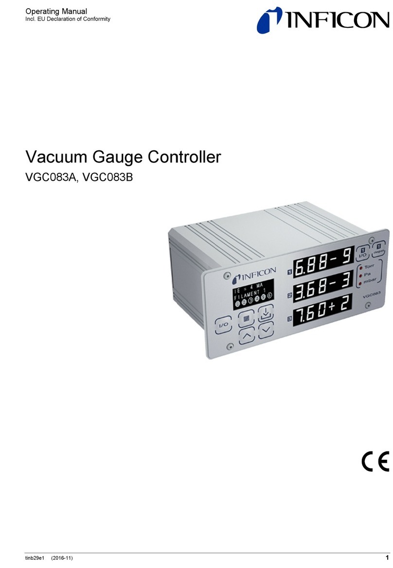
Inficon
Inficon VGC083B User manual
Inficon
Inficon XTC/3 User manual

Inficon
Inficon TPG300 User manual
Inficon
Inficon VGC083C User manual
Inficon
Inficon TPG300 User manual
Inficon
Inficon MAG050 User manual
Inficon
Inficon CU1000 User manual
Inficon
Inficon VGC083A User manual
Inficon
Inficon VGC031 User manual
Inficon
Inficon Cygnus 2 User manual
Popular Controllers manuals by other brands

ZPA Pečky
ZPA Pečky MODACT MTN 15 Mounting instructions
Regin
Regin RVAN10-24 Instruction

IR Ingersoll Rand
IR Ingersoll Rand ARO user manual
Siemens
Siemens SIMATIC S7-1500R/H manual
Mitsubishi Electric
Mitsubishi Electric MELSERVO-JET MR-JET-G Series user manual
Brooks Instrument
Brooks Instrument 5850EM Installation and operation manual
