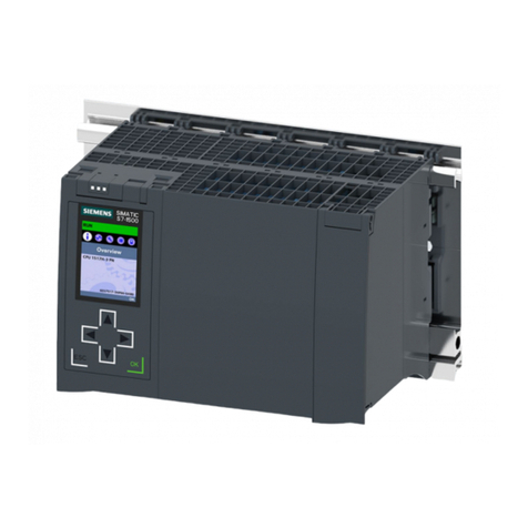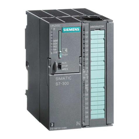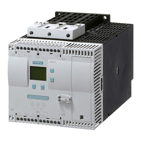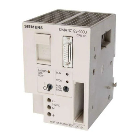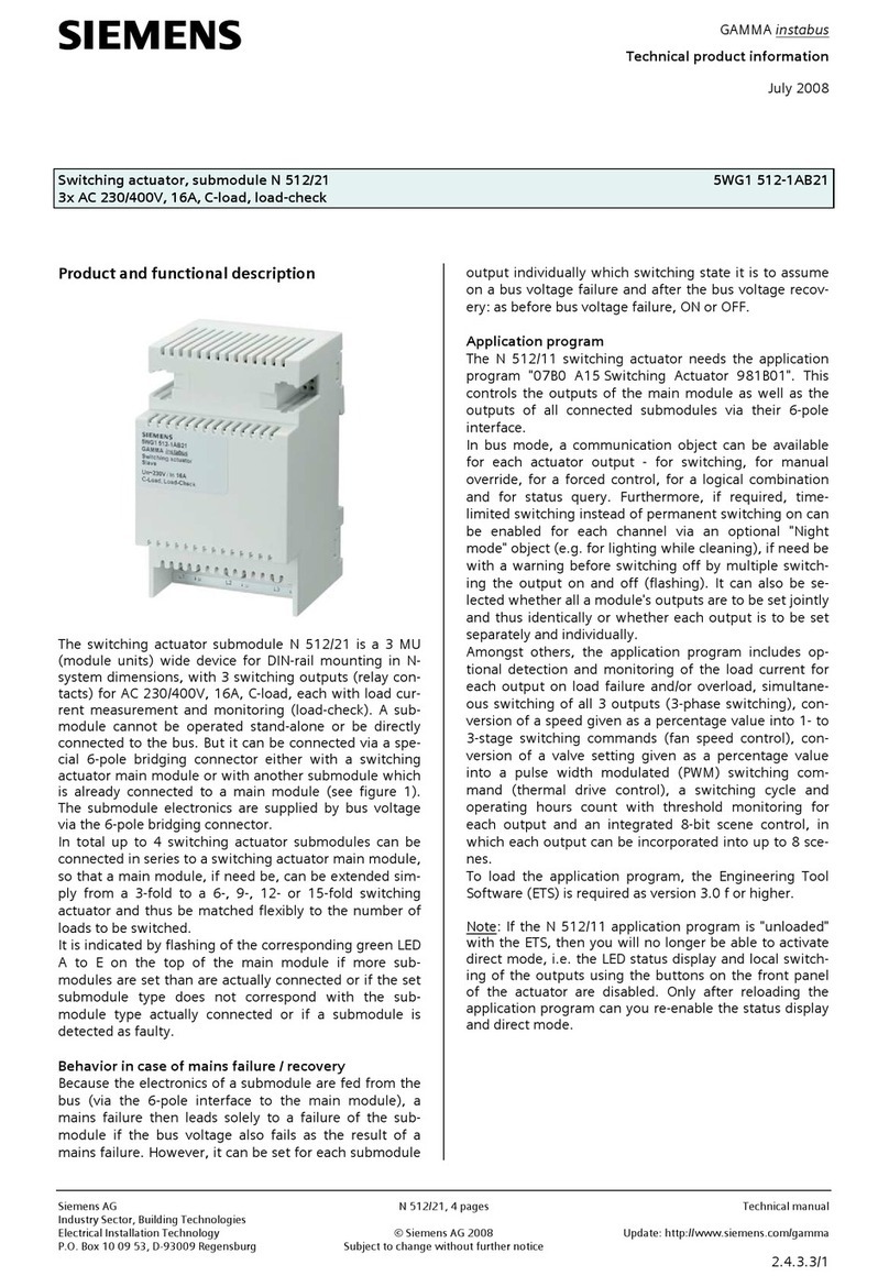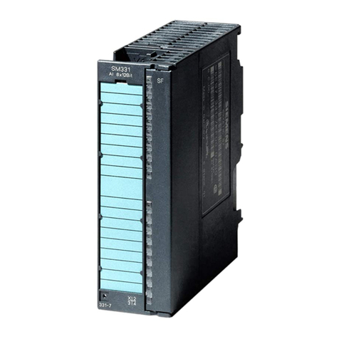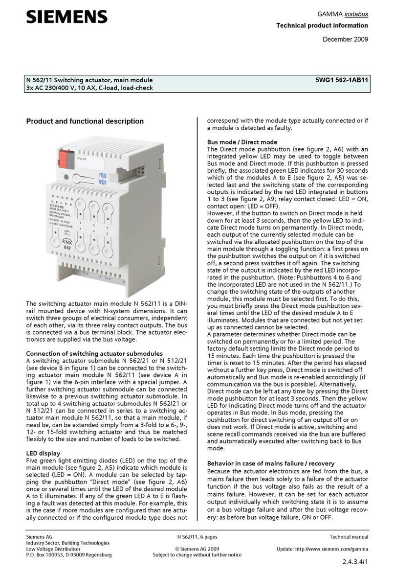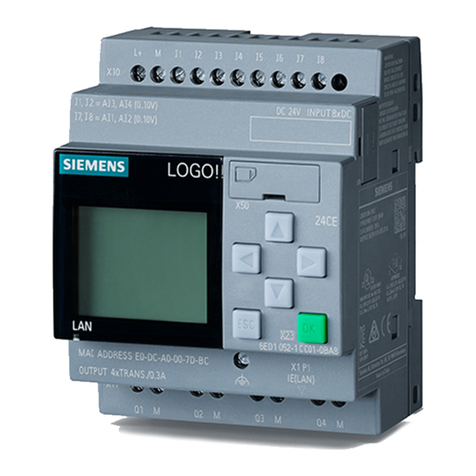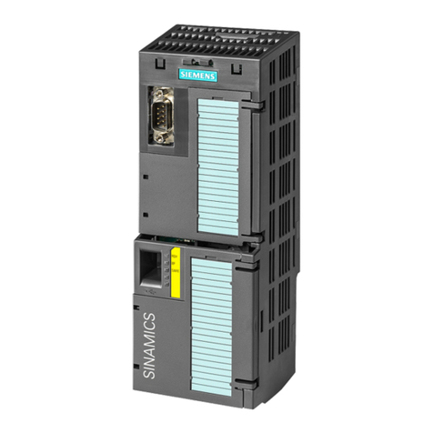
Technology module TM Pulse 2x24V (6ES7138‑6DB00‑0BB1)
6Manual, 09/2015, A5E35061186-AA
Preface ...................................................................................................................................................... 4
1 Documentation guide................................................................................................................................. 8
2 Product overview ..................................................................................................................................... 10
2.1 Properties............................................................................................................................... 10
3 Modes and Functions .............................................................................................................................. 14
3.1 Overview ................................................................................................................................ 14
3.2 Pulse output (single pulse) mode........................................................................................... 17
3.3 Pulse width modulation (PWM) mode.................................................................................... 25
3.4 Pulse train mode .................................................................................................................... 36
3.5 On/Off-delay mode................................................................................................................. 46
3.6 Frequency output mode ......................................................................................................... 57
3.7 DC motor mode...................................................................................................................... 65
3.8 Function: High-speed output.................................................................................................. 74
3.9 Function: Sequence counter.................................................................................................. 75
3.10 Function: Current measurement ............................................................................................ 76
3.11 Function: Current control ....................................................................................................... 78
3.12 Function: Dither PWM output................................................................................................. 82
3.13 Function: Isochronous mode.................................................................................................. 86
3.14 Function: Direct control of DQ digital outputs ........................................................................ 87
4 Connecting .............................................................................................................................................. 91
4.1 Pin assignment, sensor, load, and power wiring ................................................................... 91
5Configuring .............................................................................................................................................. 98
5.1 Configuration software ........................................................................................................... 98
5.2 Configuration overview .......................................................................................................... 99
5.3 Required I/O address space ................................................................................................ 100
5.4 TIA portal Device configuration............................................................................................ 101
5.4.1 TIA Portal Device configuration ........................................................................................... 101
5.4.2 General information ............................................................................................................. 102
5.4.3 Potential group..................................................................................................................... 102
5.4.4 Channel configuration: (4 A) single or (2 A) dual channel operation................................... 102
