manuals.online logo
Brands
  1. Home
  2. •
  3. Brands
  4. •
  5. Infortrend
  6. •
  7. Storage
  8. •
  9. Infortrend EonStor DS 1000 Series User manual

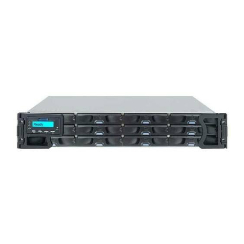
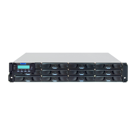
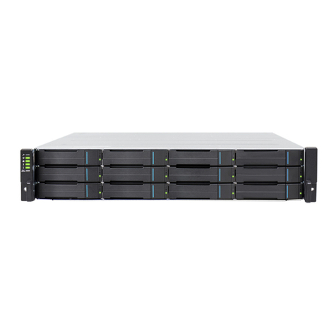
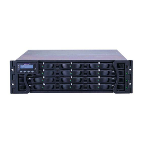
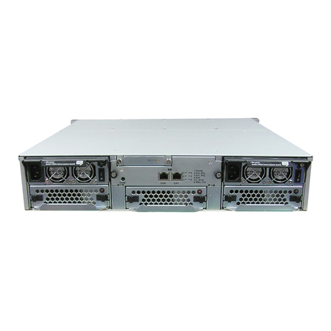
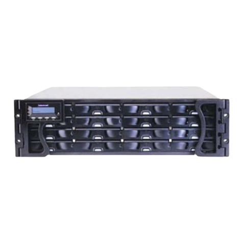
Infortrend EonStor DS 1000 Series User manual

• Only qualified service personnel should install and service this product to avoid injury.
• Observe all ESD procedures during installation to avoid damaging the equipment.
Unpack the equipment and make sure the following tools are available before installation.
1Preparing tools
Warning
1-1. User-provided tools
• Phillips screwdriver (mid-size)
• Flat blade screwdriver (small-size)
• Anti-static wrist wrap
Refer to the Unpacking List for the exact amount of items included in the package.
2Rackmount Installation
1-2. Accessory box content
• Screws: M5, M6, #10-32, #6-32
• Cables: Power cord x 2
© by Infortrend Technology, Inc. All rights reserved.
Z M0 0 0 1 1 0 G A Q0 2 8 1 3
EonStor DS 1000 Series
Quick Installation Guide
b. Attaching the HDD
1. The interface connector should face the open side of
the tray, while the label side should face up.
3-3. Inserting and securing the HDD tray
1. Insert with the tray bezel open. 2. Close the bezel, use a small-size flathead screwdriver,
turn the bezel lock to the lock position.
There are two optional rackmounting kits available. Depending on the one you purchased, refer to the
following installation instructions.
2. Secure the drive by fastening four (4) of the
supplied screws.
a. 3.5" SAS HDD
3.5" SATA HDD in single-controller systems
b. 3.5" SATA HDD in dual-controller systems
a. 2.5" SAS HDD (without MUX)
b. 2.5" SATA HDD (with MUX)
c. MUX board screw locations
3-2.Standard form factor
HDD (3.5")
Press the release button to open the bezel
and gently pull the HDD tray out of the enclosure.
2-1. Rack Ear Mount Kit
Item Description Quantity
01
02
03
04
05
06
07
08
Mounting bracket assembly, left-side
Mounting bracket assembly, right-side
Hexagon washer screws #6-32mm
Truss head screws M5 x 9.0mm
M5 cage nuts
M5 x 25mm
M6 x 25mm
#10-32 x 25.4mm
1
1
8
4
4
4
4
4
a. Contents
b. Installation
1. Determine the exact position where the enclosure will be installed on the rack post (front and rear).
2. Insert the cage nuts into the front rack post.
Positions for chassis / M5 cage nut:
3U, M5 cage nut position
Front rack posts
Unit boundary
Unit boundary
05
2U, M5 cage nut position
05
Rear rack posts
M5 x 9.0mm
04
3. Install the fixed rails to the rear posts and secure them using truss head screws.
Warning
Due to the weight of the enclosure and installation procedure requirements, DO NOT
install HDDs before rackmounting and at least one other personnel should assist with
the installation.
3 #6-32
6 M5 x 25mm
6 M5 x 25mm
NOTE
2-2. Slide Rail Kit
a. Contents
If the rack did not require M5 cage nuts and has its own screw threads, then use the M6
or #10-32 screws for the front posts.
5
2
3
46
78
1
9
Item Description Quantity
01
02
03
04
05
06
07
08
09
Mounting bracket assembly, left-side
Mounting bracket assembly, right-side
Inner glides
Flathead screws #6-32 L4
Truss head screws M5 x 9.0mm
M5 cage nuts
M5 x 25mm
M6 x 25mm
#10-32 x 25.4mm
1
1
2
6
8
4
4
4
4
b. Installation
1. Determine the exact position for enclosure installation (front and rear rack posts).
2. Refer to the illustration below to insert cage nuts into the front rack post and truss head screws to secure
the slide rail.
Positions for chassis / M5 cage nut: Please refer to Rack Ear Mount Kit’s section.
3. Adjust the length by loosening the four screws on the slide rail. Secure the slide rails to front and rear
posts using truss head screws and tighten the four screws on the slide to fix the length.
4. Attach the inner glides to BOTH sides of the enclosure using flathead screws #6-32.
M5 x 9.0mm
05
M5 x 9.0mm
05 Inner glide rail
5. With the assistance of another person, lift and insert the enclosure onto the slide rail. Make sure the inner glides on both
sides of the enclosure meets the inner glide rail. Secure the enclosure using M5 or M6 screws from the front.
4. With one person holding the enclosure at the installation height, the other person can secure the enclosure
in place by placing four M5 x 25mm screws at the front and eight #6-32 screws on both sides (four on each
side).
M5 x 9.0mm
04
#6-32
08
5
1
2
3 4
6 7 8
3Installing HDD
3-1. Small form factor HDD (2.5")
a. Removing the HDD tray
1. Press on the release button to open the bezel
and gently pull the hard drive tray out of the
enclosure.
b. Attaching the HDD
1. Place the hard drive into the drive tray. The
interface connector should face the open
side of the tray, while the label side should
face up. with the label of the hard drive
facing up.
2. Secure the HDD onto the tray according
to the following screw positions.
Lock
Unlock
Release button
Tray
bezel
a.Removing the HDD tray
3U / 36-bay model
a
b
2.5 inch SAS HDD
(without MUX board)
2.5 inch SATA HDD
(with MUX board)
3U / 36-bay model
2.1 3U / 36-bay model only:
Once fully inserted, close the bezel till it's snapped.
aa
bb
a
bb
ac
NOTE
The 2.5 inch drive trays of the 3U / 36 bay model are not compatible with 2.5 inch drive trays
of other Small Form Factor (SFF) models. Make sure the installed drive tray model first
before replacing it. Replace drive trays only with corresponding model. Inserting the wrong
drive tray model can lead to serious hardware damage.
NOTE
6
PSU LED:
PSU LED: On ( )• green
Powering up
6-1.
Connect the power cords to the power socket (in ) on both PSUs.
Connecting the power cord
blue
7-2.
You may control the RAID system using the firmware menu (through the RS-232C
interface) or the SANWatch GUI software (through the Ethernet or host PC interface).
For more tools and their details, refer to the manuals in the CD-ROM.
Firmware menu:
1. Connect your computer to the RAID system through an RS-232C cable.
2. Open a terminal emulation software such as VT-100 on your PC.
3. Configure the serial port as shown in the previous section and connect the RAID system.
The main firmware menu will appear.
4. Use the cursor keys to select the menu.
SANWatch:
1. Connect the RAID system to a remote computer through the Ethernet port or to a
host PC through the host links.
2. Install the SANWatch software suite, included in the CD-ROM, into your computer.
3.
4. On SANWatch, select the RAID system from the Connection View.
5. Go to the Tasks section and select the License Information and generate a
License Application File.
6. Visit http://www.infortrend.com/DSLS to register software license. The license number
is attached in the software license envelop.
7. Activate software features using the license information and continue operating
SANWatch.
Accessing management tools
Install EonPath (multi-pathing driver) ONLY to Windows 2003 based servers. Other
OS use their build-in native multi-pathing driver.
The functions and settings available in each tool are different from each other.
For more details, consult the respective manuals.
Note:
• Host PC (in-band connection): users will access the RAID system from the host servers
through the host links.
• Ethernet Management port (Out-of-band connection): You can access the RAID system
from a remotely connected computer through the Ethernet cable. You need to obtain the IP
address, static IP address or DHCP, from your network administrator. If neither is available,
use the default address < 10.10.1.1>.
• Serial port: You can access the RAID
system from a directly connected
computer through the RS-232C port.
(The serial cable is provided as an
accessory for dual-controller models.
For single-controller models, the serial
cable is user-supplied.)
Serial port setting:
Baud rate: 38400
Data bit: 8 bit
Parity: none
Stop bit: 1
Flow control: hardware
6-2. Powering up the equipment
1. Power up the networking devices.
2. Power up the JBODs (if applied) by pressing the power switches on the rear panel.
3. Power up the RAID system by pressing both power switches (shown above in ) on the
rear panel.
4. Power up the application servers.
green
Front panel LEDs:
0
2
4
6
8
10
12
14
6-3.
Observe the front of the enclosure. If the LED indicators show different status than
described below, or if you hear an audible alarm, contact customer support.
Verifying the status LEDs (front of enclosure)
Drive tray:
7-1. Overview of management interfaces
Connecting to Management Interfaces
7
Managing and monitoring the RAID system is available through three types of interfaces.
Refer to the sample figures below on controller host ports and management interfaces:
Host board host ports
JBOD SAS
expansion
Serial port
Ethernet
management port
Onboard iSCSI host ports
6-4.
Observe the rear of the enclosure. If the LED indicators show different status than
described below, or if you hear an audible alarm, contact customer support.
Verifying the status LEDs (rear of enclosure)
Controller LEDs:
1. Ctrl Status LED: On ( )
2. C_Dirty LED: Off
3. Temp LED: Off
green
1 2 3
4 5 6
4. CBM Status LED: On ( ) or Off
5. Hst Bsy LED: On ( )
6. Drv Bsy LED: On ( )
green
green
green
PSU LED
PSU LED
The below diagrams show the recommended connections among the RAID system,
switches, and the hosts.
For more information, refer to the hardware manual available in the product CD-ROM.
Making host connections
Host link cables are not included in the product package.
5
4JBOD Connections
4-1. Setting the JBOD IDs
Use a small flat blade screwdriver to set the
JBOD enclosure ID(s). A different ID number
must be allocated for each JBOD.
RAID systems are assigned
with ID “0" by default.
Dual controller models
st
• RAID system top SAS exp. – 1 JBOD top SAS-IN
st nd
• 1 JBOD top SAS-OUT – 2 JBOD top SAS-IN
st
• 1 JBOD bottom SAS-IN port – 2nd JBOD bottom SAS-OUT
• RAID system bottom SAS exp. – last JBOD bottom SAS-IN
Single controller models
• RAID system SAS exp. – 1st JBOD SAS-IN
• 1st JBOD SAS-OUT– 2nd JBOD SAS-IN
To ensure redundancy, dual controller SAS expansion must be connected to the opposite
ends of daisy-chained JBODs (eg. first JBOD and last JBOD).
System LED: Green
Service LED: Off
Power LED: Green
Cooling fan LED: Green
Thermal LED: Green
/
3U / 36-bay model
3.5 inch
2.5 inch 3U / 36-bay model only
2.5 inch
1. Drive Activity LED:
On = Drive plugged-in
( )
Flashing = R/W activity ( )
Blue
Blue
2. Power Status LED:
On ( )
Failure ( )
Green
Red
0
2
4
6
8
10
12
14
0
2
4
6
8
10
12
14
Service
1st JBOD
Last JBOD
2nd JBOD
.
.
.
IN OUT
1st JBOD
Last JBOD
2nd JBOD
.
.
.
IN OUT
0
2
4
6
8
10
12
14
4-2. Making the connections
Connect the cables between the RAID system and the JBOD(s).
3U / 36-bay model
Mute /
Service
Service
Mute /
Service
0
2
4
6
8
10
12
14
2
1
2
1
2
1
Single Controller RAID System Dual Controller RAID System Switch Switch
RAID System
Host
Host
HBA 1 HBA 0
HBA 1
HBA 0

Other Infortrend Storage manuals

Infortrend EonStor GSa 3000 User manual

Infortrend

Infortrend EonStor GSa 3000 User manual

Infortrend EonNAS 1000 Series User manual

Infortrend

Infortrend EonNAS 1000 Series User manual

Infortrend EonNAS Pro 500 User manual

Infortrend

Infortrend EonNAS Pro 500 User manual

Infortrend EonStor GS Series User manual

Infortrend

Infortrend EonStor GS Series User manual

Infortrend EonStor DS 3000 Series User manual

Infortrend

Infortrend EonStor DS 3000 Series User manual

Infortrend EonStor S12E-R1132-4 User manual

Infortrend

Infortrend EonStor S12E-R1132-4 User manual

Infortrend EonStor CS Series User manual

Infortrend

Infortrend EonStor CS Series User manual

Infortrend EonNAS Pro 500 User manual

Infortrend

Infortrend EonNAS Pro 500 User manual

Infortrend EonStor CS Series User manual

Infortrend

Infortrend EonStor CS Series User manual

Infortrend EonStor DS 4000 Series User manual

Infortrend

Infortrend EonStor DS 4000 Series User manual

Infortrend EonStor A12E-G2121 User manual

Infortrend

Infortrend EonStor A12E-G2121 User manual

Infortrend EonStor GS 3000 Series User manual

Infortrend

Infortrend EonStor GS 3000 Series User manual

Infortrend EonStor GS 1000 Gen2 User manual

Infortrend

Infortrend EonStor GS 1000 Gen2 User manual

Infortrend EonStor A16F User manual

Infortrend

Infortrend EonStor A16F User manual

Infortrend S12 Series User manual

Infortrend

Infortrend S12 Series User manual

Infortrend EonStor S12S-G1033 User manual

Infortrend

Infortrend EonStor S12S-G1033 User manual

Infortrend EonStor DS 1024B User manual

Infortrend

Infortrend EonStor DS 1024B User manual

Infortrend EonStor F16F-R4031-6/4 User manual

Infortrend

Infortrend EonStor F16F-R4031-6/4 User manual

Infortrend EonServ 5000 Gen2 Series User manual

Infortrend

Infortrend EonServ 5000 Gen2 Series User manual

Infortrend EonStor GS Series Operating manual

Infortrend

Infortrend EonStor GS Series Operating manual

Infortrend EonNAS Pro Series User manual

Infortrend

Infortrend EonNAS Pro Series User manual

Infortrend EonStor S12F-R1432 User manual

Infortrend

Infortrend EonStor S12F-R1432 User manual

Infortrend EonStor DS 3000 Series User manual

Infortrend

Infortrend EonStor DS 3000 Series User manual

Infortrend EonStor GSe Pro 108 User manual

Infortrend

Infortrend EonStor GSe Pro 108 User manual

Popular Storage manuals by other brands

SMA Home Storage HS-BM-3.28-10 manual

SMA

SMA Home Storage HS-BM-3.28-10 manual

Seagate ST-506 product manual

Seagate

Seagate ST-506 product manual

Transcend USB JetFlash user manual

Transcend

Transcend USB JetFlash user manual

Seagate FreeAgent Theater quick start guide

Seagate

Seagate FreeAgent Theater quick start guide

Linn KIVOR LINNK manual

Linn

Linn KIVOR LINNK manual

Copernicus VRT101 Assembly guide

Copernicus

Copernicus VRT101 Assembly guide

Seagate SKYHAWK SURVEILLANCE ST8000VX0022 product manual

Seagate

Seagate SKYHAWK SURVEILLANCE ST8000VX0022 product manual

Transcend JetFlash TS2GJFT5T Specification sheet

Transcend

Transcend JetFlash TS2GJFT5T Specification sheet

Sun Microsystems Sun StorageTek 5800 Reference manual

Sun Microsystems

Sun Microsystems Sun StorageTek 5800 Reference manual

IBM BladeCenter S 7779 user manual

IBM

IBM BladeCenter S 7779 user manual

Philips Active Crystals FM02SW30 Specifications

Philips

Philips Active Crystals FM02SW30 Specifications

Sony CSM-100BS operating instructions

Sony

Sony CSM-100BS operating instructions

Fujitsu MHE2043AT product manual

Fujitsu

Fujitsu MHE2043AT product manual

Supero SUPERSTORAGE 5048R-E1CR36L user manual

Supero

Supero SUPERSTORAGE 5048R-E1CR36L user manual

Transcend JetFlash 220 Brochure & specs

Transcend

Transcend JetFlash 220 Brochure & specs

ZyXEL Communications NAS Series user guide

ZyXEL Communications

ZyXEL Communications NAS Series user guide

HP Model 744 - VME Workstation Declaration of conformity

HP

HP Model 744 - VME Workstation Declaration of conformity

CalDigit AVPro2 user guide

CalDigit

CalDigit AVPro2 user guide

manuals.online logo
manuals.online logoBrands
  • About & Mission
  • Contact us
  • Privacy Policy
  • Terms and Conditions

Copyright 2025 Manuals.Online. All Rights Reserved.