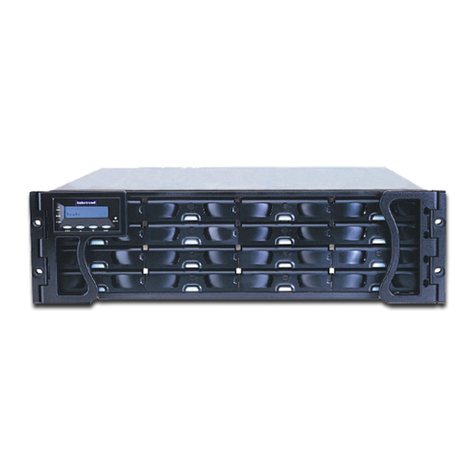
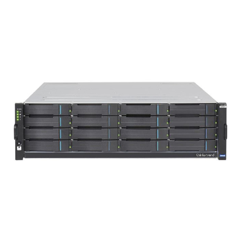
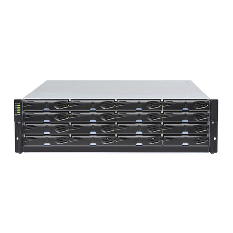
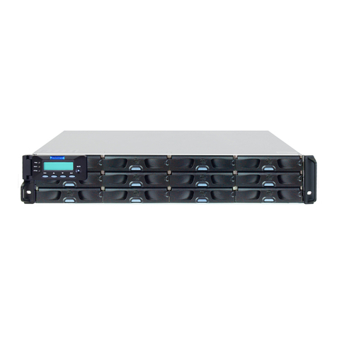
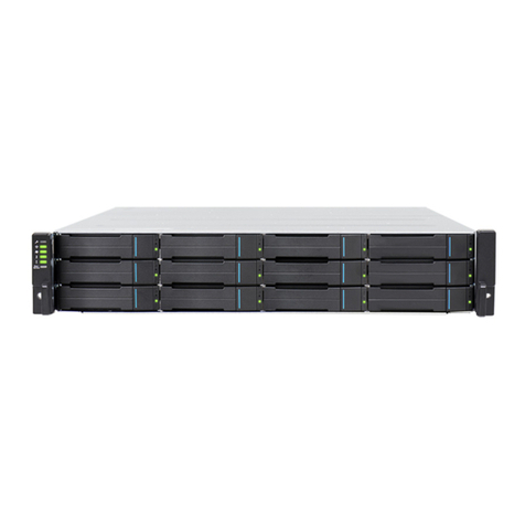
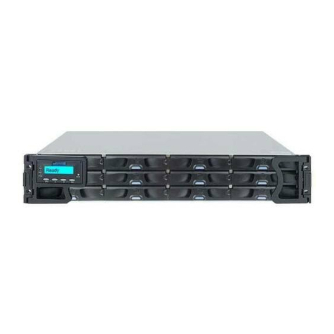
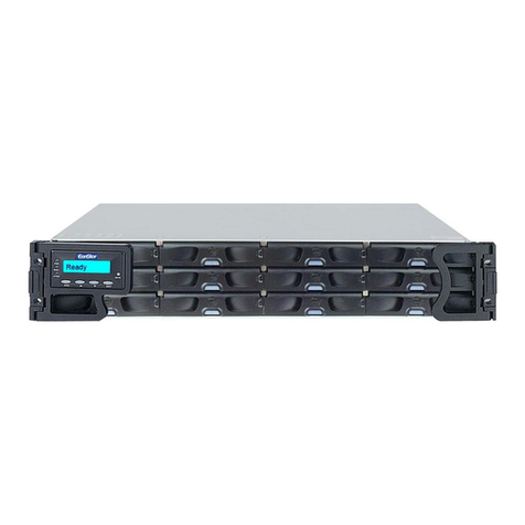
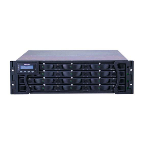
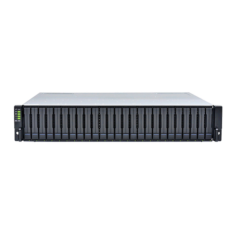
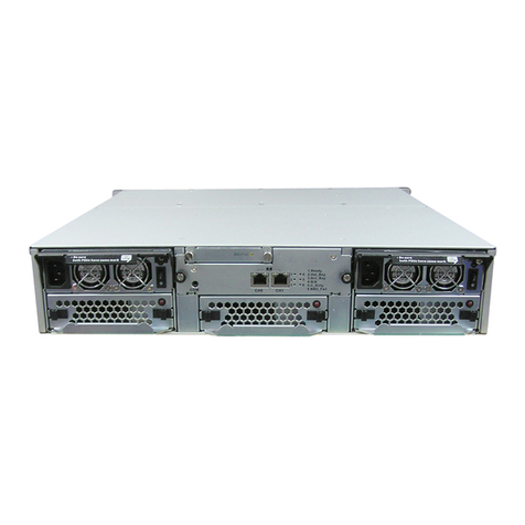
EonStor F16F-R/S4031-6/4 Installation and Hardware Reference Manual
vii
1.2.4 BBU ...................................................................................................................... 1-18
1.2.5 PSUs ..................................................................................................................... 1-19
1.2.6 Cooling Modules................................................................................................... 1-20
1.2.7 Host I/O Modules.................................................................................................. 1-21
1.2.8 Drive/Host Expansion I/O Modules...................................................................... 1-22
1.3 SYSTEM MONITORING ................................................................................. 1-23
1.3.1 I2C bus.................................................................................................................. 1-23
1.3.2 LED Indicators ..................................................................................................... 1-24
1.3.3 Firmware and RAIDWatch GUI ........................................................................... 1-24
1.3.4 Audible Alarms ..................................................................................................... 1-24
1.4 HOT-SWAPPABLE COMPONENTS ................................................................. 1-25
1.4.1 Hot-swap Capabilities .......................................................................................... 1-25
1.4.2 Components .......................................................................................................... 1-25
1.4.3 Normalized Airflow............................................................................................... 1-25
CHAPTER 2 HARDWARE INSTALLATION
2.1 INTRODUCTION ............................................................................................. 2-1
2.2 INSTALLATION PREREQUISITES...................................................................... 2-1
2.3 SAFETY PRECAUTIONS:................................................................................. 2-2
2.3.1 Precautions and Instructions.................................................................................. 2-2
2.3.2 Static-free Installation ............................................................................................ 2-3
2.4 GENERAL INSTALLATION PROCEDURE ........................................................... 2-3
2.4.1 Installation Procedure Flowchart........................................................................... 2-4
2.5 UNPACKING THE SUBSYSTEM........................................................................ 2-5
2.6 INSTALLATION OVERVIEW ............................................................................. 2-6
2.6.1 Preinstalled Components........................................................................................ 2-6
2.6.2 Components to be Installed..................................................................................... 2-6
2.7 RACKMOUNTING ........................................................................................... 2-6
2.8 ENCLOSURE BAY NUMBERING AND DRIVE ID ALLOCATION ............................ 2-7
2.9 HARD DRIVE INSTALLATION........................................................................... 2-7
2.9.1 Hard Drive Installation Prerequisites..................................................................... 2-7
2.9.2 Drive Installation.................................................................................................... 2-8
2.10 DRIVE TRAY INSTALLATION ........................................................................... 2-9
CHAPTER 3 SUBSYSTEM CONNECTION
3.1 HOST CONNECTION PREREQUISITES.............................................................. 3-1
3.1.1 The Fiber Optical Cables..................................................................................................... 3-1
3.2 TOPOLOGY AND CONFIGURATION CONSIDERATIONS....................................... 3-2
3.2.1 Basic Configuration Rules.................................................................................................... 3-2
3.3 CONFIGURATION OPTIONS ............................................................................ 3-3
3.3.1 Port Assignments.................................................................................................................. 3-3
3.3.2 DIP Switch ........................................................................................................................... 3-4
3.3.3 Changing the Channel Mode................................................................................................ 3-6
3.3.3.1 Via Hyper Terminal........................................................................................................... 3-6
3.3.3.2 Via RAIDWatch Manager.................................................................................................. 3-7
3.4 SAMPLE TOPOLOGIES................................................................................... 3-9
3.4.1 Host-side Connection......................................................................................................... 3-10
3.4.2 Expansion Links ................................................................................................................. 3-12
3.5 POWER ON................................................................................................. 3-18
3.5.1 Check List........................................................................................................................... 3-18
3.5.2 Power On Procedure.......................................................................................................... 3-18
3.5.3 Power On Status Check...................................................................................................... 3-20
3.5.4 LCD Screen........................................................................................................................ 3-21
3.6 POWER OFF PROCEDURE ........................................................................... 3-22
CHAPTER 4 SYSTEM MONITORING
4.1 SYSTEM MONITORING OVERVIEW .................................................................. 4-1
4.2 STATUS-INDICATING LEDS............................................................................ 4-3
4.2.1 LED Overview ........................................................................................................ 4-3
4.2.2 LCD Keypad Panel................................................................................................. 4-3
4.2.3 Drive Tray LEDs..................................................................................................... 4-4
4.2.4 Controller Module LEDs ........................................................................................ 4-5
4.2.4.1 Controller Status LEDs............................................................................................4-6
4.2.4.2 Fibre Port LEDs.......................................................................................................4-6
4.2.4.3 Restore Default LED ...............................................................................................4-7
4.2.4.4 Ethernet Port LEDs..................................................................................................4-7
