EonServ
EonServ 5000 Gen2 Series
Storage System
Quick Installation Guide
WARNING!
• Only qualied service personnel should install and service this product to avoid injury.
• Observe all ESD procedures during installation to avoid damaging the equipment.
1 Preparing the tools
Unpack the equipment and ensure that the following tools are available before installation.
1.1 User-provided tools
• Phillips screwdriver (medium size)
• Flat blade screwdriver (small size)
• Anti-static wrist wrap
• Host link cables
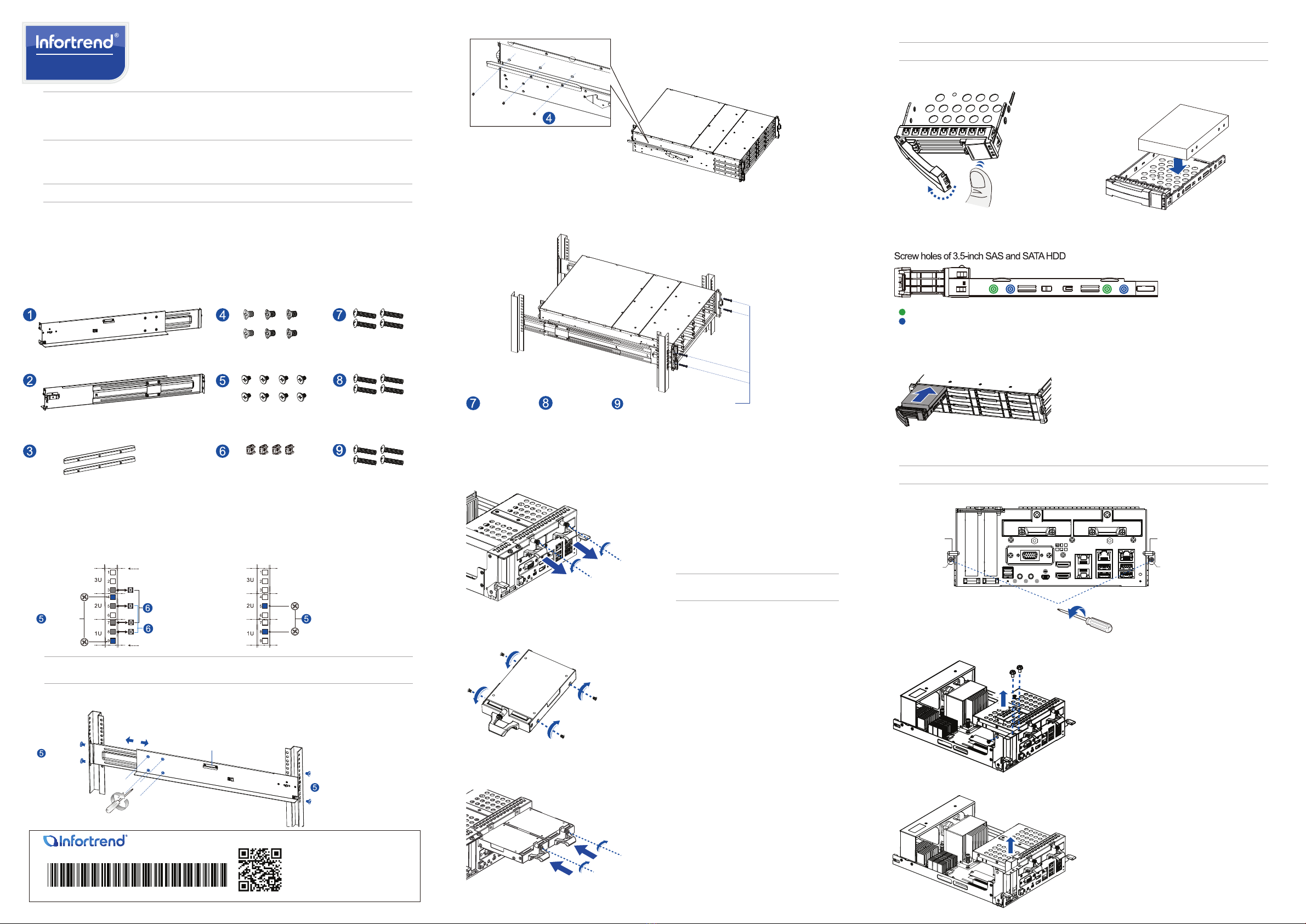
2 Installing the slide rail kit
2.1 Checking the contents of the slide rail kit
NOTE: Refer to the Unpacking List for the exact number of items bundled in the package.
2.2 Assembling the slide rail kit
1. Determine the position where the enclosure will be installed to the front and rear rack posts, then insert the cage
nuts into the designated holes of the front rack posts.
1 x Mounting bracket assembly, left side
1 x Mounting bracket assembly, right side
2 x Inner glides
6 x No. 6-32 L4
Flathead screws
8 x M5 9.0mm
Truss head screws
4 x M5 cage nuts
4 x M5 25mm screws
4 x M6 25mm screws
4 x No. 10-32
25.4mm screws
M5 9.0mm
Rear rack postFront rack post
Unit boundary
Unit boundary
3U, M5 cage nuts
M5 9.0mm
2U, M5 cage nuts
Inner glide rail
M5 9.0mm
M5 9.0mm
2. Loosen the four screws on the slide rail to adjust the length. After the length adjustment, secure the slide rails to
the front and rear posts with the truss head screws. Tighten the four screws on the slide rail to x the length.
3. Attach the inner glides to both sides of the enclosure using the athead screws no. 6-32.
4. With the assistance of another person, lift and insert the enclosure onto the slide rail. Ensure that the inner
glides on both sides of the enclosure meet the inner glide rail. Flip open the side covers by the handles. Secure
the enclosure using the M5, M6, or no. 10-32 screws from the front.
No. 6-32
M5 25mm or M6 25mm or No. 10-32 25.4mm screws
3 Installing the system drive
There are two 2.5-inch system drive slots at the rear panel of the system. If you purchased the system with the hard
drive(s), they should have been assembled together. If not, you must install them following these steps:
1. Loosen the screw.Gently pull out the drive tray from the enclosure.
IMPORTANT! Use the left drive slot when you install
only one system hard drive.
4 Installing the hard drives
IMPORTANT! Ensure to install the chassis to the rack before installing the hard drives into the chassis.
2. Orient the hard drive to the tray with the interface
connectors facing the open side of the tray and the
label is facing up.
1. Press the release button to open the spring
handle.
3. Secure the drive to the correct holes of the tray using the four bundled screws.
HDD with MUX board (not applicable for single controller systems)
HDD without MUX board
4. Insert the assembled hard drive and tray to the enclosure with the spring handle open, then close the spring
handle when the drive is fully inserted to the bay.
5 Installing a PCIe card (optional)
IMPORTANT! Conrm with your support personnel about PCIe card qualication before purchase/installation.
2. Loosen the screws and remove the cover.
1. Remove the mounting screws. Push down the ejection levers to dislodge the controller from the enclosure.
Ejection lever
Ejection lever
Mounting screw Mounting screw
2. Orient the hard drive to the tray with the interface connectors facing the open side of the tray and the label is
facing up. Secure the drive to the correct holes of the tray using the four bundled screws.
3. Insert the assembled drive and tray into the enclosure. Tighten the screws.
© by Infortrend Technology, Inc. All rights reserved.
Scan QR code for more technical
document information.
ZM000110GAQ09310
NOTE: If the rack does not require M5 cage nuts and has its own screw threads, use the M6 or No. 10-32 screws on the
front posts.
3. Remove the dummy bracket.


