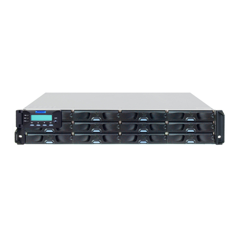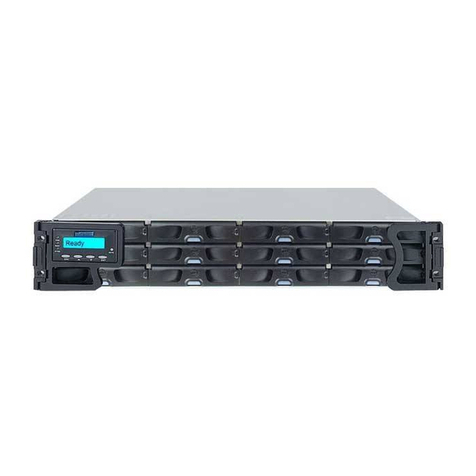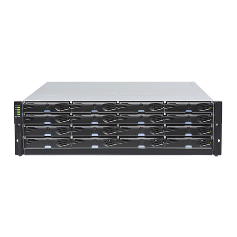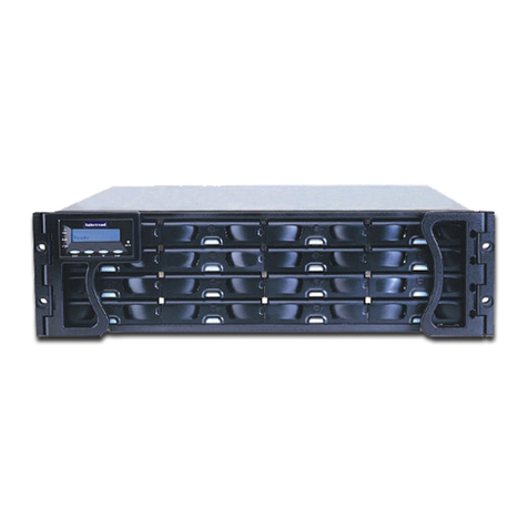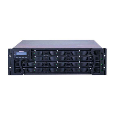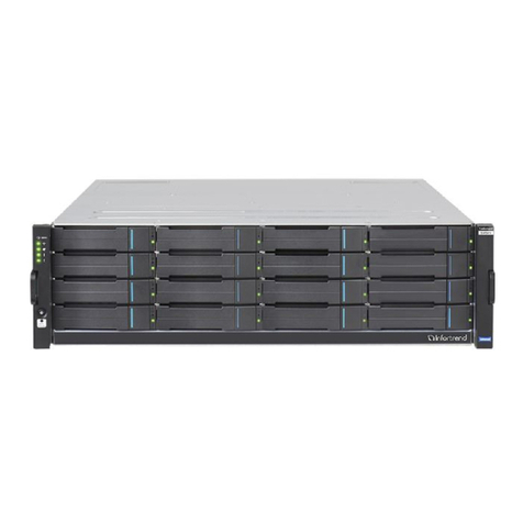
EonStor S12S-G1033/P Installation and Hardware Reference Manual
ix
3.1.1 Host Link Cables....................................................................................... 3-1
3.1.2 Other Concerns......................................................................................... 3-2
3.2 SAMPLE TOPOLOGY...................................................................................... 3-4
3.3 EXPANSION LINKS ........................................................................................ 3-5
CHAPTER 4
4.1 POWER ON................................................................................................... 4-1
4.1.1 Check List................................................................................................... 4-1
4.1.2 Power On Procedure .................................................................................. 4-1
4.1.3 Power On Status Check ............................................................................. 4-2
4.1.4 LCD Screen ................................................................................................ 4-3
4.2 POWER OFF PROCEDURE ............................................................................. 4-4
4.3 SYSTEM MONITORING OVERVIEW .................................................................. 4-5
4.4 STATUS-INDICATING LEDS............................................................................ 4-6
4.4.1 LED Overview............................................................................................. 4-6
4.4.2 LCD Keypad Panel ..................................................................................... 4-6
4.4.3 Drive Tray LEDs ......................................................................................... 4-7
4.4.4 Controller Module LEDs.............................................................................. 4-8
4.4.4.1 System Status LEDs....................................................................................4-8
4.4.4.2 SAS Port LEDs ............................................................................................4-9
4.4.4.3 Restore Default LED....................................................................................4-9
4.4.4.4 LAN Port LEDs ..........................................................................................4-10
4.4.5 BBU LED .................................................................................................. 4-10
4.4.6 PSU LEDs ................................................................................................ 4-11
4.4.7 Cooling Module LEDs ............................................................................... 4-11
4.5 AUDIBLE ALARM......................................................................................... 4-12
4.5.1 Overview ................................................................................................. 4-12
4.5.2 Failed Devices .......................................................................................... 4-13
CHAPTER 5
5.1 OVERVIEW.................................................................................................... 5-1
5.1.1 About Subsystem Maintenance .................................................................. 5-1
5.1.2 General Notes on Component Replacement .............................................. 5-1
5.2 REPLACING A CONTROLLER MODULE ............................................................ 5-2
5.2.1 Considerations............................................................................................ 5-2
5.2.2 Controller Module Replacement Procedure................................................ 5-3
5.3 REPLACING A DIMM MODULE ....................................................................... 5-4
5.3.1 DIMM Module Considerations .................................................................... 5-4
5.3.2 DIMM Module Upgrade/Replacement Procedure ....................................... 5-5
5.4 REPLACING A FAULTY BBU .......................................................................... 5-6
5.4.1 Notes on BBU Maintenance ....................................................................... 5-6
5.4.2 BBU Replacement Procedure..................................................................... 5-8
5.5 REPLACING A FAULTY PSU .......................................................................... 5-9
5.5.1 PSU Overview ............................................................................................ 5-9
5.5.2 PSU Replacement Procedure................................................................... 5-10
5.6 REPLACING A COOLING MODULE................................................................. 5-12
5.6.1 Notes on Cooling Module Maintenance .................................................... 5-12
5.6.2 Cooling Module Replacement Procedure ................................................. 5-13
5.7 REPLACING A FAILED HARD DRIVE.............................................................. 5-13
5.7.1 Hard Drive Maintenance Overview ........................................................... 5-13
5.7.2 Hard Drive Replacement Procedure ......................................................... 5-14
APPENDIX A
A.1 TECHNICAL SPECIFICATIONS .........................................................................A-1
A.2 FUNCTIONAL SPECIFICATIONS .......................................................................A-2
A.3 POWER SUPPLY SPECIFICATIONS ..................................................................A-3
A.4 COOLING MODULE SPECIFICATIONS ..............................................................A-4
A.5 RAID MANAGEMENT.....................................................................................A-4
A.6 FAULT TOLERANCE MANAGEMENT ................................................................A-4
APPENDIX B
B.1 SAS CONNECTOR PINOUTS ..........................................................................B-1
B.2 COM1 SERIAL PORT CABLE .........................................................................B-2
B.3 COM2 SERIAL PORT CABLE TO UPS............................................................B-2
B.4 IFT-9011 NULL MODEM................................................................................B-4
B.5 ETHERNET PORT PINOUTS ............................................................................B-5
B.6 POWER CONNECTORS ..................................................................................B-5
