Page 2 of 8 SB10X-X-X (en)
OPERATING AND SAFETY PRECAUTIONS
READ, UNDERSTAND AND FOLLOW THIS INFORMATION TO AVOID INJURY AND PROPERTY DAMAGE.
EXPLOSION HAZARD. Do not exceed maximum
uid inlet pressure of 100 PSIG (6.9 bar). Operating at higher
pressure can cause explosion, resulting in property damage or
severe injury.
USE ONLY WITH COMPRESSED AIR. Do not use
bottled gas products to run the Shock Blocker. Unregulated
high pressure bottled gas has the potential for over-pressuriza-
tion. Certain gasses, such as Nitrogen, can cause unpredictable
results. The pressure source MUST BE REGULATED.
TEMPERATURE LIMITATIONS. Do not exceed
maximum temperature limits of; (Polypropylene 175°F),
(Conductive Acetal 180°F), (PVDF 200°F). Excessive oper-
ating temperatures can weaken the body material. Limits are
based on mechanical stress only.
CHEMICAL COMPATIBILITY HAZARD. Do not use
with certain uids. Incompatible uids may attack and weaken
the housing, causing rupture or explosion, which can result in
property damage or severe injury. See manufacturer’s informa-
tion on uid compatibility.
DISASSEMBLY HAZARD. Do not disassemble this
unit when it is under pressure. Relieve all material pressure in
the pumping system before attempting service or disassembly.
Disconnect air lines and carefully bleed any pressure o the sys-
tem. Be certain the system is not maintaining pressure due to
a material restriction in the hose, line, dispensing device or the
spray or extrusion tip. Failure to relieve pressure, both upstream
and downstream, may result in an injury upon disassembly.
MATERIAL ATOMIZATION. The relief / exhaust
valve must be piped away from the work area. In the event of a
bladder rupture, the material can be atomized and forced out
the relief / exhaust valve.
NOT FOR STRUCTURAL SUPPORT. Do not use
this product to support other system components or use
as a step. Improper support can result in fracture of the hous-
ing, causing damage. Plumbing must be supported to prevent
stresses upon it. Install using the mounting hardware supplied.
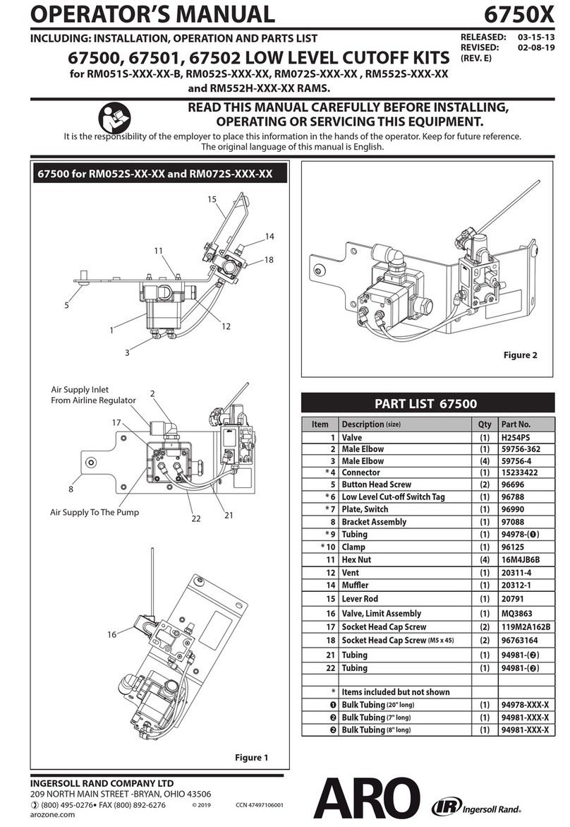
Replacement warning labels (PN 93793) are
available upon request.
= Hazards or unsafe practices which
could result in severe personal injury,
death or substantial property damage.
= Hazards or unsafe practices which
could result in minor personal injury,
product or property damage.
= Important installation, operation or
maintenance information.
GENERAL DESCRIPTION
INSTALLATION INSTRUCTIONS
The ARO® Shock Blocker pulsation dampener is designed to work
with 1:1 ratio pumps having an outlet pressure not exceeding 100
psig (6.9 bar). The Shock Blocker will effectively reduce material
pressure variations, surges and shock to piping and delivery in uid
systems during pump reversal. It can significantly contribute to
pulse reduction in low pressure spray applications.
Accurate selection of wetted material will assure longest service life
and minimize down time. Several material options are available for
the body and bladder materials. Body materials available include:
Polypropylene, Conductive Acetal and PVDF. Use Conductive Acetal
and ground cable when pumping ammable materials.
The Shock Blocker uses a single air pressurized, flexible bladder
working against the fluid line pressure. Several bladder material
options are available to allow custom matching to the uid material
for best compatibility (refer to the model description chart).
The use of an air tamer for a higher level of automatic pressure ad-
justment and accuracy is important. It uses a sensing rod to detect
the position of the bladder and an automatic air valve to adjust
the air line pressure or to exhaust excessive pressure in the bladder
chamber as needed. An air pressure gauge is standard to monitor
the air side internal chamber pressure.
Shock Blocker units can also be added in series to provide addition-
al dampening on the material.
HEED WARNINGS AS SHOWN IN “OPERATING
AND SAFETY PRECAUTIONS’’ ABOVE.
AIR REQUIREMENTS
Clean, dry air should be used to charge the unit. A lter capable of
ltering out particles larger than 50 microns should be used on the
air supply.
INSTALLATION INSTRUCTIONS
Position the Shock Blocker pulsation dampener as close to the
pump discharge as possible.
Use the ground lug and optional 66885-1 grounding cable kit with
the Conductive Acetal models (SB10D-XDS-X) in applications where
ammable uids are used, to help guard against static spark hazard
resulting in possible re or explosion. The terminal on the end of
the ground wire must be removed and the wire stripped back 1/2”
(13 mm) to be accepted by the Shock Blocker ground tting. Mount
the Shock Blocker in one of the recommended positions as illustrat-
ed in gure 2, page 3.
Different materials affect the mounting configuration. For best
performance and typical applications, mount the Shock Blocker up-
right versus horizontally. Heavier particles in some uids may settle
out. Gravity will help discharge heavier particles when mounted
vertically.
In many situations, mounting the unit directly to the pump outlet
would not be advisable due to the added weight of the unit. It
should be independently mounted and plumbed using flexible
tubing and not expected to physically support other components.
The material ow should be in the direction of the Shock Blocker,
for best results, not passing by at right angles (see gure 2, page 3).
Use the mounting base as provided and additional mounting kit
66108 is also available to gain extra vertical height. This may be nec-
essary when using pumps with outlets 1” and larger, because of the
increased size and space requirements of the fittings. The second
mounting kit is inverted to provide an elevated base (see page 7).
When connecting pipe, cut or press the “knock-out” panels from
the pedestal base as needed to accommodate piping. Do not alter
or cut out other parts of the pedestal.
Shock Blockers used in series should be installed as illustrated in
gure 2, page 3.
All models are completely automatic, no further adjustment is
needed after initial set-up. The control device is activated by chang-
es in the material pressure and it will self-adjust the air pressure to
the correct level regardless of the material used. Refer to operating
instructions on page 3.
