manuals.online logo
Brands
  1. Home
  2. •
  3. Brands
  4. •
  5. INOR
  6. •
  7. Transmitter
  8. •
  9. INOR APAQ-HRF User manual

INOR APAQ-HRF User manual

Other INOR Transmitter manuals

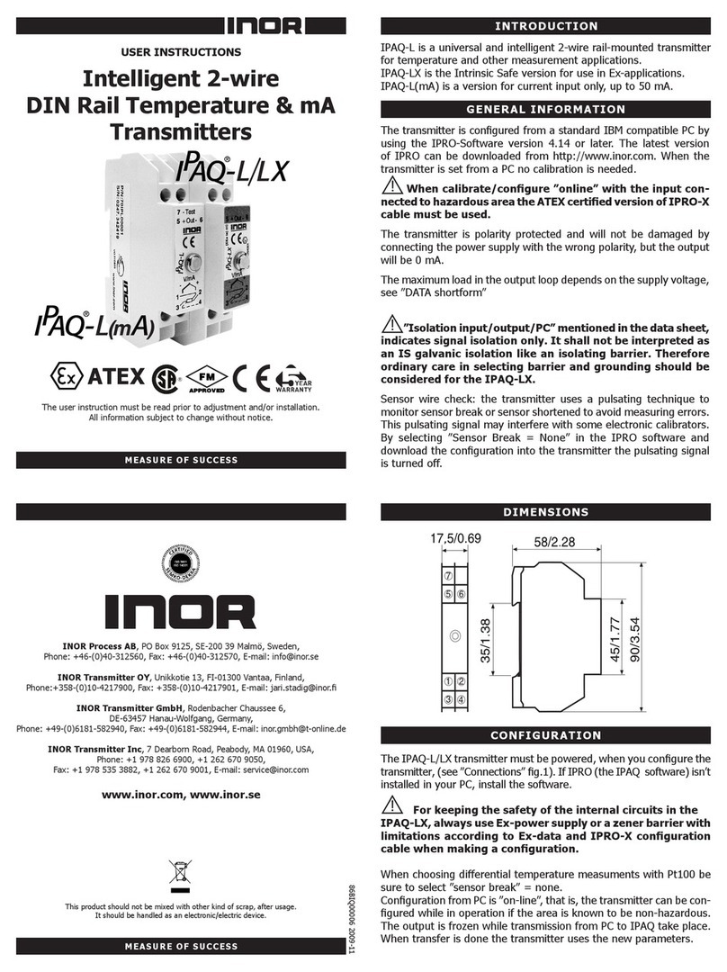
INOR IPAQ-L User manual

INOR

INOR IPAQ-L User manual

INOR ICON-X Wiring diagram

INOR

INOR ICON-X Wiring diagram

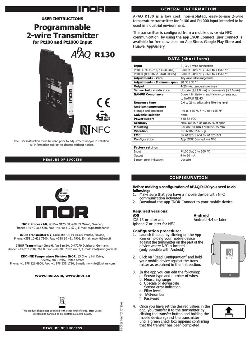
INOR APAQ R130 User manual

INOR

INOR APAQ R130 User manual

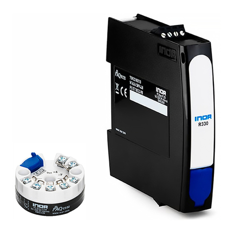
INOR IPAQ C330 Series User manual

INOR

INOR IPAQ C330 Series User manual

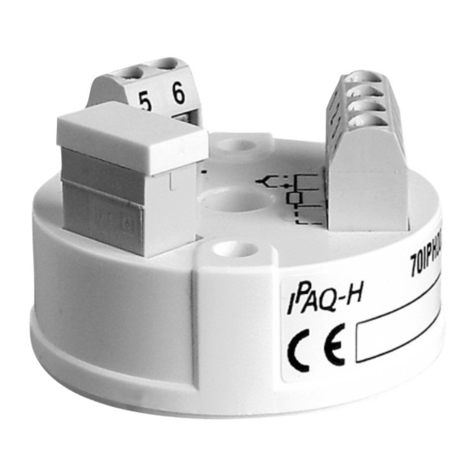
INOR IPAQ-H/HX User manual

INOR

INOR IPAQ-H/HX User manual

INOR IPAQ R202 User manual

INOR

INOR IPAQ R202 User manual

INOR IPAQ C520 User manual

INOR

INOR IPAQ C520 User manual

INOR APAQ C130 TC User manual

INOR

INOR APAQ C130 TC User manual

INOR IPAQ C520 Wiring diagram

INOR

INOR IPAQ C520 Wiring diagram

INOR IPAQ-4L User manual

INOR

INOR IPAQ-4L User manual

INOR IPAQ-LX User manual

INOR

INOR IPAQ-LX User manual

INOR Mini IPAQ-HLP User manual

INOR

INOR Mini IPAQ-HLP User manual

INOR IPAQ CT20 User manual

INOR

INOR IPAQ CT20 User manual

INOR APAQ C130 User manual

INOR

INOR APAQ C130 User manual

Popular Transmitter manuals by other brands

Seneca K120RTD installation manual

Seneca

Seneca K120RTD installation manual

Nautel GV40 installation manual

Nautel

Nautel GV40 installation manual

HumanTechnik cm-light operating instructions

HumanTechnik

HumanTechnik cm-light operating instructions

Linear DXS-64 operating instructions

Linear

Linear DXS-64 operating instructions

FeinTech ABT00102 instruction manual

FeinTech

FeinTech ABT00102 instruction manual

Geo Web Pack quick start guide

Geo

Geo Web Pack quick start guide

Inovonics EchoStream EN1210W installation instructions

Inovonics

Inovonics EchoStream EN1210W installation instructions

IKONNIK KA-6 quick start guide

IKONNIK

IKONNIK KA-6 quick start guide

Rohde & Schwarz SR8000 Series System manual

Rohde & Schwarz

Rohde & Schwarz SR8000 Series System manual

Audio Technica UniPak ATW-T93 Installation and operation

Audio Technica

Audio Technica UniPak ATW-T93 Installation and operation

NIVELCO EasyTREK SCA-300 Series Programming manual

NIVELCO

NIVELCO EasyTREK SCA-300 Series Programming manual

Honeywell 5816WMBR installation instructions

Honeywell

Honeywell 5816WMBR installation instructions

Kamstrup READy MTU Installation and operation guide

Kamstrup

Kamstrup READy MTU Installation and operation guide

Omega ZW Series user guide

Omega

Omega ZW Series user guide

ABB Field 264H Instructions for installation

ABB

ABB Field 264H Instructions for installation

Dejero EnGo 3x manual

Dejero

Dejero EnGo 3x manual

Rosemount 4600 Reference manual

Rosemount

Rosemount 4600 Reference manual

RKI Instruments M2A 65-2643RK-05-04 Operator's manual

RKI Instruments

RKI Instruments M2A 65-2643RK-05-04 Operator's manual

manuals.online logo
manuals.online logoBrands
  • About & Mission
  • Contact us
  • Privacy Policy
  • Terms and Conditions

Copyright 2025 Manuals.Online. All Rights Reserved.

LIMITED WARRANTY
Always use the cover when the transmitter is
not in the configuration phase. The cover
prevents the transmitter from getting dirt on
the soldering pads as well as getting ESD by
accidental touch of the soldering pads.
Connect input, output and power supply acc.
to fig. 2.
A convinient way to install the transmitter is
to use the INOR mounting kits for in-head and
DIN rail mounting, see figure 4 and 5. In order
to minimize measuring errors make sure the
connecting screws are tightened enough.
INOR Process AB, or any other affiliated company within the Inor Group (hereinafter jointly referred
to as ”Inor”), hereby warrants that the Product will be free from defects in materials or workmanship
for a period of five (5) years from the date of delivery (”Limited Warranty”). This Limited Warranty
is limited to repair or replacement at Inor’s option and is effective only for the first end-user of the
Product. Upon receipt of a warranty claim, Inor shall respond within a reasonable time period as to
its decision concerning:
1 Whether Inor acknowledges its responsibility for any asserted defect in
materials or workmanship; and, if so,
2 the appropriate cause of action to be taken (i.e. whether a defective product should be
replaced or repaired by Inor).
This Limited Warranty applies only if the Product:
1 is installed according to the instructions furnished by Inor;
2 is connected to a proper power supply;
3 is not misused or abused; and
4 there is no evidence of tampering, mishandling, neglect, accidental damage,
modification or repair without the approval of Inor or damage done to the Product by
anyone other than Inor.
This Limited Warranty is provided by Inor and contains the only express warranty provided.
INOR SPECIFICALLY DISCLAIMS ANY EXPRESS WARRANTY NOT PROVIDED HEREIN
AND ANY IMPLIED WARRANTY, GUARANTEE OR REPRESENTATION AS TO SUITABILITY
FOR ANY PARTICULAR PURPOSE, PERFORMANCE, QUALITY AND ABSENCE OF ANY
HIDDEN DEFECTS, AND ANY REMEDY FOR BREACH OF CONTRACT, WHICH BUT FOR
THIS PROVISION, MIGHT ARISE BY IMPLICATION, OPERATION OF LAW, CUSTOM OF
TRADE OR COURSE OF DEALING, INCLUDING IMPLIED WARRANTIES OF MER-
CHANTABILITY AND FITNESS FOR A PARTICULAR PURPOSE. EXCEPT AS PROVIDED
HEREIN, INOR FURTHER DISCLAIMS ANY RESPONSIBILITY FOR LOSSES, EXPENSES,
INCONVENIENCES, SPECIAL, DIRECT, SECONDARY OR CONSEQUENTIAL DAMAGES
ARISING FROM OWNERSHIP OR USE OF THE PRODUCT.
Products that are covered by the Limited Warranty will either be repaired or replaced at the option of
Inor. Customer pays freight to Inor, and Inor will pay the return freight by post or other “normal”
way of transport. If any other type of return freight is requested, customer pays the whole return
cost.
Power supply: 6.5 to 32 VDC
Input: Pt100 (α=0.00385) 3-wire
Configuration Zero-point: -50 to +50°C
-60 to +120°F
Configuration Span: 50, 100, 150, 200, 300,
400, 500°C
100, 200, 300,
400, 600, 800, 1000°F
Adjustment Span: ±10% of span
(±5% for 600, 800, 1000°F)
Output: 4-20 mA temperature linear
Operating temperature: -40 to +85°C
-40 to +185°F
IN-HEAD MOUNTING DIN RAIL MOUNTING
Head mounting
kit (APAQ-HRF)
70ADA00011
Rail mounting kit 70ADA00013
INSTALLATION
DATA (shortform)
Adjustable In-head
Temperature Transmitters
for Pt100 Sensors
USER
INSTRUCTIONS
SWEDEN
GERMANY
USA
ADDRESS 1860 Renaissance Blvd., Suite 203
Sturtevant, WI 53177, USA
PHONE Domestic 1-888-430-INOR
(262) 884-4535
International +1-262-884-4535
FAX Domestic (262) 884-4537
International +1-262-884-4537
E-MAIL sales@inor.com
ADDRESS PO Box 9125
S-200 39 MALMÖ, Sweden
PHONE Domestic 040-31 25 60
International +46-40-31 25 60
FAX Domestic 040-31 25 70
International +46-40-31 25 70
E-MAIL support@inor.se
ADDRESS Rodenbacher Chaussee 6
Gebäude 805
D-63457 Hanau-Wolfgang
PHONE Domestic 06181-582940
International +49-6181-582940
FAX Domestic 06181-582944
International +49-6181-582944
E-MAIL inor.gmbh@t-online.de
www.inor.com
The manual must be read prior to adjustment
and/or installation. All information subject to
change without notice.
MADE IN SWEDEN
MEASURING MADE A LITTLE EASIER
86BAQ00004 2001-04
DIMENSIONS
INTRODUCTION CONFIGURATION
The inhead 2-wire transmitter APAQ HRF is
intended for temperature measurement in industrial
environment. Input is 3-wire Pt100 sensor and out-
put is a temperature linear 4-20mA signal. The
burn-out detection is selecable, upscale or
downscale.
It is suggested that the calibration is checked at
least once a year. Recommended calibration
equipment is a resistance source and a mA-meter,
both with sufficient accuracy for your needed
calibration accuracy, and a 24 VDC power supply.
E.g. for a calibration accuracy of 0.1% we
recommend calibration instruments with an
accuracy of at least 0.02%.
The transmitter is polarity protected and will not
be damaged by connecting the power supply with
the wrong polarity, but the output will be 0 mA.
The maximum load in the output loop depends on
the supply voltage according to figure 6.
As all transmitters with potentiometer adjustments,
this transmitter must not be exposed to heavy
shocks or vibrations which may cause the trans-
mitter to get out of calibration.
To avoid ESD (Electro Static Discharge) to the trans-
mitter, which may cause permanent damage,
always ground yourself by touching some grounded
equipment before configuring the transmitter.
GENERAL INFORMATION
(To be carried out after Configuration)
1. Connect the transmitter to power supply,
an input source and an ampere meter as
shown i figure 2.
2. Apply an input signal to give an output of
approximately 12 mA and leave the unit for
15 minutes, if possible in the ambient
temperature it is intended to work in.
3. Apply INmin corresponding to desired
minimum input signal.
4. Adjust the Z-potentiometer to get Iout=
4.00 mA.
5. Apply INmax corresponding to desired
maximum input signal.
6. Adjust the S-potentiometer to get
Iout=20.00 mA.
7. Repeat 3-6 until readings converge.
8. Secure the potentiometer with lacquer.
Calibration is completed.
(To be carried out before Calibration)
Setting is done with solder jumpers. There are 9 positions and each position consists of 3 solder
pads (see figure 1).
1. Select zero point in fig. 3. The solder jumper for position 9 is given for each interval in the figure.
2. Select span in table 1 (°C) or table 2 (°F).
3. Select burn-out detection in table 3.
4. Carry out the soldering of the jumpers according to the tables.
CALIBRATION
Pt100
CONNECTIONS