INOR ICON-X Wiring diagram

Accessories for Inor transmitters
Including the Ex-approved USB-interface ICON-X
Transmitter configuration kit
INOR TRANSMITTERS
INOR TRANSMITTERSINOR TRANSMITTERS
INOR TRANSMITTERS Supplementary Instructions
Supplementary InstructionsSupplementary Instructions
Supplementary Instructions
© INOR 07/2018 - 4006932901 - AD ICON-X ConSoft R01 en

CONTENTS
2
www.inor.com 07/2018 - 4006932901 - AD ICON-X ConSoft R01 en
INOR TRANSMITTERS
1 Configuration kit 3
1.1 General safety notes......................................................................................................... 3
1.2 General information ......................................................................................................... 3
1.3 Certifications .................................................................................................................... 3
1.3.1 EU directive compliance ......................................................................................................... 3
1.3.2 Ex approvals............................................................................................................................ 4
1.4 Scope of delivery............................................................................................................... 4
1.5 Nameplate ........................................................................................................................ 4
1.6 Technical data................................................................................................................... 5
2 Installation 6
2.1 General safety notes......................................................................................................... 6
2.2 Safety Diagram ................................................................................................................. 6
2.3 Installation of USB interface drivers................................................................................ 6
2.4 Installation of configuration software ConSoft................................................................ 7
2.5 Description of USB interface ICON-X............................................................................... 7
2.6 Installation guide for ConSoft and USB-Interface drivers............................................... 7
2.7 Troubleshooting................................................................................................................ 8
2.8 Disassembling and recycling of Transmitter configuration kit ICON-X.......................... 9
2.9 Disassembling and recycling of USB Interface ICON-X ................................................ 10
2.10 Installation and control drawing .................................................................................. 12
3 Notes 13

CONFIGURATION KIT
1
3
INOR TRANSMITTERS
www.inor.com07/2018 - 4006932901 - AD ICON-X ConSoft R01 en
1.1 General safety notes
1.2 General information
The configuration kit includes all necessary software and hardware for configuration of the
temperature transmitters from a PC´s USB port.
Configuration starts from the main program ConSoft. ConSoft will identify the connected
transmitter and open the necessary configuration software.
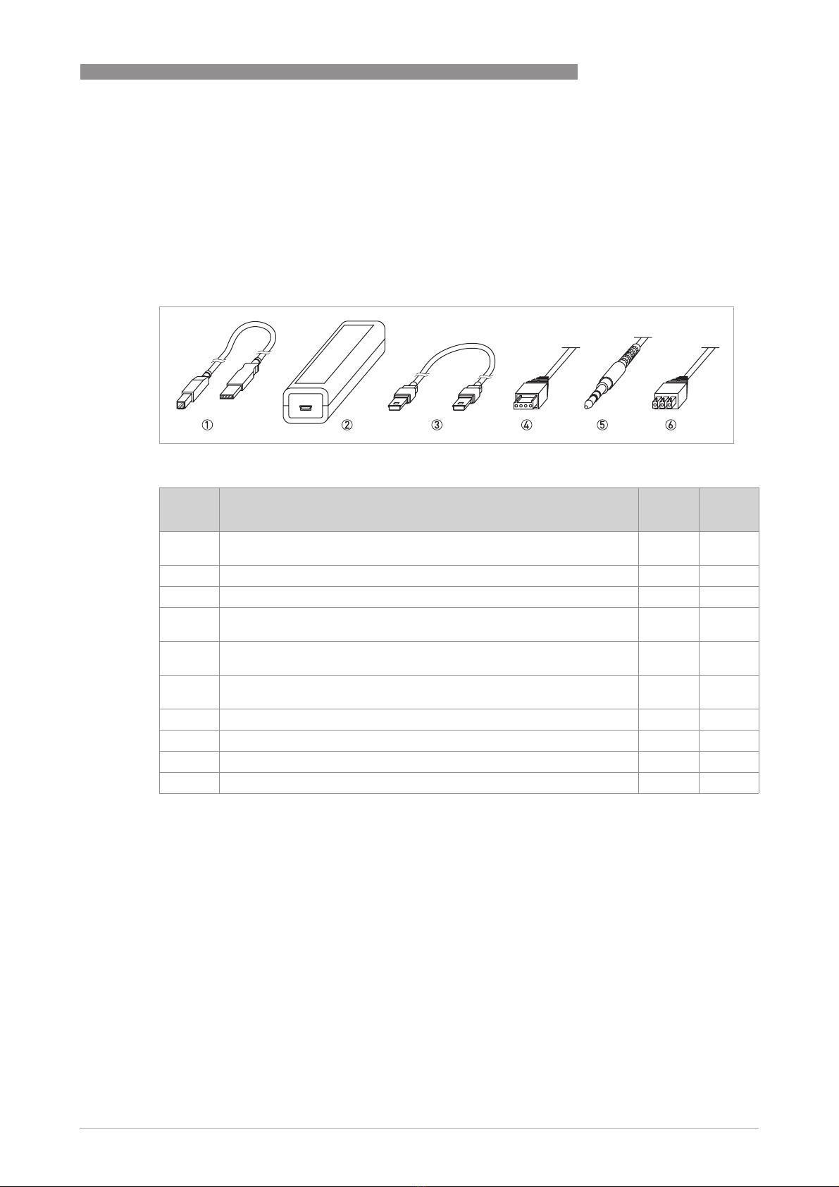
ICON-X configuration kit consists of:
•USB interface ICON-X
•USB cable (connection between PC and USB interface)
•Adapter cables (connection between USB interface and transmitter)
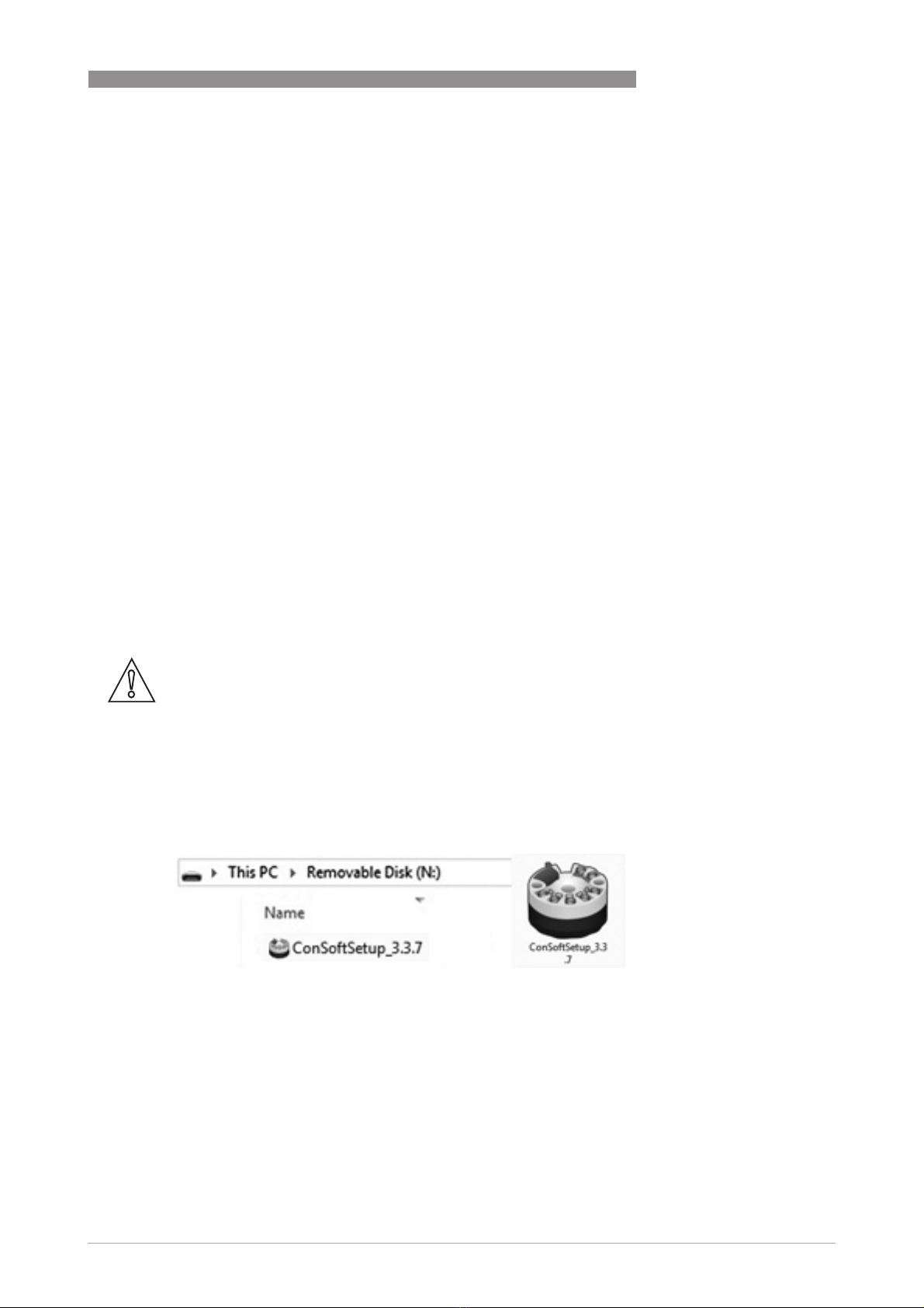
•Software and drivers on a USB memory stick
The configuration kit is compatible with Windows XP (SP3), Windows Vista, Windows 7, Windows
8, Windows 8.1 and Windows 10.
1.3 Certifications
1.3.1 EU directive compliance
The USB interface, used with the provided cables, is CE-marked and complies with the EMC
directive 2014/30/EU based on the harmonised standard EN 61326-1:2013, the ATEX-directive
2014/34/EU based on the harmonised standards EN 60079-0:2012 including A11 and EN 60079-
11:2012. and the ROHS directive 2011/65/EU, based on the harmonised standard EN 50581:2012.
For more information refer to the Declaration of Conformity, which can be found in the download
area of the manufacturer's website.
For other cables than the provided and with cable length ≥3 m / 9.8 ft. other requirements are
valid and are not covered by this EMC directive.
CAUTION!
The USB interface ICON-X is an Ex-approved product that is intended to be used for all type of
transmitters when in safe areas.
DANGER!
ICON-X is the Ex-approved connection between a PC USB interface and an INOR Ex-approved
transmitter. It may be used with non-Ex approved Inor transmitter as well. The ICON-X must not
be used in hazardous area. Consult the user instruction and Ex-certificate of the used
transmitter regarding the possibility to configure "online" if the input of the transmitter is
connected to hazardous area.
DANGER!
ICON-X contains no reparable parts. Repairing or fixing the circuit or replacing components may
impact the intrinsic safety.
CAUTION!
Only one transmitter may be connected at a time.

1
CONFIGURATION KIT
4
INOR TRANSMITTERS
www.inor.com 07/2018 - 4006932901 - AD ICON-X ConSoft R01 en
1.3.2 Ex approvals
USA and Canada:
EX-approvals according to: FM 3600, ANSI/ISA 60079-0, CAN/CSA C22.2 No. 0,
CAN/CSA C22.2 60079-0, FM 3610, ANSI/ISA 60079-11, CAN/CSA C22.2 60079-11
See also "Special conditions for safe use" in the Ex certificates in the download area of the
manufacturer's website.
1.4 Scope of delivery
1.5 Nameplate
ATEX KIWA 16ATEX0011X II (1) G [Ex ia Ga] IIC
IECEx IECEx KIWA 16.0005X [Ex ia Ga] IIC
USA FM18US0117X AIS CL I, Div 1 and 2, GP A-D,
CL I, Zn 0, 1 and 2, [AEx/Ex ia Ga] IIC
Canada FM18CA0056X
Figure 1-1: Scope of delivery
1 USB communication cable (connection between PC and USB interface)
2 USB interface
3 Mini USB to Mini USB adapter (USB interface to transmitter)
4 Mini USB to four pole rectangular connector (USB Interface to transmitter)
5 Mini USB to 3.5 mm tele plug connector (USB Interface to transmitter)
6 Mini USB to three pole rectangular connector (USB Interface to transmitter)
1 PN = Part number
SN = Serial number (yyww = year and week of manufacturing)
PO = Batch number
PN: 70USBIX001
SN: Nyyww.xxxxxx
PO: ZZZZZZZZZ
PO Box 9125
SE-200 39 Malmö
SWEDEN
0539 II (1)G [Ex ia Ga] IIC
KIWA 16ATEX0011X
IECEx KIWA 16.0005X
www.inor.com
USA FM18US0117X
Canada FM18CA0056X
AIS CL I, Div 1 and 2, GP A-D,
CL I, Zn 0, 1 and 2 [AEx/Ex ia Ga] IIC
WARNING: SUBSTITUTION OF COMPONENTS MAY IMPAIR INTRINSIC SAFETY
Per Control Drawing
No. 4006801801
Um 250 V AC/DC
0 Ta +50 °C

CONFIGURATION KIT
1
5
INOR TRANSMITTERS
www.inor.com07/2018 - 4006932901 - AD ICON-X ConSoft R01 en
1.6 Technical data
Operating conditions
Ambient temperature 0...+50°C / +32...+122°F
Storage temperature -20...+70°C / -4...+158°F
Humidity (non-condensing) 0...90% RH
Installation
Installation For detailed information, refer to chapter "Installation".
Dimensions USB interface Length: 114 mm / 4.49"; width: 36 mm / 1.42" ; heigth:
26 mm / 1.02"
Electrical connection
Power supply PC's USB port; 5 VDC; 74 mA max.
Galvanic isolation 1500 VAC
Input (PC to USB interface) USB cable type A to type B
Output (USB interface to transmitter) Changeable adapter cables
System requirements
Windows Windows XP (SP3), Vista, 7, 8, 8.1 or 10
Display resolution Minimum 800x600
Free hard disk space 185 MB
PC Port 1x USB 1.1 or higher port type A
Ex parameters
Comm.port (PC connection) Um = Vmax : 250 V AC/DC
Output port (to transmitter) Uo = Voc : 9.4 VDC
Io = Isc : 96 mA
Po : 680 mW

2
INSTALLATION
6
INOR TRANSMITTERS
www.inor.com 07/2018 - 4006932901 - AD ICON-X ConSoft R01 en
2.1 General safety notes
2.2 Safety Diagram
2.3 Installation of USB interface drivers
Before you can use the USB interface you must install the USB drivers on your PC. The setup file
includes drivers for the USB interface and can be installed manually when running the setup file.
The drivers can also be installed automatically by using Windows Update if the computer
supports this function.
For detailed information refer to section "Installation guide for ConSoft and USB-Interface
drivers".
All software, USB drivers and installation guides can also be downloaded from the website.
CAUTION!
The USB interface ICON-X is an Ex-approved product that is intended to be used for all type of
transmitters when in safe areas.
DANGER!
The transmitter's communication port (USB connection) may only be connected to the certified
ICON-X interface. When the ICON-X is connected, the temperature transmitter shall be outside
of the hazardous area; a connected sensor may be located in the hazardous area.
1 Hazardous Area
2 Safe Area
3 Temperature Sensor
4 Temperature Transmitter
5 ICON-X USB interface
6 Ex-approved Power Supply/ Zener barrier
7 PC
ICON-X

INSTALLATION
2
7
INOR TRANSMITTERS
www.inor.com07/2018 - 4006932901 - AD ICON-X ConSoft R01 en
2.4 Installation of configuration software ConSoft
All necessary software for configuration are included on the memory stick or can be downloaded
from the website of the manufacturer.
For detailed information refer to section "Installation guide for ConSoft and USB-Interface
drivers".
All software, USB drivers and installation guides can also be downloaded from the website.
2.5 Description of USB interface ICON-X
The USB interface ICON-Xis powered from the PC´s USB port. There are three LED indicators on
the USB interface: "USB", "PC" and "DEV". They are indicators to make the understanding of the
communication between PC and transmitter easier. Their functions are described below:
•"USB" LED indicates data transfer. It lights during data transfer, otherwise it is off.
•"PC" LED indicates connection between configuration program and PC. It is green only during
reading or writing to transmitter.
•"DEV" LED indicates the transmitter connection status. If it’s green, the connected
transmitter is detected by the USB interface. Flashing green indicates that the USB interface
is waiting for a new transmitter from the same product family, e.g. changing to a new device.
When it´s red no transmitter is detected by the USB interface and any sort of transmitter can
be connected to the USB interface.
2.6 Installation guide for ConSoft and USB-Interface drivers
Locate the executable setup file “ConSoftSetup”. Double click on the file to start the installation
process and follow the instructions on screen.
CAUTION!
The installation guide must be read prior to installation.

2
INSTALLATION
8
INOR TRANSMITTERS
www.inor.com 07/2018 - 4006932901 - AD ICON-X ConSoft R01 en
2.7 Troubleshooting
Error message Action
Error message "USB Interface is not installed. The
program will not work." displayed when starting
ConSoft.
Install drivers for the USB interface.
Error message "USB Interface:s hardware and/or
software should be updated." appears in ConSoft. Contact us for update of your USB interface.
Error message "Unable to install because a newer
version of this product is already installed." is
displayed during installation of ConSoft.
A newer version of ConSoft is already installed on
the computer. If you still want to install the older
version, uninstall ConSoft through "Control Panel –
Add or Remove Programs".

INSTALLATION
2
9
INOR TRANSMITTERS
www.inor.com07/2018 - 4006932901 - AD ICON-X ConSoft R01 en
2.8 Disassembling and recycling of Transmitter configuration kit ICON-X
This section describes (in short) the instructions of handling and disassembling the device when
it’s reached EOL (end of life) or is disposed of after usage. The information given is sufficient to
gather the most important parts of the device (by the end-user) which can be used for recycling.
Content of USB configuration kit ICON-X
Content of USB configuration kit ICON-XContent of USB configuration kit ICON-X
Content of USB configuration kit ICON-X
Figure 2-1:
Item No Item Name Weight
(g)
Weight
(lb)
1USB communication cable (connection between PC and USB interface
ICON-X) 42 0,09
2USB Interface ICON-X 63 0,14
3Mini USB to Mini USB adapter (USB interface ICON-X to transmitter) 17 0,04
4Mini USB to four pole rectangular connector (USB interface ICON-X to
transmitter) 23 0,05
5Mini USB to 3.5 mm tele plug connector (USB interface ICON-X to
transmitter) 19 0,04
6Mini USB to three pole rectangular connector (USB interface ICON-X to
transmitter) 24 0,05
7USB memory 15 0,03
8Case polypropylene 300 0,66
9Foam cushioning PU 20 0,04
Total 521 1,15
Table 2-1: USB configuration kit ICON-X
Item 1 and 3 - 7; sorted as electrical waste
Item 2; sorted according to chapter 2.9
Item 8 and 9; sorted as plastic.

2
INSTALLATION
10
INOR TRANSMITTERS
www.inor.com 07/2018 - 4006932901 - AD ICON-X ConSoft R01 en
2.9 Disassembling and recycling of USB Interface ICON-X
Item 2 (Table 2-1) USB Interface ICON-X consists of
DANGER!
The device MUST be disconnected from mains power before disassembling.
Wear personal protective equipment. Make sure you use a steady workplace/bench to do the
disassembly actions.
CAUTION!
Before disassembling the device, make sure you have the proper tools needed:
- Torx Screwdriver T9
- Philips head Screwdriver #1
Item No Item Name Weight
(g)
Weight
(lb)
1Label, upper side polyester 0 0
2Label, bottom side polyethylene 0 0
3General purpose ABS plastic package box (UL94-HB) 38 0,08
4PCB Glass fiber reinforced Epoxy 10,6x2,9 cmm
2
22 0,05
5Cover Screws threaded, 2 pieces (4x3/4 self-tapping oval head 19,1 mm) 2 0
6Sealing washer, 2 pieces 0 0
7PC Board Screws, 2 pieces (4x1/4 self-tapping oval head 6,4 mm) 0 0
Total 63 0,14
Table 2-2: USB configuration interface ICON-X

INSTALLATION
2
11
INOR TRANSMITTERS
www.inor.com07/2018 - 4006932901 - AD ICON-X ConSoft R01 en
USB Interface ICON-X may be separated into smaller parts.
Items are numbered according to the Table 2-2.
•Disassembling USB Interface ICON-X
Disassembling USB Interface ICON-XDisassembling USB Interface ICON-X
Disassembling USB Interface ICON-X
1. Disconnect connection to the PC (if any connected).
2. Disconnect temperature transmitter (if any connected).
3. Remove the labels (polyester and polyethylene) sorted as plastic.
4. By unscrewing of the two threaded screws (item 5) from the bottom cover of the housing, upper
part of Item 3(in Table 2) can be separated from bottom part.
5. Lift up front and rear panel of the item 3. They are sorted as plastic.
6. By unscrewing of the two threaded screws(item 7) on the PCB(item 4) separate the bottom cov-
er of the housing - Item 3 and PCB(item 4).
7. Items 1, 2 and 3 are sorted as plastic.
8. Item 4 sorted as electronic waste.
9. Item 6(Sealing washer) sorted as ordinary waste.
10. Item 5 and 7 are sorted as metal waste.
Figure 2-2: Disassembled USB interface ICON-X

2
INSTALLATION
12
INOR TRANSMITTERS
www.inor.com 07/2018 - 4006932901 - AD ICON-X ConSoft R01 en
2.10 Installation and control drawing
This drawing is property of Inor Process AB, Malmö, Sweden, without whose permission
it may not be copied, and the contents thereof must not be imparted to third party nor be
Scale:
Revision
Det.no.
Date Comment
File
Date:
Description
Quantity Document-ID
Drawing number:
General tolerance
General surface roughness Ra
SS-ISO-2768-1 m
Approved by:
Designed by:
Approved by:
Title:
Rev:
used for any unautherized purpose. Contravention will be prosecuted.
No of sheets:
Sheet:
Treatment:
Projection:
Material Article no.
Ra 3,2
1:1
2018-06-21
NH GP
4006801801_1.dwg 1
1
4006801801 1
180716 First release revision GP
Rev 1
Europe:
KIWA 16ATEX0011 X
IECEx KIWA 16.0005X
CE 0539 II (1) G [Ex ia Ga] IIC
Non Hazardous Location (Safe area) Europe:
1. The associated apparatus or intrincically safe equipment shall be approved.
2. Safety barriers must be installed in accordance with the
manufacturers instructions.
3. If the cable parameters are unknown, the following values may be
used as a guideline:
Capacitance = 200 pF/m
Inductance = 0.66 μH/m
4. If a safety barrier is used and the safety barrier requires an earth conection
then the resistance between the terminal on the safety barrier and the earth
ground shall be less than 1 ohm.
5. Do not connect any communication equipment to the communication port
of the transmitter unless area is known to be non-hazardous.
North America:
1. The configuration of the associated apparatus or intrincically safe
equipment or simple apparatus shall be approved.
2. Safety barriers must be installed in accordance with the
manufacturers instructions.
3. Installation must be accordance with the National Electrical Code
(NFPA 70, Article 500 to 510), Canadian Electrical Code (CEC)
Section 18 and ANSI/ISA-RP12.06.01
4. If the cable parameters are unknown, the following values shall be
used:
Capacitance = 200 pF/m (60pF/feet)
Inductance = 0.66 μH/m (0.20μH/feet)
5. If the safety barrier requires an earth conection then the
resistance between the terminal on the safety barrier and the earth
ground shall be less than 1 ohm.
6. Do not connect any communication equipment to the communication port
of the transmitter unless area is known to be non-hazardous.
The control equipment
connected must not
use or generate over
250 V rms or dc
Um = 250 V
Ex-document, may not be revised without approval from
the Certification Body.
1000457600 4006801801
SWEDEN Doc. type:
ZZ
USB Connection (to PC)
Um=250V50/60Hz
Transmitter
Connection
ATEX, IECEx and FM
Uo=Voc=9.4 V
Io=Isc=96 mA
Po=680 mW
Group Co=Ca Lo=La
(μF) (mH)
IIC A/B 1 1
IIB C 29 29
IIA D 300 70
Installation and control drawing
Transmitter configuration kit
ICON-X configuration kit
Specific conditions of use:
- The transmitter's communication port (USB connection) may only be
connected to the certified ICON-X interface.
When the ICON-X is connected, the temperature transmitter shall be
outside of the hazardous area; a connected sensor may be located in
the hazardous area.
- For the applicable ambient temperature range, see the sketch.
21 +
22 -
1
2
3
4
North America:
USA FM18US0117X
Canada FM18CA0056X
AIS Class I, Division 1, Division 2, Groups A, B, C, D;
Class I, Zone 0, Zone 1, Zone 2 [AEx / Ex ia Ga] IIC
ICON-X configuration kit
Power supply/4-20 mA, 2-Wire loop (-)
(+) ENTITY PARAMETERS
Voc=Uo ≥ 30 V
Isc=Io ≥ 100 mA
Po ≥ 0.9 W
Ca=Co Ci + Ccable
La=Lo Li + Lcable
Associated apparatus
0°C≥Ta≥+50°C
Hazardous (Classified)
Location
1
432
6
7
Sensor
(RTD, T/C etc.)
5
+
-
Sensor
(RTD, T/C etc.)
The topside
The bottom side
(Power supply is optional for configuration with ICON-X)

NOTES
3
13
INOR TRANSMITTERS
www.inor.com07/2018 - 4006932901 - AD ICON-X ConSoft R01 en

3
NOTES
14
INOR TRANSMITTERS
www.inor.com 07/2018 - 4006932901 - AD ICON-X ConSoft R01 en

NOTES
3
15
INOR TRANSMITTERS
www.inor.com07/2018 - 4006932901 - AD ICON-X ConSoft R01 en

Inor North America
7 Dearborn Road
Peabody, MA 01960
United States
Phone: +1 978 826 6900
Fax: +1 978 535 1720
Web: www.inor.com
Inor Transmitter GmbH
Am See 24
D-47279 Duisburg
Germany
Phone: +49-(0)203 7382 762 0
Fax: +49-(0)203 7382 762 2
Web: www.inor-gmbh.de
The current list of all INOR contacts and addressescan be found at:
www.inor.com
Inor Process AB
PO Box 9125
SE-200 39 Malmö
Sweden
Phone: +46-(0)40-312 560
Fax: +46-(0)40-312 570
Subsidiaries
Inor Transmitter Oy
Unikkotie 13
FI-01300 Vantaa
Finland
Phone: +358-(0)10-4217900
Fax: +358-(0)10-4217901
E-mail: myyn[email protected]
Web: www.krohne-inor.fi
©INOR 07/2018 - 4006932901 - AD ICON-X ConSoft R01 en
Table of contents
Other INOR Transmitter manuals

INOR
INOR APAQ-HRF User manual

INOR
INOR APAQ C130 TC User manual

INOR
INOR IPAQ-4L User manual

INOR
INOR IPAQ C520 Wiring diagram

INOR
INOR IPAQ C520 User manual

INOR
INOR IPAQ-LX User manual

INOR
INOR APAQ C130 User manual

INOR
INOR IPAQ C330 Series User manual

INOR
INOR IPAQ R202 User manual

INOR
INOR IPAQ-L User manual