Inspire M2 Supplement

ASSEMBLY & OPERATION MANUAL
RECORD SERIAL NUMBER HERERECORD SERIAL NUMBER HERE
www.inspirefitness.netwww.inspirefitness.net by Health In Motion LLC Mar. 2010

CONGRATULATIONS… You’ve just taken the first step to a healthier
and stronger body. This home gym by Inspire offers the key to unlocking
your body’s potential. Regular strength training on a home gym has been
shown to deliver a host of benefits including: increased muscle tone,
decreased body fat, improved energy levels, a reduction in stress, and
improved cardiac output. Once again, congratulations, you are on your way
to improving your self image, overall health and quality of life.
BEFORE ASSEMBLING YOUR HOME GYM
IMPORTANT: Read this entire manual before attempting to build or use
this machine. This manual contains step by step instructions for proper
assembly.
Use the parts list included in this manual to verify that all parts are
accounted for before assembly. If any parts are missing, contact the retailer
of this home gym for replacement parts. Or, call Inspire at 714-738-1729
Make sure that adequate room has been cleared before attempting to build
your home gym. A rubber mat is recommended for use under your home
gym to protect wood flooring or carpeting from damage during assembly
and usage.
This home gym is intended for indoor use only. In addition, garages and
screened in porches are not recommended due to high humidity or dust.
Certain parts including guide rods can form rust in a humid environment,
resulting in impaired function.
Service of your home gym should only be preformed by an authorized
INSPIRE retailer. Service preformed by anyone else can result in loss of
warranty. If you need help finding an authorized retailer, please contact us
directly:
Inspire Fitness
637 S. State College Blvd.
Fullerton, CA 92831
Ph: 714-738-1729 or 877-738-1729
Fx: 714-738-1728
www.inspirefitness.net

TABLE OF CONTENTS
Section Description……………………………………………………. Page
Important Safety Instructions………………………………………. 1
Tools Required………………………………………………………………… 1
Parts List…………………………………………………………………………. 2
Hardware List…………………………………………………………………. 2
Hardware Chart …………………………………………………………….. 3
Cable Chart ……………………………………………………………………. 5
Assembly Instructions……………………………………………………. 6
Decal Reference……………………………………………………………… 26
Decal Placement……………………………………………………………… 28
Accessories……………………………………………………………………… 29
General Maintenance Information…….…………………………… 30
Maintenance Schedule…….……………………………………………… 31
Limited Warranty…………………………………………………………….. 32

IMPORTANT SAFETY INSTRUCTIONS
Please read this entire manual and familiarize yourself with all decals and
warnings before using this home gym.
• WARNING! It is necessary to inspect this home gym regularly to
maintain safety and proper function. Please use the maintenance schedule
included towards the back of this manual. Immediately replace any and all
defective or worn parts. Pay special attention to moving parts such as the
cables and pulleys and connections to accessories. See General
Maintenance section for complete details.
• Use this home gym for its intended purpose as described in this Operation
Manual or the exercise chart. Do not use attachments not recommended by
the manufacturer.
• Do not hang from press arm. The press arm is not designed to
support human weight.
• Make sure bystanders are at least 5 feet away from the home gym while
it is in use.
• Keep children off the home gym at all times.
• Keep the home gym away from walls and clear of any obstructions and
furniture.
• Stop immediately if you experience shortness of breath, pain, or dizziness
during your workout. Inspire strongly recommends consulting your doctor
before starting an exercise program.
TOOLS REQUIRED FOR ASSEMBLY
• Standard socket set (including 9/16” and 1/2” sockets)
• 1/2” wrench
•9/16” wrench
•
3/4" wrench
• Tape Measure
• Rubber Mallet
• Adjustable wrench
PAGE 1

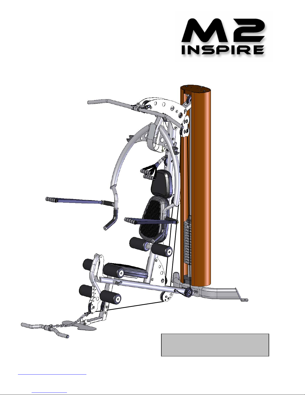
M2 PARTS & HARDWARE LIST
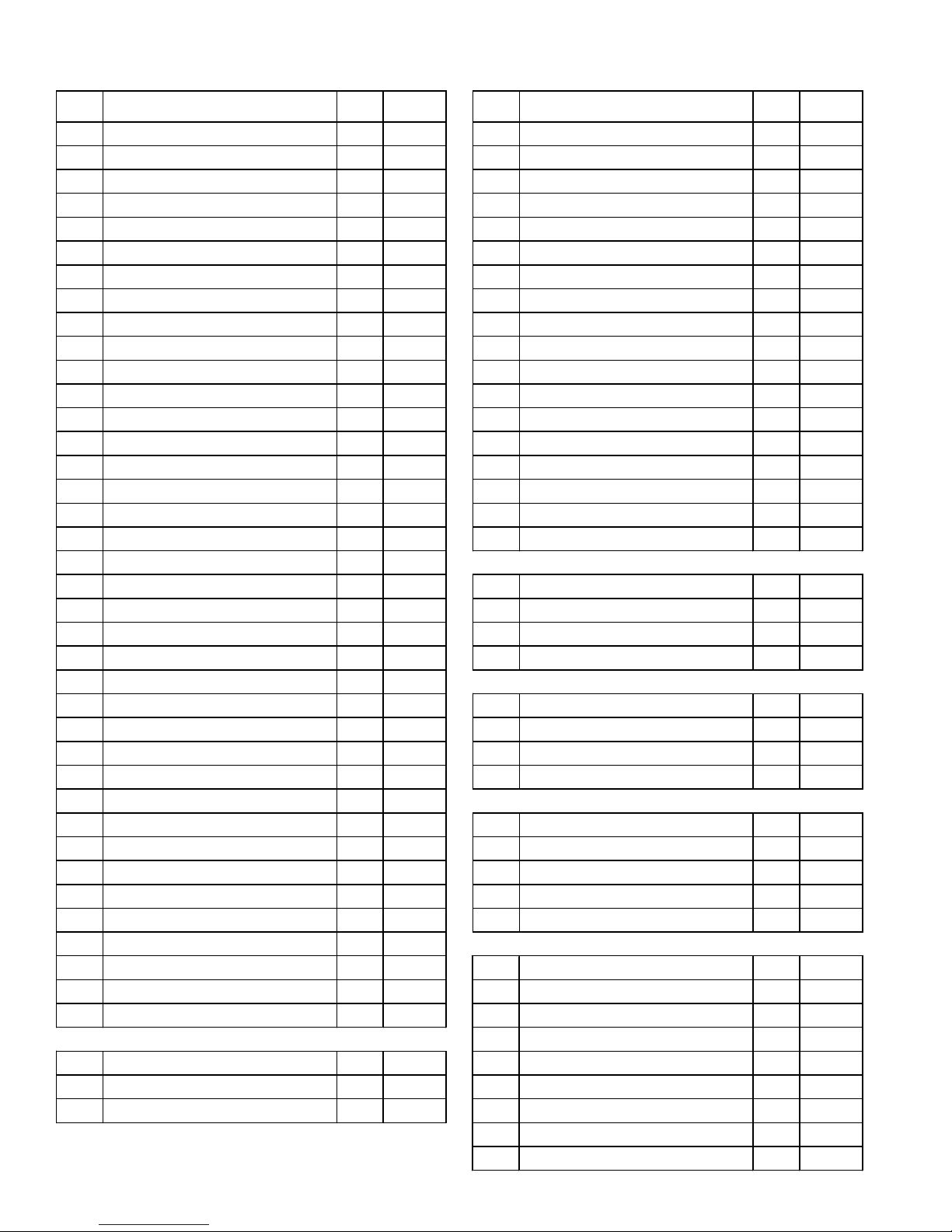
Item Parts Description Qty QtyRec'd Item Hardware Description Qty QtyRec'd
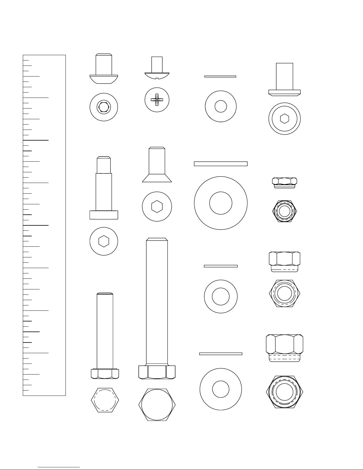
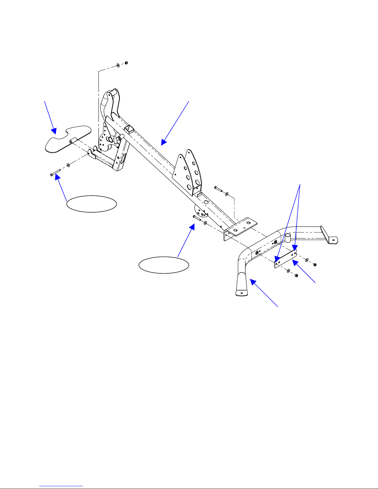
1 Base Beam 1 1 Bolt, 1/4-20 x 3/8" L (Phillips head) 1
2 Rear Base 1 2 Bolt, 1/4-20 x 3" L (Button Head) 1
3 Backing Plate 1 3 Bolt, 5/16-18 x 1-1/4" L (Shoulder) 3
4 Foot Plate 1 4 Bolt, 3/8x16 x 1" L (Flat Head) 8
5 Main Upright 1 5 Bolt, 3/8-16 x 1/2" L (Button Head) 2
6 Top Beam Plate 2 6 Bolt, 3/8-16 x 1" L 6
7 Press Arm Mount 1 7 Bolt, 3/8-16 x 1 3/4" L 7
8 Press Arm Cover Plate 1 8 Bolt, 3/8-16 x 2" L 4
9 Press Arm Bearing Assembly 2 9 Bolt, 3/8-16 x 2 1/2" L 1
10 Press Arm Assembly 1 10 Bolt, 3/8-16 x 2 3/4" L 2
11 Backpad Tilt Frame 1 11 Bolt, 3/8-16 x 3" L 5
12 Lat Bar Holder 2 12 Bolt, 3/8-16 x 3 3/4" L 8
13 Guide Rod 2 13 Bolt, 3/8-16 x 4" L 6
14 Shroud Plate 1 14 Bolt, 3/8-16 x 4 3/4" L 1
15 Shroud Plate Assembly 1 15 Bolt, 3/8-16 x 5" L 1
16 Floating Pulley Plate 2 16 Bolt, 3/8-16 x 5 3/4" L 1
17 Floating Pulley Bracket 1 17 Bolt, 1/2-13 x 6" L 1
18 Top Weight/Selector Stem 1 18 Setscrew, 1/4-20 x 3/16" long 2
19 Weight Stack Riser 2
20 Weight Stack Number 1 19 1/4" Washer 1
21 Rubber Donut 2 20 3/8" Washer 65
22 Roller Tube 3 21 3/8" Washer, small OD 6
23 Covered Foam Roller 6 22 1/2" Washer 2
24 Aluminum Endcap 6
25 Large Plastic Washer 6 23 1/4-20 Flat Head Nut 1
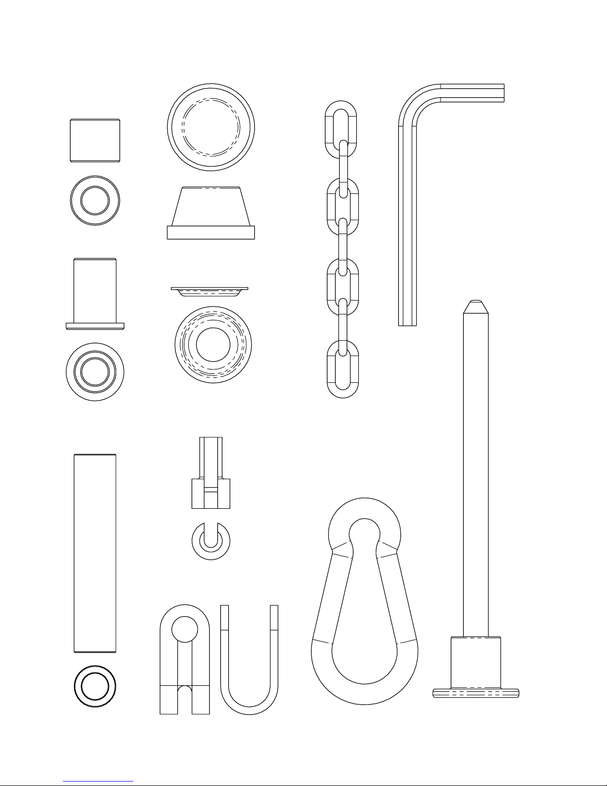
26 Seat Stem 1 24 5/16-18 Locknut 3
27 Seat Base 2 25 3/8-16 Locknut 36
28 Head Pad 1 26 1/2-13 Locknut 1
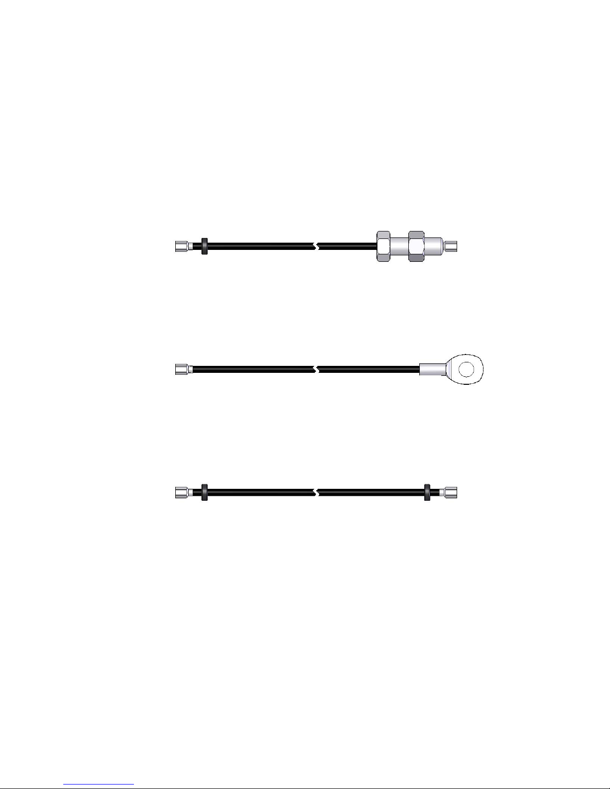
29 Upper Cable 1
30 Middle Cable 1 27 Spacer Tube, 3" Long 1
31 Lower Cable 1 28 Step Spacer, 1" Long 8
32 D handle/Ab Strap 2 29 Step Spacer, 1/2" Long 2
33 Ankle Strap 1 30 Barrel Spacer, 1" Long 2
34 Revolving Aluminum Lat Bar 1 31 Barrel Spacer, 5/8" Long 2
35 Revolving Aluminum Curl Bar 1
36 Fabric Shroud 1 32 Cable Adapter 1
37 Guide Rod Lube 2 33 "U" Bracket Cable End 3
38 Touch-up Paint 1 34 Cable Ball 3
35 Spring Clip 4
39 3 1/2" Pulley 14 36 Chain 1
40 4 1/2" Pulley 2 37 Weight Pin 1
41 4 1/2" Wide Pulley 1 38 3 mm Wrench 1
39 5 mm Wrench 1
40 6 mm Wrench 1
PAGE2

3/8" DIA. Bolt 5/16"DIA. Shoulder Bolt Button Head Bolt
3/8" Washer 3/8" Washer Sm. O.d. 1/2" Washer 1/4" Washer
1/2" Locknut 3/8" Locknut 5/16" Locknut Flat Head Nut
1/2" DIA. Bolt 3/8"DIA.Flat Head Bolt Phillips Head Screw
ACTUAL PARTS MAY BE SMALLER OR LARGER THAN SHOWN
1" 2" 3" 4" 5" 6" 7"
HARDWARE CHART
PAGE 3

"U" Bracket Cable End Cable Adaptor Hat Washer Dome Cap
Spring Clip
Weight Pin Allen Wrench
Spacer Tube Step Spacer Barrel Spacer
Chain
ACTUAL PARTS MAY BE SMALLER OR LARGER THAN SHOWN
HARDWARE CHART
PAGE 4

LOWER CABLE
MIDDLE CABLE
UPPER CABLE
CABLE CHART
PAGE 5

ASSEMBLY INSTRUCTIONS
PAGE 6

FootPlate MainBase
1- 3” Hex Bolt
2 - 3/8” Small OD Washers
1 - 3/8” Lock Nut
Do Not Over Tighten
2 - 3” Hex Bolts
4 - 3/8” Flat Washers Backing Plate
2 - 3/8” Lock Nuts
Rear Base
STEP 1: Attach Rear Base to Main Base using: Two (3/8” x 3” Hex Bolt)
Four(3/8”FlatWashers)
Note: Wrench tighten now Two (3/8” Lock Nuts)
Note: Use outside holes in Step 1 One (8 ¼” Backing Plate)
STEP 2: Attach Foot Plate to Main Base using: One (3/8” x 3” Hex Bolt)
Note: Wrench tighten now but Two (3/8” Small OD Washers)
do not over tighten. One (3/8” Lock Nut)
Foot plate must flip up easily
Page 7
STEP 1
STEP 2
NOTE: Use
Outside Holes
in Ste
p
1.

Guide Rods
Shroud Plate
Holes must line up
2 - 3 ¾” Hex Bolts
4 - 3/8” Flat Washers
2 - 3/8” Lock Nuts
FINGER TIGHTEN ONLY!
STEP 3: Attach Guide Rods to Rear Base using: Two (3/8” x 3 ¾” Hex Bolts)
Note: Finger tighten only Four (3/8” Flat Washers)
Note: If these bolts do not go in smoothly Two (3/8” Lock Nuts)
Loosen bolts from step 1.
STEP 4: Slide Shroud Plate down Guide Rods onto Rear Base. Make sure that center hole in
Shroud Plate lines up with hole between Guide Rods in Main Base.
Page 8
STEP 3
STEP 4

IMPORTANT!
Guide Rods must be
2 - 1 ¾” Hex Bolts in Front of plate.
4-3/8” Flat Washers
2- 3/8” Lock Nuts
FINGER TIGHTEN ONLY
Main Upright
2 - 4” Hex Bolts
4 - 3/8” Flat Washers
2 - 3/8” Lock Nuts
FINGER TIGHTEN ONLY
Step 5: Attach Main Upright to Main Base using: Two (3/8” x 4” Hex Bolts)
Note: Finger Tighten Only Four (3/8” Flat Washers)
Two(3/8”LockNuts)
Step 6: Attach Guide Rods to Main Upright using: Two (3/8” x 1 ¾” Hex Bolts)
Note: Finger Tighten Only Four (3/8” Flat Washers)
Two(3/8”LockNuts)
Page 9
STEP 5
STEP 6

Note: Attach left and right top beams with “Inspire” logo facing out.
Right Top Beam Plate Left Top Beam Plate
1” Bolt
1” Bolt
2 - 4” Hex Bolts
2-1”HexBolts
6-3/8”FlatWashers
2-3/8”LockNuts
FINGER TIGHTEN ONLY
Press Arm Mount
Step 7: Attach Left and Right Top Beam PlatestoMainUprightusing:
Two (3/8” x 4” Hex Bolts)
Two (3/8” x 1” Hex Bolts)
Six (3/8” Flat Washers)
Note: Finger Tighten Only Two(3/8”LockNuts)
NOTES: Hang Press Arm Mount from Top Beam Plates as Plates are attached.
Page 10
STEP 7

Press Arm Bearings
Use Small OD Washers on the
Outside of the Press Arm Bearings
4 – 1” Hex Bolts
4 – 3/8” Small OD
Washers
4 – 3/8” Flat Washers
4 – 3/8” Lock Nuts
2 – ½” Button Head Bolts
2 – 3/8” Flat Washers
Press Arm Mount
Step 8: Attach Press Arm Bearings to Top Beam Plates using:
Note: Finger Tighten Only Four (1" Hex Bolts)
Four (3/8” Small OD Washers)
Four (3/8” Flat Washers)
Four (3/8” Lock Nuts)
Step 9: Attach Press Arm Mount to Press Arm Bearings Using:
Note: Finger Tighten Only Two (1/2” Button Head Bolts)
Two(3/8”FlatWashers)
Page 11
STEP 8
STEP 9

Install Four Pulleys
PULLEY 1
1 - 3 ¾” Hex Bolt
2 - 1” Step Spacers
1-3/8”LockNut 4½”Pulley
1 - 2” Hex Bolt
2 - 3/8” Flat Washers
1 - 3/8” Lock Nut
PULLEY2
3½”Pulleys
PULLEY3
PULLEY4
2 - 3 ¾” Hex Bolts
4 - 1” Step Spacers
2 - 3/8” Lock Nuts
Step 10: Attach Pulley 1 to Main Upright using: One (4 ½” Pulley)
One (3 ¾” Hex Bolt)
Two(1”StepSpacers)
One(3/8”LockNut)
Attach Pulley 2 to Main Upright using: One (3 ½” Pulley)
One (2” Hex Bolt)
Two(3/8”FlatWashers)
One(3/8”LockNut)
Attach Pulleys 3 & 4 to Main Upright using: Two (3 ½” Pulleys)
Two (3 ¾” Hex Bolts)
Four(1”StepSpacers)
Page 12 Two (3/8” Lock Nuts)
STEP 10

STEP 11
STEP 12
STEP 13
2 – Lat Bar Holders
1 – 4 ¾” Hex Bolt
1 – 3” Spacer Tube
2 – 3/8” Flat Washers
1 – 3/8” Lock Nut
1 – 4 ½” Wide Pulley Pulley 6
1 – 4” Hex Bolt
2 – 5/8” Barrel Spacers
2 – 3/8” Flat Washers
1 – 3/8” Lock Nut Pulley 5
1 – 3 ½” Pulley
1–4”HexBolt
2 – 1” Barrel Spacers
2 – 3/8” Flat Washers
1 – 3/8” Lock Nut
Step 11: Attach Pulley 5 to Top Beam using: One (3 ½” Pulley)
One (3/8” x 4” Hex Bolt)
Note: Finger Tighten Only Two(1”BarrelSpacers)
Two(3/8”FlatWashers)
One(3/8”LockNut)
Step 12: Attach Pulley 6 to Top Beam using: One (4 ½” Wide Pulley)
One (3/8” x 4” Hex Bolt)
Note: Finger Tighten Only Two(5/8”BarrelSpacers)
Two(3/8”FlatWashers)
One(3/8”LockNut)
Step 13: Attach Lat Bar Holders to Top Beam using: Two (Lat Bar Holders)
One (3/8” x 4 ¾” Hex Bolt)
One(3”SpacerTube)
NOTE: Tighten all bolts in steps 8 – 13 Now. Two (3/8” Flat Washers)
Do Not Over Tighten One (3/8” Lock Nut)
Page 13

Install Six Pulleys &
One Cable Retaining Bolt
TIGHTEN THESE BOLTS NOW
1 – 4 ½” Pulley
1–3¾”HexBolt
PULLEY 7 2 – 1” Step Spacers
1–3/8”LockNut
1 – 3 ½” Pulley
1 – 2” Hex Bolt
2 – 3/8” Flat Washers
1 – 3/8” Lock Nut 1 – 3 ½” Pulley
1–1¾”HexBolt
2 – 3/8” Flat Washers
1–3/8”LockNut
PULLEY 12
PULLEY 8
PULLEY 9
PULLEY 10
NOTE: If you purchased leg press option,
refer to leg press owners
PULLEY11 manual before attaching pulley 11
CABLE RETAINING BOLT
1 – 2 ¾” Hex Bolt 1 – 3 ½” Pulley 1 – 3 ½” Pulley 1 – 3 ½” Pulley
2 – 3/8” Flat Washers 1 – 2 ¾” Hex Bolt 1 – 2” Hex Bolt 1 – 5 ¾” Hex Bolt
1 – 3/8” Lock Nut 2 – ½” Step Spacers 2 – 3/8” Flat Washers 2 – 3/8” Flat Washers
1 – 3/8” Lock Nut 1 – 3/8” Lock Nut 1 – 3/8” Lock Nut
Step 14:
Attach Pulley 7 using: One (3 ¾” Hex Bolt) Attach Pulley 10 using: One (2” Hex Bolt)
Two (1” Step Spacers) Two (3/8” Flat Washers)
One (3/8” Lock Nut) One (3/8” Lock Nut)
Attach Pulley 8 using: One (2” Hex Bolt) Attach Pulley 11 using: One (5 ¾” Hex Bolt)
Two (3/8” Flat Washers) Two (3/8” Flat Washers)
One (3/8” Lock Nut) One (3/8” Lock Nut)
Attach Pulley 9 using: One (2 ¾” Hex Bolt) Attach Pulley 12 using: One (1 ¾” Hex Bolt)
Two (½” Step Spacers) Two (3/8” Flat Washers)
One (3/8” Lock Nut) One(3/8”LockNut)
Attach Cable Retaining Bolt using: One (2 ¾” Hex Bolt)
Two (3/8” Flat Washers)
Page 14 One (3/8” Lock Nut)
STEP 14

NOTE: Once Assembled, slide rubber
washer against plastic ball
1 – Plastic Ball
1 – Cable “U” Bracket
1 – 1 ¼ “ Shoulder Bolt
1 – Spring Clip
1–5/16”LockNut
Pulley 13 NOTE: CABLE GOES INSIDE FRAME TUBE
Press Arm Mount
2 – 3 ½” Pulleys Pulley 14
2 – 3” Hex Bolts
4 – 3/8” Flat Washers
2 – 3/8” Lock Nuts
Step 15:
Begin by running upper cable from back of machine to front
as shown in the diagram. Next, slide pulleys 13 & 14 into the
Press Arm Mount as cable is routed. Secure Press Arm Pulleys using:
Two (3” Hex Bolts)
Wrench Tighten Now. Four (3/8” Flat Washers)
Two(3/8”LockNuts)
Step 16: Assemble Cable End by sliding one plastic ball onto the end of the cable. Next slide the
cable end into the side of the cable “U” bracket. Finally, attach spring clip to “U” bracket using a
1 ¼” shoulder bolt and 5/16” lock nut. Wrench Tighten Now.
Page 15
STEP 16
STEP 15

1 – Floating Pulley Bracket
1 – 3 ½” Pulley 2 – Floating Pulley Plates
1 – Cable Adapter 2 – 3 ½” Pulleys
1 – 2” Hex Bolt 2 – 1 3/4” Hex Bolts
2 – 3/8” Flat Washers 4 – 3/8” Washers
1 – 3/8” Lock Nut 2 – 3/8” Lock Nuts
Pulley 16
Pulley 15
Pulley Plate
Pulley 17
Pulley 11
1–5”HexBolt
3 – 3/8” Flat Washers
1 – 3/8” Lock Nut
Step 17: Attach the Middle Cable to the Main Base using: One (3/8” x 5” Hex Bolt)
Finger Tighten Only Three (3/8” Flat Washers)
One(3/8”LockNut)
Step 18: Assemble the Pulley Plates using: Two (Floating Pulley Plates)
WrenchTightenNow Two(3½”Pulleys)
Two(1¾”HexBolts)
Four(3/8”FlatWashers)
Two(3/8”LockNuts)
Step 19: Attach Middle Cable to Floating Pulley Bracket using: One (Cable Adapter)
WrenchTightenNow One(3½”Pulley)
One(3/8”x2”HexBolt)
Two(3/8”FlatWashers)
Page 16 One (3/8” Lock Nut)
STEP 17
STEP 18
STEP 19

1 – Plastic Ball
1 – Cable “U” Bracket
1 – 1 ¼ “ Shoulder Bolt
1 – Spring Clip
1 – 5/16” Lock Nut
1 – Plastic Ball
1 – Cable “U” Bracket
1 – 1 ¼ “ Shoulder Bolt
1 – Spring Clip
1 – 5/16” Lock Nut
Route Lower Cable
Pulley 10
Cable Retainer Pin
Step 20: Assemble Cable End as done
in step 16 using: One (Plastic Ball)
Wrench Tighten Now One (Cable “U” Bracket)
One(1¼”ShoulderBolt)
One(SpringClip)
One(5/16”LockNut)
Step 21: Route Lower Cable from top to bottom
NOTE: Make sure cable is routed between pulley 10 and cable retainer pin.
Step 22: Assemble Cable End as done
in step 16 using: One (Plastic Ball)
Wrench Tighten Now One (Cable “U” Bracket)
One(1¼”ShoulderBolt)
One(SpringClip)
One(5/16”LockNut)
Page 17
STEP 20
STEP 22
STEP 21
Other manuals for M2
1
Table of contents
Other Inspire Home Gym manuals

Inspire
Inspire M1 Supplement

Inspire
Inspire FT2 Supplement

Inspire
Inspire SCS-1 Installation and operating instructions

Inspire
Inspire CR 2 User manual

Inspire
Inspire M1 Supplement

Inspire
Inspire M2 Supplement

Inspire
Inspire FT1 Supplement

Inspire
Inspire M5 Supplement

Inspire
Inspire M3 Supplement

Inspire
Inspire M5 User manual
Popular Home Gym manuals by other brands

XMark Fitness
XMark Fitness XM-9050 owner's manual

Sunny Health & Fitness
Sunny Health & Fitness SF-RW5854 user manual

ICON Health & Fitness
ICON Health & Fitness PRO-FORM 550R user manual

Stamina
Stamina Active Aging EasyRow owner's manual

Weider
Weider 9250 Manuel de l'utilisateur

Weider
Weider Muscle 129 owner's manual