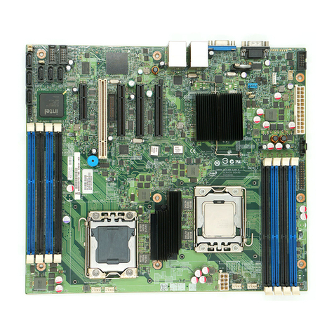
Intel® Server Board M50CYP2SB Family Technical Product Specification
7
9.3.3 Dual Monitor Support...................................................................................................................................................90
9.4 Intel® Ethernet Network Adapter for OCP* Support........................................................................................ 90
10. Intel® Light Guided Diagnostics............................................................................................................................. 91
10.1 Post Code Diagnostic LEDs........................................................................................................................................ 92
10.2 System ID LED ................................................................................................................................................................. 92
10.3 System Status LED......................................................................................................................................................... 92
10.4 BMC Boot / Reset Status LED Indicators .............................................................................................................. 94
10.5 Processor Fault LEDs....................................................................................................................................................95
10.6 Memory Fault LEDs .......................................................................................................................................................95
10.7 Fan Fault LEDs.................................................................................................................................................................96
11. System Software Stack............................................................................................................................................ 97
11.1 Hot Keys Supported During POST.......................................................................................................................... 98
11.1.1 POST Logo/Diagnostic Screen ................................................................................................................................. 98
11.1.2 BIOS Boot Pop-Up Menu ............................................................................................................................................ 98
11.1.3 Entering BIOS Setup ..................................................................................................................................................... 99
11.1.4 BIOS Update Capability............................................................................................................................................... 99
11.2 Field Replaceable Unit (FRU) and Sensor Data Record (SDR) Data........................................................... 99
11.2.1 Loading FRU and SDR Data........................................................................................................................................99
12. System Security ...................................................................................................................................................... 100
12.1 Password Protection.................................................................................................................................................. 100
12.1.1 Password Setup ........................................................................................................................................................... 101
12.1.2 System Administrator Password Rights ............................................................................................................ 101
12.1.3 Authorized System User Password Rights and Restrictions..................................................................... 102
12.2 Front Panel Lockout................................................................................................................................................... 102
12.3 Intel® Platform Firmware Resilience (Intel® PFR)............................................................................................ 102
12.4 Intel® Total Memory Encryption (Intel® TME) .................................................................................................. 103
12.5 Intel®Software Guard Extensions (Intel®SGX)................................................................................................. 103
12.6 Trusted Platform Module (TPM) Support ......................................................................................................... 104
12.6.1 Trusted Platform Module (TPM) Security BIOS.............................................................................................. 105
12.6.2 Physical Presence ....................................................................................................................................................... 105
12.6.3 TPM Security Setup Options .................................................................................................................................. 105
12.7 Intel® CBnT –Converged Intel® Boot Guard and Trusted Execution Technology (Intel® TXT) ... 106
12.8 Unified Extensible Firmware Interface (UEFI) Secure Boot Technology.............................................. 106
13. Server Board Configuration and Service Jumpers.......................................................................................... 107
13.1 BIOS Default Jumper (BIOS DFLT –J70)........................................................................................................... 107
13.2 Password Clear Jumper (PASSWD_CLR –J29) .............................................................................................. 108
13.3 Intel® Management Engine (Intel® ME) Firmware Force Update Jumper
(ME_FRC_UPDT –J22)............................................................................................................................................... 108
13.4 BMC Force Update Jumper (BMC FRC UPD - J20)........................................................................................ 109
13.5 BIOS SVN Downgrade Jumper (BIOS_SVN_DG –J71)................................................................................ 110
13.6 BMC SVN Downgrade Switch (BMC_SVN_DG –S5)...................................................................................... 111
Appendix A. Getting Help ........................................................................................................................................ 112
