manuals.online logo
Brands
  1. Home
  2. •
  3. Brands
  4. •
  5. Intel
  6. •
  7. Server
  8. •
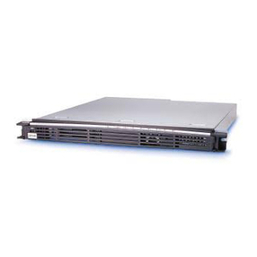
  9. Intel ISP1100 - Server Platform - 0 MB RAM User manual

Intel ISP1100 - Server Platform - 0 MB RAM User manual

SCSI Cable Option Kit
Installation Guide for
Intel®ISP1100 Internet Server
The most current version of this document and other documents relating to the
Intel®ISP1100 Internet Server can be found at http://www.intel.com/isp.
Copyright © 2000 Intel Corporation.All rights reserved. No part of this document
may be copied, or reproduced in any form, or by any means without prior written
consent of Intel.
Intel Corporation (Intel) makes no warranty of any kind with regard to this material,
including, but not limited to, the implied warranties of merchantability and fitness for a
particular purpose. Intel assumes no responsibility for any errors that may appear in
this document. Intel makes no commitment to update nor to keep current the informa-
tion contained in this document.
† Third-party brands and trademarks are the property of their respective owners.
February 29, 2000
Revision 1.0
Document Number:A16589-001
Intel ISP1100 Internet Server SCSI Cable Kit 1
Introduction
This document explains how to install the SCSI cable kit, which is used with third-
party SCSI adapters in the Intel ISP1100 Internet Server. It assumes the system is
configured for IDE and contains either a 3.5” floppy drive or a slimline CD-ROM/
floppy drive assembly. Please ignore steps that do not apply to your system.
Note: You cannot mixIDEand SCSIharddrives insidetheserver. Theharddrives
mustbethe sametype.
Before you begin:
1. Make sure you have one (1) pre-folded SCSI cable.
2. Make sure you have the following tools:
• A phillips (cross-head) screwdriver, number 2 bit
• An antistatic wrist strap and conductive foam pad (recommended)
3. Read the safety and warnings information in the Intel®ISP1100 Internet Server
Quick Start Guide.
4. Make sure the server is turned off and is not plugged in to an electrical
outlet.
Intel ISP1100 Internet Server SCSI Cable Kit2
Open the Server Cover
1. Remove the screw (A) from the cover.
2. Slide the cover back and out from under the edge of the server’s front panel.
3. When the cover is free of the front panel, use the notch (B) in the cover to lift the
cover off the chassis.
A
B
OM09745
Intel ISP1100 Internet Server SCSI Cable Kit 3
Remove the Riser Card and Add-in Card(s)
1. Remove the two screws (A) from the retention bracket (B), and remove
the retention bracket.
2. Grasp the riser card at each end (C) and gently rock and lift until the
riser releases from the server board connector.
OM09772
B
C
A
Intel ISP1100 Internet Server SCSI Cable Kit
Install the SCSI Card
1. Plug the SCSI card (A) in the left slot (B) of the riser card (C).
OMO9778
B
A
C
2. Set the riser assembly aside for now.
4
Intel ISP1100 Internet Server SCSI Cable Kit
Remove the IDE Hard Drive(s) from the Server
For each hard drive:
1. Lift the back of the drive until the drive mounting bracket (A) releases from the
two snaptop standoffs (B).
2. Slide the drive back until the mounting bracket tabs are free of the slots (C) in the
server front panel, then lift the drive above the chassis.
3. When the drive is clear of the chassis, disconnect the power (D) and
data cables (E) from the back of the drive.
B
A
C
D
E
OM09764
5
Intel ISP1100 Internet Server SCSI Cable Kit6
Remove the IDE Hard Drive(s) from the Bracket(s)
For each IDE hard drive:
1. Remove the four screws (A) that attach the mounting bracket (B) to the drive.
There are two screws on each side.
2. Lift the drive from the mounting bracket.
OM09765
B
A
A
Intel ISP1100 Internet Server SCSI Cable Kit 7
Install the SCSI Hard Drive(s) in the Bracket(s)
For each SCSI hard drive:
1. Configure the SCSI ID for the drive according to the manufacturer’s guide.
2. Place the drive in the mounting bracket. Orient it with the component side down,
and the front of the drive facing the front of the mounting bracket (A).
3. Align the mounting bracket screw holes (B) with the matching holes (C) in the
drive housing.
4. Fasten the mounting bracket to the drive using the four screws (D) that were
holding the IDE drive in the bracket.
Note: Do not overtightenthescrews. Thebracketsides canbendinward, which
canaffectthealignment ofthe brackettabs withthe slotsin thechassis.
OM09766
C
B
A
D
D
Intel ISP1100 Internet Server SCSI Cable Kit
Remove the 3.5 Floppy Drive
You must remove the 3.5” floppy drive so you can route the SCSI cable underneath it.
You will reinstall the drive in a later step.
1. Remove the three screws (A) that hold the drive in the chassis.
2. Lift the back of the drive at an angle and disconnect the power (B) and data
cables (C).
3. Remove the drive from the bay and set it aside.
OMO9771
C
A
B
8
Intel ISP1100 Internet Server SCSI Cable Kit
Remove the Slimline CD-ROM/Floppy Drives
You must remove the slimline drives so you can route the SCSI cable underneath
them.You will reinstall the drives in a later step.
1. Remove the three screws (A) that hold the drives in the chassis.
2. Remove the slimline floppy drive.
• Lift the brown tab (B) on the floppy drive’s connector out of the connector.
• Gently pull the floppy drive cable (C) out of the connector.
• Remove the drive from the bay and set it aside.
3. Remove the slimline CD-ROM drive.
• Lift the back of the drive at an angle and unlock the connector tabs (D).
• Disconnect the data cable (E) and power cable (F).
• Remove the drive from the bay and set it aside.
OM09769A
E
C
D
F
B
A
9
Intel ISP1100 Internet Server SCSI Cable Kit10
Remove the IDE Cable
1. Slide the cable out from under the retention bracket.
• Turn the part of the cable that goes under the retention bracket so the cable (A)
is at an angle (not perpendicular) to the head of the retention bracket (B).
• Gently slide the cable from under the retention bracket, being careful not to
scrape it against the retention bracket.
2. Remove the cable from the chassis.
OMO9773_R
A
B
A
Intel ISP1100 Internet Server SCSI Cable Kit 11
Install the SCSI Cable
1. Place the SCSI cable (A) in the chassis and slide it under the retention bracket
(B). The “accordion” section (C) must be placed on the right side of the retention
bracket. Note the location and orientation of the SCSI terminator (D).
• Turn the part of the cable that goes under the retention bracket so the cable (A)
is at an angle (not perpendicular) to the head of the retention bracket (B).
• Gently slide the cable under the retention bracket, being careful not to scrape it
againsttheretention bracket.
2. Make sure the cable is not on top of the PEM nut (E).
OMO9777_R
C
D
A
D
C
E
B
A
Intel ISP1100 Internet Server SCSI Cable Kit
Install the SCSI Hard Drive(s)
1. Install the hard drive in the left bay first.
• Holding the drive above the bay, connect the SCSI data cable (A) to the drive.
• Place the drive in the bay so the end of the bracket with the tabs (B) is facing
the server front panel, then gently guide the bracket tabs into the mating slots
in the server front panel.
• Align the two holes in the bottom of the bracket with the two chassis snaptop
standoffs (C).
• Make sure the SCSI cable underneath the bracket isn’t caught between the
right bracket hole and the right snaptop standoff.
• Press down the bracket until it snaps onto the snaptop standoffs.
• Connect the power cable (D) to the drive.
12
Intel ISP1100 Internet Server SCSI Cable Kit 13
2. Repeat step 1 to install the second SCSI hard drive in the right bay.
Note: Makesure the SCSIterminator (E) isseated properly betweenthe two
harddrivesand is not pinchedbetween the lower-innerscrewsfrom each
drive.
C
B
D
A
OMO9776
E
Intel ISP1100 Internet Server SCSI Cable Kit
Connect the SCSI Cable to Third-Party SCSI Adapter
The SCSI cable was designed with an “accordion” section to accommodate many
types of SCSI cards with one or more connectors in different locations.
Depending on the card and the location of the connector you want to use, you may
have to “relax” the accordion in order for the cable’s connector to reach the desired
connector on the card.
Note: Thecable must berouted under thecard, not overit.
1. Determine which connector to use on the SCSI card. If the connector is located
toward the rear of the server (A), you may have to “relax” the accordion (B).
2. Hold the riser with the SCSI card (C) attached above the server board’s PCI
connector.
14
Intel ISP1100 Internet Server SCSI Cable Kit 15
3. Connect the SCSI cable’s connector to the appropriate connector on the SCSI
card.
OMO9798A
A
C
B
Intel ISP1100 Internet Server SCSI Cable Kit16
Reinstall the Riser and Add-in Card(s)
1. Align the riser card edge connector with the mating riser connector (A) on the
server board.
2. Press the riser/add-in card(s) straight down into the mating connector on the
server board.
3. Fasten the retention bracket (B) to the server back panel with two screws (C).
Note: If there’s slack left in the SCSI cable, fold the slack into an accordion (D). This
preventspotentialairflowproblems.
OMO9799_R
C
A
B
D
Intel ISP1100 Internet Server SCSI Cable Kit
Reinstall the 3.5 Floppy Drive
1. Slide the front of the drive into the front panel opening (A).
2. Holding the back end of the drive at an angle, connect the data cable (B).
3. Set the drive down and connect the power cable (C).
4. Fasten the drive in the chassis with three screws (D).
Note: Beforeyou fasten the drive in the chassis,make sure the data cables are
tuckedsmoothlyunder the drive andare not crimped.
OMO9767A
B
D
C
A
17
Intel ISP1100 Internet Server SCSI Cable Kit
Reinstall the Slimline CD-ROM/Floppy Drives
1. Holding the slimline floppy cable (A) to the side, place the CD-ROM drive
assembly in the 3.5” drive bay.
2. Connect the CD-ROM cables.
• Holding the back of the drive up at an angle, connect the CD-ROM data cable
(B) to the drive’s backplane connector.
• Lock the connector tabs (C) by pressing them inward.
• Set the CD-ROM drive down and connect the CD-ROM power cable (D).
3. Holding the slimline floppy cable to the side, place the floppy drive assembly on
top of the CD-ROM drive.
4. Connect the floppy cable.
• Lift the brown tab (E) on the floppy drive’s connector.
• Place the end of the cable between the brown tab and the top of the connector,
and slide it in gently.The blue side of the cable should be facing toward the
back of the server.
• Holding the cable in place, press the brown tab (E) back down into the
connector.
Note: Theslimline floppy drive usesone cable forboth power anddata.
18

Other manuals for ISP1100 - Server Platform - 0 MB RAM

5

Other Intel Server manuals

Intel ISP1100 - Server Platform - 0 MB RAM User manual

Intel

Intel ISP1100 - Server Platform - 0 MB RAM User manual

Intel STCK1A32WFC User manual

Intel

Intel STCK1A32WFC User manual

Intel SR9000MK4U - Server System - 0 MB RAM User guide

Intel

Intel SR9000MK4U - Server System - 0 MB RAM User guide

Intel R1000EP series User manual

Intel

Intel R1000EP series User manual

Intel R1000WT Series User guide

Intel

Intel R1000WT Series User guide

Intel SR2400SYS - Server Platform - 0 MB RAM User manual

Intel

Intel SR2400SYS - Server Platform - 0 MB RAM User manual

Intel R2000WF series User manual

Intel

Intel R2000WF series User manual

Intel SBCE User manual

Intel

Intel SBCE User manual

Intel SR870BN4 - Server Platform - 0 MB RAM User manual

Intel

Intel SR870BN4 - Server Platform - 0 MB RAM User manual

Intel MFSYS25V2 User manual

Intel

Intel MFSYS25V2 User manual

Intel R2000GZ series User manual

Intel

Intel R2000GZ series User manual

Intel SR6850HW4M User manual

Intel

Intel SR6850HW4M User manual

Intel SR1520ML - Server System - 0 MB RAM User manual

Intel

Intel SR1520ML - Server System - 0 MB RAM User manual

Intel ASR1500PASBP User manual

Intel

Intel ASR1500PASBP User manual

Intel SC5650BCDP Operator's manual

Intel

Intel SC5650BCDP Operator's manual

Intel SRKA4 - Server Platform - 0 MB RAM User manual

Intel

Intel SRKA4 - Server Platform - 0 MB RAM User manual

Intel P4000M User manual

Intel

Intel P4000M User manual

Intel R2000WF series Configuration guide

Intel

Intel R2000WF series Configuration guide

Intel R2000LH2 User manual

Intel

Intel R2000LH2 User manual

Intel SR2600URLXNA Guide

Intel

Intel SR2600URLXNA Guide

Intel S2600CP Family User manual

Intel

Intel S2600CP Family User manual
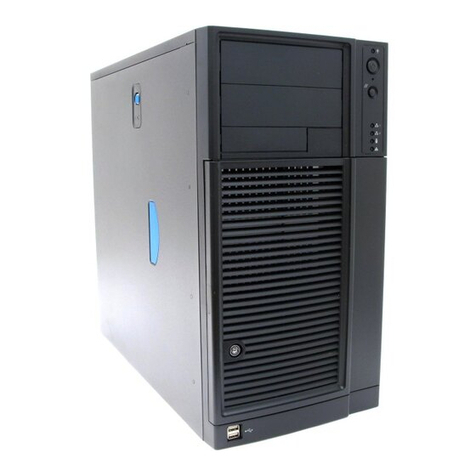
Intel GS-SR195V User guide

Intel

Intel GS-SR195V User guide

Intel M70KLP Series Configuration guide

Intel

Intel M70KLP Series Configuration guide

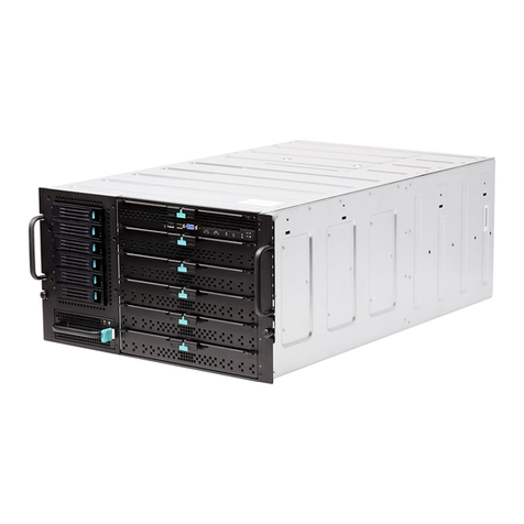
Intel S7000FC4UR - Server System - 0 MB RAM User manual
Intel

Intel S7000FC4UR - Server System - 0 MB RAM User manual

Popular Server manuals by other brands

Auerswald COMtrexx Advanced instructions

Auerswald

Auerswald COMtrexx Advanced instructions

NEC Express 456-01721-000 Read me first

NEC

NEC Express 456-01721-000 Read me first

HP Proliant DL580 user guide

HP

HP Proliant DL580 user guide

NEC Univerge SV8100 Configuration guide

NEC

NEC Univerge SV8100 Configuration guide

Dell EMC PowerEdge R550 6PX6M Installation and service manual

Dell

Dell EMC PowerEdge R550 6PX6M Installation and service manual

Sharkoon USB LANPORT 100 manual

Sharkoon

Sharkoon USB LANPORT 100 manual

Dell Wyse 5040 AIO quick start guide

Dell

Dell Wyse 5040 AIO quick start guide

LG Centric PCS200R Pro Installation & Setup, Quick Reference, Warranty

LG

LG Centric PCS200R Pro Installation & Setup, Quick Reference, Warranty

Polycom 3725-18101-001B Administrator's guide

Polycom

Polycom 3725-18101-001B Administrator's guide

HP ProLiant DL320 Generation 5 user guide

HP

HP ProLiant DL320 Generation 5 user guide

HP D7171A - NetServer - LPr user guide

HP

HP D7171A - NetServer - LPr user guide

Sun Microsystems Sun Fire T1000 Service manual

Sun Microsystems

Sun Microsystems Sun Fire T1000 Service manual

Lenovo ThinkServer TD230 Garantie et support

Lenovo

Lenovo ThinkServer TD230 Garantie et support

Fujitsu PRIMERGY TX300 S5 operating manual

Fujitsu

Fujitsu PRIMERGY TX300 S5 operating manual

Lenovo 70D6 User guide and hardware maintenance manual

Lenovo

Lenovo 70D6 User guide and hardware maintenance manual

Acer AR385 F1 Specifications

Acer

Acer AR385 F1 Specifications

RGB Networks Application Media Server Hardware setup guide

RGB Networks

RGB Networks Application Media Server Hardware setup guide

Lexmark 642e - X MFP B/W Laser troubleshooting guide

Lexmark

Lexmark 642e - X MFP B/W Laser troubleshooting guide

manuals.online logo
manuals.online logoBrands
  • About & Mission
  • Contact us
  • Privacy Policy
  • Terms and Conditions

Copyright 2025 Manuals.Online. All Rights Reserved.