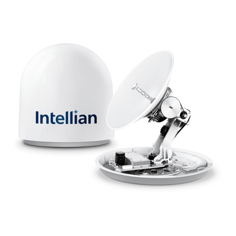
Intellian t80W User manual

Installation and Operation User Guide
Marine Satellite Communication Antenna System
t80W

Serial number of the product
This serial number will be required for the all troubleshooting or service inquiries.
© 2012 Intellian Technologies Inc. All rights reserved.
Intellian and the Intellian logo are trademarks of Intellian
Technologies, Inc., registered in the U.S. and other countries.
t80W, w-Series, and t-Series are trademarks of Intellian Technologies, Inc.
Intellian may have patents, patent applications, trademarks,
copyrights, or other intellectual property rights covering subject
matter in this document. Except as expressly provided in any
written license agreement from Intellian, the furnishing of this
document does not give you any license to these patents,
trademarks, copyrights, or other intellectual property.
All other logos, trademarks, and registered trademarks are
the property of their respective owners. Information in this
document is subject to change without notice.
Every effort has been made to ensure that the information
in this manual is accurate. Intellian is not responsible
for printing or clerical errors.
Doc. No. 2012U1-UM1031-V1_1
Americas
Intellian Technologies USA, Inc.
9004 Research Drive
Irvine, CA 92618, USA
Tel 949-727-4498
Toll Free 888-201-9223
Fax 949-271-4183
Email [email protected]
Europe
Intellian B.V.
Bristolstraat 1, 3047AB
Rotterdam, Netherlands
Tel +31-1-0820-8655
Fax +31-1-0820-8656
Email [email protected]
MEA & APAC
Intellian Technologies, Inc.
2F Dongik Bldg., 98 Nonhyun-dong,
Gangnam-gu, Seoul 135-010, Korea
Tel +82-2-511-2244
Fax +82-2-511-2235
Email [email protected]

INDEX

t80W – Marine Satellite TV Antenna System
4
INDEX
INTRODUCTION 5
Introduction to Intellian t80W 6
Features of Intellian t80W 7
INSTALLING THE ANTENNA 8
System Package 9
Planning the Installation 13
Antenna Installation 16
INSTALLING THE ACU 26
Mounting the ACU 27
Connecting the System Cables 29
Ship Gyrocompass Connection 31
OPERATING THE ACU 32
Introduction 33
Normal mode 34
Setup mode 38
Installation Settings 39
Antenna Settings 42
Satellite Settings 57
System Settings 66
OPERATION THE PC PROGRAM 72
Introduction 73
Program Initialing and Serial Port Setup 74
Main Menu 75
Controller Menus 78
Set Antenna GPS and Find Antenna Angle 78
Set Satellite Information 79
Set Tracking Information of Satellite [Primary] 80
Set Tracking Information of Satellite [Secondary] 82
Move Antenna and Skew Calibration 83
Antenna Information and Set Antenna Parameters for Control 84
Diagnosis & Set Antenna Parameters for Control 86
WARRANTY 88
Appendix: t80W Technical Specication 89

5
INTRODUCTION
Introduction to Intellian t80W
Features of Intellian t80W
INTRODUCTION

t80W – Marine Satellite TV Antenna System
6
Introduction to Intellian t80W
The Intellian t80W antenna locks onto satellites quickly and provides seamless
operation in all regions, offering global coverage. The antenna delivers this
performance by utilizing a fully stabilized 3-axis platform, as well as a fourth axis for
LNB auto-skew control. In addition, built-in as standard, the internal GPS combined
with Intellian's patented Wide Range Search (WRS®) provides the fastest satellite
acquisition possible. Multiple HD receivers can be connected to the system as
standard, providing a truly hands off global coverage depending on the regions
visited.
The Intellian t80W incorporates the patented WorldView™ LNB (Low Noise Block-
Down Converter), which automatically switches frequency depending on the region
the antenna is operating in; all of the switching information is contained in the
Antenna Control Unit (ACU). As the satellite TV provider is selected electronically,
there is no requirement to purchase multiple LNB modules, recongure complex
systems and manually change the LNB unit inside the antenna dome each time the
vessel crosses into a different satellite service region.
The t80W antenna has a broad elevation range, from -15° to +110°, enabling
operation in all conditions and the cross level axis ensures uninterrupted viewing
even when the antenna is operating near the equator. The t80W dome is designed
to complement the v80G VSAT antenna, providing customers with a compact dual
antenna solution for communications and entertainment.
All Intellian antenna systems are designed, manufactured and tested to withstand
the company's industry-leading standards for vibration and extreme shock in all sea
states and weather conditions.

7
INTRODUCTION
Features of Intellian t80W
Global Satellite Services Compatibility
Intellian t80W provides boaters with seamless and uninterrupted satellite TV service
across multiple coverage areas and service providers offering cost-effective solutions
and straightforward, simple operation from the Americas (circular polarized), as well
as Europe, the Middle East and the Asia Pacic region (linear polarized) with one
LNB module.
Hands-Free WorldViewTM LNB Module
The WorldViewTM LNB module is built with precise pioneering technology of ±25
kHz (±2.5ppm) stability and is designed to receive multi-band and multi-polarization
satellite TV services around the globe. Therefore, boaters are no longer required to
manually switch out the LNB inside the antenna dome or re-wire the system when
the vessel travels from region to region.
DVB-S2 Digital TV Receptions
Some of the HD TV services have moved onto DVB-S2 and will be more in the
future. Thanks to Intellian’s groundbreaking DVB-S2 digital TV technology, now
boaters are able to enjoy their favorite DTH entertainment at sea, just like home.
Wide Elevation Range
The wide elevation range from -15° to 110° enables the t80W to have seamless
signal reception while the vessel is traveling near the Equator or Polar Regions.
Global Satellite Library
The t80W includes the pre-programmed global satellite library which allows the
boaters to select the desired satellite while travelling from region to region. Once
the satellite is selected the WorldViewTM LNB module will automatically switch to the
corresponding local frequency to receive the signal.

t80W – Marine Satellite TV Antenna System
8
INSTALLING THE ANTENNA
System Package
Antenna Unit
ACU (Antenna Control Unit)
Installation Kit
Planning the Installation
Selection of Antenna Installation Site
System Cables
Power Requirement
Tools Required for Installation
Antenna Installation
Unpacking the t80W Package Box
Antenna Dimensions
Antenna Mounting Templates
Installing the System Cables
Mounting the Radome
RF Cable Connections
Position the Radome

9
INSTALLING THE ANTENNA
System Package
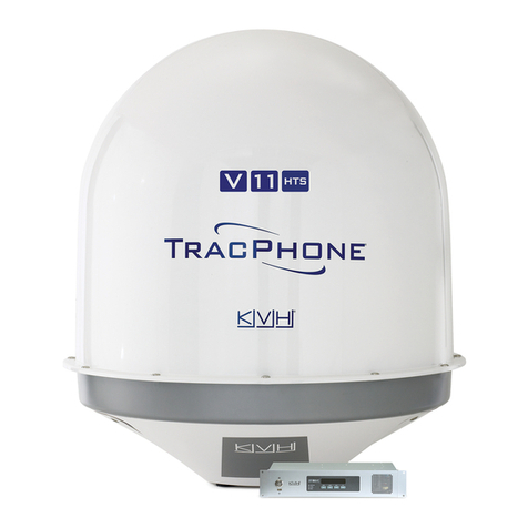
The Intellian t80W consist of two major units, an antenna unit and an antenna
control unit (ACU).
Antenna Unit
The antenna unit includes an antenna pedestal inside a radome assembly unit. The
pedestal consists of the satellite antenna main dish and sub-reector module with
a WorldViewTM LNB module mounted on a stabilized pedestal. The radome protects
the antenna pedestal assembly unit from the severe marine environment.
ACU (Antenna Control Unit)
Antenna Control Unit (ACU) provides the power to the antenna and controls the
various settings of the antenna. Additionally, VFD (Vacuum Fluorescent Display)
allows you to operate the ACU in the dark.
Front panel
Rear panel

t80W – Marine Satellite TV Antenna System
10
Installation Kit
Contains the items required for securing the antenna unit and ACU to the vessel.
Antenna Q’ty Description Size Remark
5Hex. Bolt M12 x 60L
Antenna-Deck
5Flat Washer M12
5Spring Washer M12
10 Hex. Nut M12
ACU Q’ty Description Size Remark
5Self-Tapping
Screw ø 4 x 16 Table Mount
Bracket
10 Flat Head Screw M3 x 8L Rack Mount
Bracket ACU
5Sems Bolt M3 x 12L Table Mount
Bracket ACU

11
INSTALLING THE ANTENNA
Image Q’ty Description Size Remark
1
2
ACU
Bracket
Rack - ACU-19inch Rack
2 Table - ACU-Table
2 1 RG6 Cable 30m ANT - ACU RF Cable
3 1 RG6 Cable 3m ACU - IRD Cable
4 1 AC Power Cable
(CEE 7/7) 1.5m ACU Power
5 1 PC Serial Cable 1.8m ACU to PC
6 1 USB Cable
(A-A/M-M) 1.8m ACU to PC
7 1 Synchro
Connector AK950-5 ACU (Synchro)
8 1 Step by Step
Connector AK950-4 ACU (Step-by-Step)
9 1 NMEA Out
Connector AK950-3 ACU (NMEA Out)
10 2
Gyro NMEA / GPS
NMEA In
Connector
AK950-2 ACU (Gyro NMEA / GPS
NMEA In Connector)
11 2 Rubber Gland RG6 RG6 Cable-Antenna
Other Components

t80W – Marine Satellite TV Antenna System
12
12 5 Hex Socket
Head Cap M6x40L Radome (Top-Bottom)
13 5 Dome Washer M6 Radome (Top-Bottom)
14 1 Installation CD - -
15 1 User Manual - -
16 1 Mounting
Template - -

13
INSTALLING THE ANTENNA
Planning the Installation
Selection of Antenna Installation Site
Install the antenna in accordance with the following procedures to insure maximum
performance of the antenna.
The antenna should be installed in a place where there is all round clear view of
the horizon. Please be sure there are no obstacles within 15 degrees above the
antenna. Any obstacles can prevent the antenna from tracking the satellite signal
(Refer to the drawing).
Do not install the antenna near by the radar especially on the same plane as their
energy levels may overload the antenna front-end circuits. It is recommended to
position the antenna at least 4 feet (1.2m) above or below the level of the radar and
minimum of 15 feet (4.6m) away from the high power short wave radars.
The mounting platform should be rigid enough and not subjected to excessive
vibration. The movement of the antenna can be minimized by installing at the center
of the vessel. For optimal performance of the antenna, it is not recommended to
install at any corner of the vessel, where the movement of the vessel is the greatest.
Install the bottom of the antenna parallel to the surface of the sea and x tightly to
the structure of the vessel.
When setting the antenna down, be careful not to damage the RF connector. Striking
the connectors on the bottom directly will damage the connector.
Elevation Limit
of Obstacles
Antenna Unit Obstacle
15°

t80W – Marine Satellite TV Antenna System
14
System Cables
Before installing the system cables, you need to take the following points into
consideration.
1. All cables need to be well clamped and protected from physical damage and
exposure to heat and humidity.
2. Cable with a tight bend radius is not allowed.
3. Where a cable passes through an exposed bulkhead or deck head, a watertight
gland or swan neck tube should be used.
RF Cable (Customer Furnished)
Due to the voltage losses across the length of the RF coax on L-Band, Intellian
recommends the following 75 ohm coax cable types for standard system
installations. For cables that run longer than 100 meters, please consult Intellian
Technologies.
Power Requirement
Intellian t80W has been designed to work on a vessel’s power supply rated at 110-220 V AC.
Gyro Compass / GPS Interface Cable (Customer Furnished)
Multi-conductor, Shielded
2 conductors for NMEA
Run Length Coax Type
Up to 35 meters RG6 or LMR-300-75
Up to 60 meters RG11 or LMR-400-75
Up to 100 meters LMR-600-75

15
INSTALLING THE ANTENNA
Tools required for Installation
13 mm Spanner
11 mm Spanner
Phillips Head
Screwdriver
Flat Head
Screwdriver (Min. 5mm)
19 mm Spanner5 mm Allen/Hex key

t80W – Marine Satellite TV Antenna System
16
Antenna Installation
Unpacking the t80W Package Box
Step 1.
Remove the top panel.
Step 2.
Remove ACU box and installation kit box.

17
INSTALLING THE ANTENNA
Step 3.
Remove the 4 shipping bolts that mount the antenna to the pallet.

t80W – Marine Satellite TV Antenna System
18
Step 4.
Open the top radome and remove the shipping restraints
(3 xing brackets mounted to the antenna pedestal and the azimuth axis).
M6 Dome Washer
M6 Hex Wrench Bolt

19
INSTALLING THE ANTENNA
Antenna Dimensions
The method of installation and mounting of antenna may vary with vessel design
but the following procedures are applicable in most situations, and will result in a
secure and effective installation. Conrm the height and diameter of the antenna
before installing it.
Radome Dimensions
113 cm (44.5")
114 cm (44.9")

t80W – Marine Satellite TV Antenna System
20
Antenna Mounting Templates
The mounting holes must be in the exact same place as shown in the diagram
below.
Bow direction
52 cm (20.5”)
Radome Bottom
30.4cm (12”)
30.4 cm (12")
24.75 cm (9.74")
24.75 cm (9.74")
Table of contents
Other Intellian Antenna manuals

Intellian
Intellian GX60 User manual

Intellian
Intellian i3 User manual

Intellian
Intellian v130 User manual

Intellian
Intellian FB250 User manual

Intellian
Intellian t110W User manual

Intellian
Intellian t110W User manual

Intellian
Intellian i2 User manual

Intellian
Intellian i3 User manual

Intellian
Intellian i3 User manual

Intellian
Intellian i9 User manual

Intellian
Intellian V110 User manual

Intellian
Intellian i9P User manual

Intellian
Intellian GX60 User manual

Intellian
Intellian v150NX User manual
Intellian
Intellian i6W User manual

Intellian
Intellian s6HD User manual

Intellian
Intellian GX100PM User manual

Intellian
Intellian V100 User manual

Intellian
Intellian i2 User manual

Intellian
Intellian v240M User manual