15
o
Coil Nailer
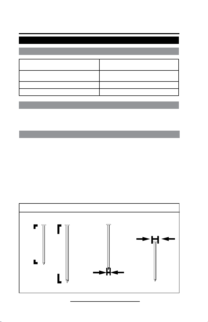
Drives Wire Collated Nails (1-3/4" to 2-3/4" / 45 to 70mm)
Model No. CN70-15
Item No. 65560
7
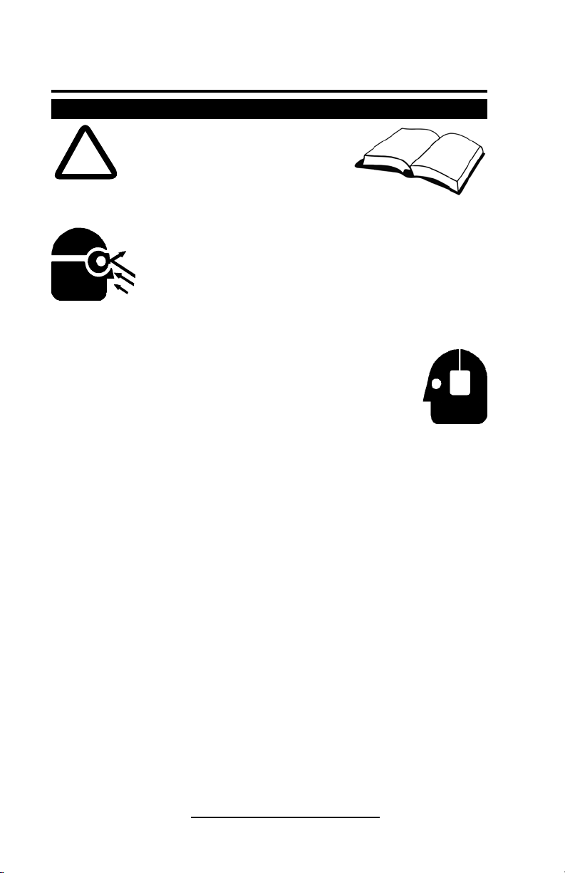
Interchange Brands Operator’s Manual
10. STAY ALERT.
Watch what you are doing. Use common sense and do not operate the nailer
when you are tired. The nailer should never be used if you are under the influence
of alcohol, drugs or medication that makes you drowsy.
11. KEEP WORK AREA CLEAN.
Cluttered areas invite injuries. Clear all work areas of unnecessary tools, debris,
etc.
12. DO NOT USE THE NAILER AS A HAMMER.
13. NEVER CARRY THE NAILER BY THE HOSE.
14. HANDLE THE NAILER CAREFULLY.
This nailer was designed for driving nails into wood and similar items. Operate the
nailer safely and correctly and do not use for purposes other than those specified
in this manual.
Because of high air pressure in the nailer, cracks in the surface are dangerous. To
avoid tool damage, do not drop the nailer or strike the nailer against hard surfaces,
and do not scratch or engrave on the nailer. Handle the nailer carefully.
15. BEFORE USING THE NAILER, CHECK TO MAKE SURE PARTS ARE NOT
BROKEN OR MISSING AND THAT ALL SCREWS ARE TIGHT. DO NOT
OPERATE A TOOL THAT IS OPERATING ABNORMALLY.
If the nailer appears to be operating unusually, making strange noises, has parts
missing or appears to be defective, stop using it immediately and arrange for
repairs by an authorized service center.
16. BEFORE STARTING WORK, CHECK TO SEE IF YOUR TOOL HAS A
FASTENING OPERATION SWITCHING DEVICE.
(Not available on all tool models.)
If this nailer includes a fastening operation switching device, check the setting of
the operation switching device before starting work. If the switching device is not
set properly, the nailer will not operate correctly.
17. CHECK SAFETY/PUSH LEVER BEFORE USE.
Make sure the safety/push lever operates properly. Never use the nailer unless the
safety/push lever is operating properly, otherwise the nailer could drive a fastener
unexpectedly. Do not tamper with or remove the safety/push lever, otherwise the
safety/push lever becomes inoperable.
18. CHOICE OF TRIGGER METHOD IS IMPORTANT.
Read and understand section titled “Methods of Operation.”
(Choice of trigger method is not available on all tool models.)
19. DO NOT USE OXYGEN, COMBUSTIBLE OR OTHER BOTTLED GASES.
EXPLOSION MAY OCCUR.
Never use oxygen, combustible gases or any other bottled gases as a power
source for the nailer. Use of these gases is dangerous, as the nailer will explode.
Use only clean, dry, regulated compressed air as a power source.
20. DO NOT EXCEED 100psi.
Do not exceed maximum recommended air pressure 100psi. Never connect the
nailer to pressure which potentially exceeds 150psi as the nailer can burst.
21. NEVER USE IN PRESENCE OF FLAMMABLE LIQUIDS OR COMBUSTIBLES.
The nailer produces sparks during operation. Never use the nailer on sites
containing lacquer, paint, benzine, thinner, gasoline, gases, adhesive agents or
other materials which are combustible or explosive.