Ottimo Diagrams
Joining Sections
3
1. Remove excess paint from the four radiator faces to be joined together
by scraping a at knife blade across the surface.
2. Place both halves to be assembled on a at even surface and align
the joining surfaces. The radiator sections and joining nipples have one
left and one right hand thread - the Nipples must be inserted correctly
to avoid cross threading. The end of the nipple with the right hand
thread has a smooth edge; the end with the left hand thread has a
serrated edge.
Carefully insert the barrel nipples into both waterways on one half, taking
care not to damage the threads, these can be screwed in a couple of turns
each. Apply a little joining compound to the soft bre gasket and position
this gasket within the central groove on the nipple.
3. Carefully insert the joining key through the collector until it locates the
barrel nipple and gradually close the halves by equal amounts until tight
(please see diagram).
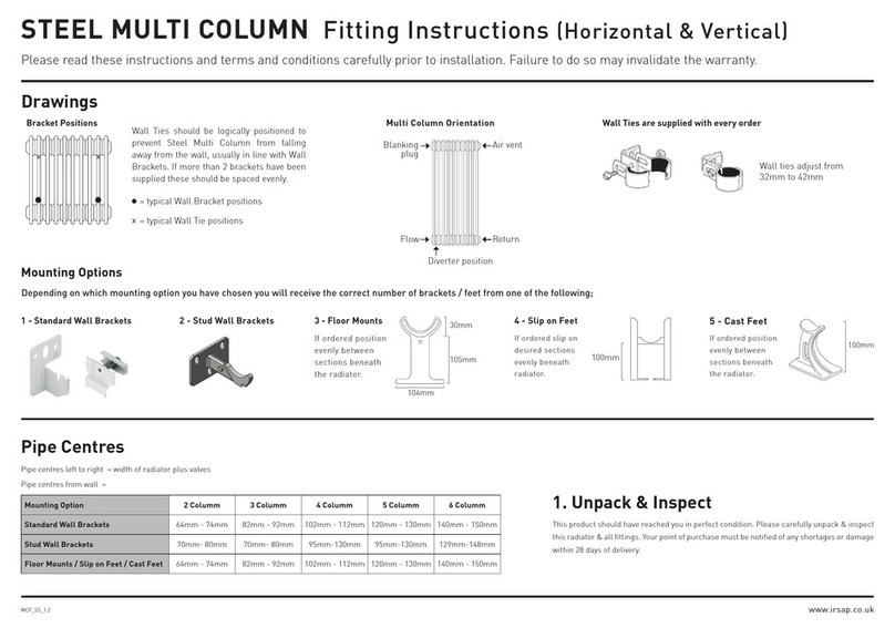
Pipe Centres
Pipe centres left to right : 80mm x no. sections + 20mm (bushes)
Pipe centres from wall : 67mm to 71mm
Depth from wall :
1480 & 1880 models: 130mm to 134mm
598 & 698 models: 127mm to 131mm
Unpack & Inspect
1
The Radiator Company prides itself on selecting products from manufacturers
who exercise tight quality control measures. We only select models with excellent
standards of welding and brazing, as well as high quality nishes. All of our
products are well packaged and should reach you in perfect condition. Just in case
however, we offer a 5 year no quibble guarantee for all aluminium radiators.
Please carefully unpack and inspect this radiator and all ttings.
The Radiator Company must be notied of any shortages or
damage within 28 days of delivery. For further information
please see terms and conditions on back page.
Joining Sections Together
1 2 3
Standard Conguration of Bushes
Contents
2
For the 1480 & 1880mm models, you are
supplied with a spring diverter, which is
installed in the lower waterway at either end.
This is installed by pushing the cap rmly
in the waterway until it locates against the
barrel nipple and is retained in place by the
bush. The ow must enter this end rst.
Fit Diverter (1480 /1880mm models only)
5
6Mark Brackets and hang radiator
7Commission
Diagram A
Diagram B
The bushes for the Ottimo are handed with either a left or right hand thread.
The bush marked with an “S” has a left hand thread and shoujld be tightened
anti-clockwise, and the bushes marked with a “D” has a right hand thread and
needs to be tightened Clockwise. Please see Diagram B.
IMPORTANT NOTE:
Bushes can be easily damaged if forced or incorrectly tted (this will inevitably
cause leaks). Bushes require a dry t connection only; you must not use any
Compound materials (e.g. Jet Blue) or Plumbers Hemp. If you choose you
may use up to 4 turns of PTFE tape to help seal the threads (the tape should be
applied in the direction of the thread and no more than this amount should be
used as this may cause leaks to occur)
Fit Bushes
4
Please Note: In accordance with Part L1 2006 of the Building Regulations
and BS7593:1992 code of practice for the treatment of hot water and central
heating systems, we strongly recommend flushing the heating system post
installation of new radiators and then adding the correct quantity and type of
inhibitor for use with your radiator and system to prevent corrosion. Damage
caused to systems not protected by a suitable inhibitor will not be covered by
manufacturer’s guarantee.
103
67 to 71
127 to 131
80
80mm x no.sec + 20mm
598 /
698
1 Fittings Pack including:
• 4 bushes with gaskets
• 1 Airvent
• 1 Blanking Plug (if required)
• 1 Airvent Key
• Spring Diverter (only for 1480 / 1880mm high models)
Wall Brackets (in parts):
4 (up to 20 sections)
6 (21 - 30 section)
8 (30+ sections)
2
3
4
3. Slide the bracket down the centre of the back plate which should
be xed to the wall.
4. Attach the top cover plate to the top of the bracket.
5. Lift the radiator and slide through onto the bracket hook. The hooks will sit
underneath the collectors.
1. For even weight distribution we suggest the brackets are
placed one section in from each side. Hold up the back plates in
position on the wall and mark through the screw holes. Ensure
these are horizontally level using a spirit level, then check the
positions against your radiator. If correct, using suitable drill bits
and plugs, secure the back plates to the wall.
2. Insert the supplied screw into the hook, and
screw in to the desired position. (This screw will
control the height of which the hook sits on the
bracket.)
1
Tighten ‘S’
Anti-clockwise
Tighten ‘D’
Clockwise
106
67 to 71
130 to 134
1480 /
1880
598 / 698mm
models
1480 / 1880mm
models
all models
80 80
