manuals.online logo
Brands
  1. Home
  2. •
  3. Brands
  4. •
  5. IRSAP
  6. •
  7. Heater
  8. •
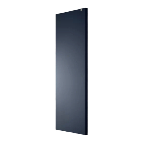
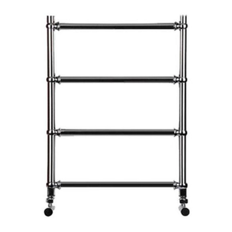
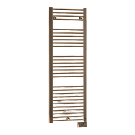
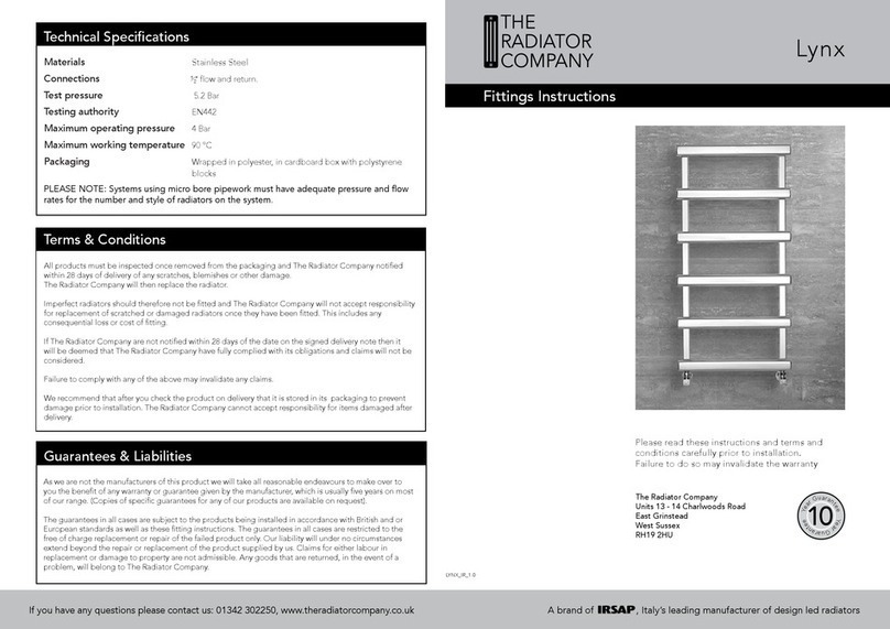
  9. IRSAP The Radiator Company Lupin Electric User manual

IRSAP The Radiator Company Lupin Electric User manual

Materials Steel.
Packaging Polythene wrap and boxed
Voltage-feed 230V 50Hz, 1ph
Insulation Class II
Protection degree IP44
Length electrical cable 1200mm
Electronic ambient thermostat with “pilot wire” control
The association between electrical heater and the radiator model allows a radiator surface
temperature no higher than about 70°C. The Towel Warmer is lled in the factory with a measured
quantity of a special liquid, to optimize the heat transmission. Because of this, any repairs which
require the opening of the towel-rail, must be executed from the manufacturer. This applies equally
in the unlikely event of the special liquid leaking out of the towel-rail.
All products must be inspected once removed from the packaging and The Radiator Company notied
within 28 days of delivery of any scratches, blemishes or other damage. The Radiator Company will then
replace the radiator.
Imperfect radiators should therefore not be tted and The Radiator Company will not accept responsibility for
replacement of scratched or damaged radiators once they have been tted. This includes any consequential loss
or cost of tting.
If The Radiator Company are not notied within 28 days of the date on the signed delivery note then it will be
deemed that The Radiator Company have fully complied with its obligations and claims will not be considered.
Failure to comply with any of the above may invalidate any claims.
We recommend that after you check the product on delivery that it is stored in its packaging to prevent damage
prior to installation. The Radiator Company cannot accept responsibility for items damaged after delivery.
Terms & Conditions
Guarantees & Liabilities
The Lupin towel rail is guaranteed for 10 years, the electric parts for 2 years. The guarantees in
all cases are subject to the products being installed in accordance with British and or European
standards as well as these fitting instructions. The guarantees in all cases are restricted to the free
of charge replacement or repair of the failed product only. Our liability will under no circumstances
extend beyond the repair or replacement of the product supplied by us. Claims for either labour in
replacement or damage to property are not admissible. Any goods that are returned, in the event
of a problem, will belong to The Radiator Company.
Technical Specications
Please read these instructions and terms and
conditions carefully prior to installation.
Failure to do so may invalidate the warranty.
Lupin Electric
Fittings Instructions
LUP_ELE_1.0
THE
RADIATOR
COMPANY
The Radiator Company
Units 13 - 14 Charlwoods Road
East Grinstead
West Sussex
RH19 2HU
Cod. 1180M1019
Maintenance - Recommendations for use
• This radiator should be cleaned regularly, particularly when in use (at least once a month).
Switch off at the socket before cleaning the radiator. Clean it using a non-abrasive product
and a soft cloth.
• If you wish to open the window, it is advisable to switch the radiator to standby to save wasting energy.
• If you encounter any problems or the radiator needs to be repaired, do not do this yourself;
Please contact The Radiator Company.
If you have any questions please contact us: 01342 302250, www.theradiatorcompany.co.uk A brand of , Italy’s leading manufacturer of design led radiators
Bracket Postioning for Lupin
Electrical Connection
3
This radiator is designed for connection to a ~230 V power supply with a
xed socket. It comes with a connecting cable (A O5 VVF)
The cable must be connected to a junction box behind the radiator in
compliance with the applicable standards.
It is necessary to install an omnipolar cut-out, with a contact distance of
at least 3mm.
If the power cable gets damaged or needs to be changed, as a safety
precaution it must be replaced by the manufacturer, an authorised
after-sales service or a qualied Part P competent person.
You should have:
• 1 Towel Rail
• 4 Wall brackets (in parts)
Contents
2
You will need:
• Tape measure
• Electric drill and bits
• Spirit level
• Screwdrivers
• Allen Key
L H* W
mm mm mm
400 718 492
500 1210 984
600 1497 1271
- 1886 1640
= bracket positions
:
+
+
+
·
·/
/¶
+

A brand of , Italy’s leading manufacturer of design led radiators.
Radiators Position
The positioning of the Lupin Electric must be chosen very carefully.
It must be installed correctly and in compliance with building and
electric regulations.
This towel rail is a registered
Class II, IP 44 heating panel,
which is protected against water
spray. It can be installed in zone 2,
provided that the controls are in
zone 3 and cannot be reached by
anyone using the bath or shower.
• It must not be installed in zone 1.
• Never earth it.
• An electrical plug must not be used.
• Do not install below a power socket. It must only be used indoors.
H* without electrical part
Operation and Settting Operation and Settting
Radiator with electronic
thermostat featuring “pilot-
wire” control.
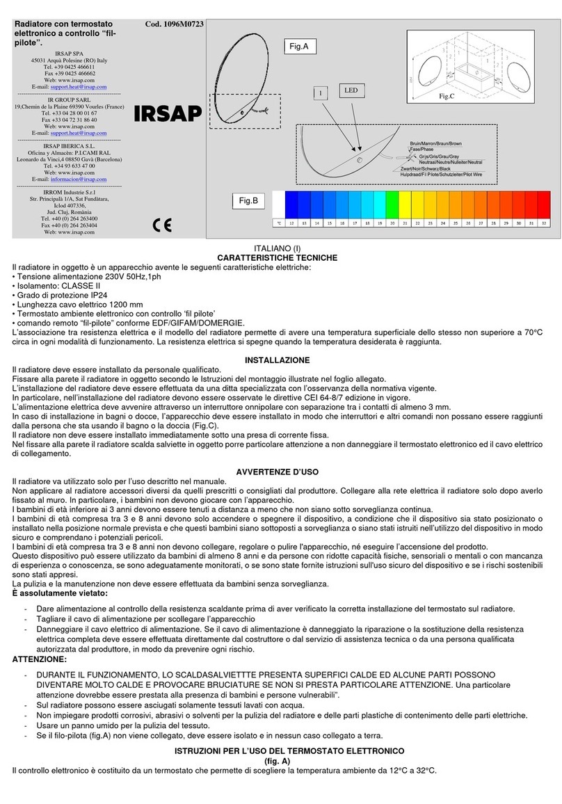
Cod. 986M1018
ENGLISH (UK)
TECHNICAL FEATURES
The Towel Warmer radiator is an electrical appliance endowed with the following features:
• Voltage-feed 230V 50Hz, 1ph
• Insulation Class II
• Protection degree IP44
• Length electrical cable 1200 mm
• Electronic ambient thermostat with "pilot wire" control in compliance with EDF/GIFAM/DOMERGIE
The association between electrical heater and the radiator model allows a radiator surface temperature no higher than about 70°C
The Towel Warmer radiator is filled in the factory with a measured quantity of a special liquid, to optimize the heat transmission.
Because of this, any repairs which require the opening of the towel-rail, must be executed from the manufacturer.
This applies equally in the unlikely event of the special liquid leaking out of the towel-rail.
HEATING ELEMENT TECHNICAL CHARACTERISTICS
The thermostat can work exclusively when paired with a specially prepared electric heating element, equipped with safety devices to limit excess
temperature and make the system safe in the event of abnormal factors (see Warnings).
INSTALLATION
The radiator must be installed by qualified staff.
Always fix the heated Towel Warmer to the wall as per the assembly instructions enclosed.
The installation must be carried out by a specialized firm in compliance with the standards in force.
When installing the towel rail the IEC 60364-7-701 according to the edition in force must be complied.
To supply the tower rail radiator, an omnipolar switch, with at least 3 mm of distance between contacts, must be employed.
When installing in bathrooms or in shower-rooms, the appliance should be installed in such a way to avoid the switch and other controls to be reached
by people using the bathroom or the shower. (see Fig. B)
The radiator must not be installed immediately beneath a fixed current outlet.
Take utmost care while installing the Towel Warmer radiator to avoid damaging the electronic thermostat and the connecting cable.
In order to avoid every risk to the smallest children, we recommend installing the device in such way that the lowest heating pipe is at least 600 mm
above the ground.
DIRECTIONS FOR USE
The towel warmer must be used only for the purpose described in the manual. In particular, children must not play with the appliance.
Do not apply on the towel warmer radiator accessories other than those prescribed or recommended by the manufacturer.
Connect the towel warmer to the mains power supply only after it has been fixed to the wall.
Children under 3 must be kept at a distance unless under continuous surveillance.
Children between 3 and 14 years of age and persons with reduced physical, sensory or mental capacities, or who lack experience or the necessary
knowledge can use the towel warmer on condition that it has been positioned or installed in the normal position contemplated and they have been
instructed and trained in its safe use and are aware of the potential risks.
Children under the age of 14 must not connect the power plug, nor adjust or clean the appliance.
Children and persons with reduced physical, sensory or mental capacities, or who lack experience or the necessary knowledge must not perform
cleaning or routine maintenance of the towel warmer towel warmer.
It is absolutely prohibited:
 To power the heating element control before having checked the correct installation of the thermostat on the towel warmer towel warmer.
 To cut the power supply cable to disconnect the appliance
 To damage the power supply cable. If the power cable is damaged the complete electric heating element must be repaired or replaced by the
manufacturer or by their technical assistance service, or by a qualified person authorised by the manufacturer, so as to prevent any risk.
WARNING:
DURING OPERATION, THE TOWEL WARMER PRESENTS HOT SURFACES, SOME PARTS CAN GET VERY HOT, AND CAUSE
BURNS UNLESS PARTICULAR CARE IS TAKEN. Particular attention should be paid to the presence of children and vulnerable people
 During operation it is normal for the last two pipes at the bottom and the first one at the top to remain lukewarm.
 Only fabrics washed with water can be dried on the towel warmer.
 Do not use corrosive or abrasive products or solvents to clean towel warmer or the plastic parts that contain the electrical parts.
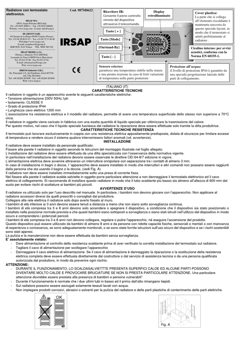
Key [ + ]
Rear-lit display
IR Receiver:



Key [Mode]
Plastic cover:
The part that connects to
the heating element is
kept hidden by this
special layout, so that the
thermostat adapts
perfectly to the radiator .
[On/stand-By] Internal buzzer: for
audible warnings, complies
with Standard EN 60335-1.
Key [ - ]
External sensor:
guarantees a stable temperature in the room
and a prompt reaction in the event of strong
temperature variations at the rear
Protection against water:
the protection level IP44 is guaranteed by
a special side projection of the
connecting parts.
IRSAP SPA
45031 Arquà Polesine (RO) Italy
Tel. +39 0425 466611 - Fax +39 0425 466662
Website: http://www.irsap.com
E-mail: info@irsap.it
----------------------------------------------------------
IR GROUP SARL
19,Chemin de la Plaine 69390 Vourles (France)
Tel. +33 04 28 00 01 67 - Fax +33 04 72 31 86 40
Web: http://www.irsap.com;
E-mail: irsaprhoss@irgroup.fr
----------------------------------------------------------
IRSAP-RHOSS Clima Integral, S.L.
Oficina y Almacèn: P.I.CAMI RAL
Leonardo da Vinci,4 08850 Gavà (Barcelona)
Tel. 93 633 47 00 - Fax 93 633 47 04
E-mail: www.informacion@irsap.com
www.irsap.com
----------------------------------------------------------
IRROM Industrie S.R.L.
Str. Pricipalà 1/A, Sat Fundàtara, Iclod 407336,
jud. Cluj, Romània
Tel: +40 (0)264 263400 - Fax: +40 (0)264 263404
Web: www.irsap.ro
Fig. A
Fig. B

1. ON/Stand-by
Press the [ON/Stand-by] key (Fig.1) to switch on the appliance or to activate "Stand-by" mode.
When it is active, the bottom area of the display shows the current time, while the top shows the set mode and the temperature. During “Stand-by”,
the display shows the letters “Stb”, the current time and the day of the week.
NOTE: When the device enters "Stand-by" mode, 2 bips are produced lasting 0.5 seconds. When the thermostat is on, it emits 1 bip per second.

Example of "Comfort" mode Example of "Stand-by" mode
 

2. OPERATING MODES SETTABLE FROM THE THERMOSTAT
Press the [Mode] key (fig.1) to select the desired mode.
An icon on the display will indicate the active operating mode (see table below).
Table of operating modes
2h
C
h
rono
Pilot
-
wire
Comfort
Night
Antifreeze
Holiday
2h Timer

Sequence of modes:
Chrono -> Holiday -> Pilot-wire -> Comfort -> Night -> Antifreeze -> 2h Timer
2.1 Chrono Mode
This operating mode allows the user to configure different temperature values for each hour of each day of the week. The “Comfort”/”Night”
temperatures and the related time intervals can thus be programmed.
To activate this function press the [Mode] key until the “Chrono” icon is displayed.
To select pre-set programming of the week P1, P2 or P3, hold down the [Mode] key for 3 sec.
Pre-set programs:
P1 = from day 1 to day 5 “Comfort” mode from 8 a.m. to 6 p.m. and “Night” mode in the other periods;
P2 = from day 1 to day 5 “Comfort” mode from 6 to 9 a.m. and from 5 to 11 p.m.; from day 6 to day 7 “Comfort” mode from 7 a.m. to 11 p.m.
and “Night” mode in the other periods;
P3 = totally configured by the customer.

2.2 Holiday Mode
“Holiday” mode activates the heating element of the electronic control when the ambient temperature falls below the antifreeze temperature.
It is recommended to use this mode when the room is not occupied for several days.
Press the [Mode] key until the respective icon is selected and set the holiday hours.
When this time is past, the thermostat returns to “Comfort” mode.
2.3 Pilot-wire Mode
In “Pilot-wire” mode, the appliance is run by a special control unit that sets the operating mode for all the connected thermostats.
The appliance also recognises the most advanced “Pilot-wire” system with six orders, which allows the use of the functions described below:
1. Stand-by: switches off the heating element but the thermostat remains on;
2. Comfort: maintains the “Comfort” temperature set by the user;
3. ECO: maintains the room temperature 3.5°C lower than the “Comfort” temperature;
4. Antifreeze: maintains the room temperature at 7°C;
5. Comfort-1: maintains the room temperature 1°C lower than the “Comfort” temperature;
6. Comfort-2: maintains the room temperature 2°C lower than the “Comfort” temperature.
To activate the “Pilot-wire” function:
 Press the [Mode] key until the “Pilot-wire” icon appears on the display.
 Set the desired temperature with the [+/-] keys and wait for the temperature to stop blinking on the display.
NOTE: if the “Pilot-wire” is not installed in the system, the predefined operating mode is “Comfort”. In this case, do not connect the “Pilot-
wire” cable of the thermostat to the yellow/green earth cable and insulated it.
Clock
Operating mode
icons
- Chrono
- Pilot-wire
- Comfort
- Night
- Antifreeze
- Holiday Lock keys icon
Temperatur
a
Detect open window
Chrono Program
selezionato
Day of the week
Comfort/Night Bar (Chrono mode)
Temperatur
a
impostata
IR receiver indicator
Temperatur
a
Set temperature
Temperatur
a
Active heating element indicator
Rear-lit display
Radiator with electronic
thermostat featuring “pilot-
wire” control.
Cod. 986M1018
ENGLISH (UK)
TECHNICAL FEATURES
The Towel Warmer is an electrical appliance with the following features:
• Voltage-feed 230V 50Hz, 1ph
•Insulation Class II
• Protection degree IP44
• Length electrical cable 1200 mm
• Electronic ambient thermostat with "pilot wire" control in compliance with EDF/GIFAM/DOMERGIE
The association between electrical heater and the radiator model allows a radiator surface temperature no higher than about 70°C
The Towel Warmer radiator is filled in the factory with a measured quantity of a special liquid, to optimize the heat transmission.
Because of this, any repairs which require the opening of the towel-rail, must be executed from the manufacturer.
This applies equally in the unlikely event of the special liquid leaking out of the towel-rail.
INSTALLATION
The radiator must be installed by qualified staff.
Always fix the heated Towel Warmer to the wall as per the assembly instructions enclosed.
The installation must be carried out by a specialized firm in compliance with the standards in force.
When installing the towel rail the IEC 60364-7-701 according to the edition in force must be complied.
To supply the tower rail, an omnipolar switch, with at least 3 mm of distance between contacts, must be employed.
When installing in bathrooms or in shower-rooms, the appliance should be installed in such a way to avoid the switch and other controls to be
reached by people using the bathroom or the shower. (see Fig. B)
The radiator must not be installed immediately beneath a fixed current outlet.
Take utmost care while installing the Towel Warmer to avoid damaging the electronic thermostat and the connecting cable.
In order to avoid every risk to the children, we recommend installing the device in such way that the lowest heating pipe is at least 600 mm above
the ground.
DIRECTIONS FOR USE
The towel warmer must be used only for the purpose described in the manual. In particular, children must not play with the appliance.
Do not apply on the towel warmer radiator accessories other than those prescribed or recommended by the manufacturer.
Connect the towel warmer to the mains power supply only after it has been fixed to the wall.
Children under 3 must be kept at a distance unless under continuous surveillance.
Children between 3 and 14 years of age and persons with reduced physical, sensory or mental capacities, or who lack experience or the necessary
knowledge can use the towel warmer on condition that it has been positioned or installed in the normal position contemplated and they have been
instructed and trained in its safe use and are aware of the potential risks.
Children under the age of 14 must not adjust or clean the appliance.
Children and persons with reduced physical, sensory or mental capacities, or who lack experience or the necessary knowledge must not perform
cleaning or routine maintenance of the towel warmer.
It is absolutely prohibited:
 To power the heating element control before having checked the correct installation of the thermostat on the towel warmer towel warmer.
 To cut the power supply cable to disconnect the appliance
 To damage the power supply cable. If the power cable is damaged the complete electric heating element must be repaired or replaced by the
manufacturer or by their technical assistance service, or by a qualified person authorised by the manufacturer, so as to prevent any risk.
WARNING:
DURING OPERATION, THE TOWEL WARMER PRESENTS HOT SURFACES, SOME PARTS CAN GET VERY HOT, AND CAUSE
BURNS UNLESS PARTICULAR CARE IS TAKEN. Particular attention should be paid to the presence of children and vulnerable people
 During operation it is normal for the last two pipes at the bottom and the first one at the top to remain lukewarm.
 Only fabrics washed with water can be dried on the towel warmer.
 Do not use corrosive or abrasive products or solvents to clean towel warmer or the plastic parts that contain the electrical parts.
Key [ + ]
Rear-lit display
IR Receiver:



Key [Mode]
Plastic cover:
The part that connects to
the heating element is
kept hidden by this
special layout, so that the
thermostat adapts
perfectly to the radiator .
[On/stand-By] Internal buzzer: for
audible warnings, complies
with Standard EN 60335-1.
Key [ - ]
External sensor:
guarantees a stable temperature in the room
and a prompt reaction in the event of strong
temperature variations at the rear
Protection against water:
the protection level IP44 is guaranteed by
a special side projection of the
connecting parts.
IRSAP SPA
45031 Arquà Polesine (RO) Italy
Tel. +39 0425 466611 - Fax +39 0425 466662
Website: http://www.irsap.com
E-mail: info@irsap.it
----------------------------------------------------------
IR GROUP SARL
19,Chemin de la Plaine 69390 Vourles (France)
Tel. +33 04 28 00 01 67 - Fax +33 04 72 31 86 40
Web: http://www.irsap.com;
E-mail: irsaprhoss@irgroup.fr
----------------------------------------------------------
IRSAP-RHOSS Clima Integral, S.L.
Oficina y Almacèn: P.I.CAMI RAL
Leonardo da Vinci,4 08850 Gavà (Barcelona)
Tel. 93 633 47 00 - Fax 93 633 47 04
E-mail: www.informacion@irsap.com
www.irsap.com
----------------------------------------------------------
IRROM Industrie S.R.L.
Str. Pricipalà 1/A, Sat Fundàtara, Iclod 407336,
jud. Cluj, Romània
Tel: +40 (0)264 263400 - Fax: +40 (0)264 263404
Web: www.irsap.ro
Fig. A
Fig. B
Operation and Settting
2.4 Comfort Mode
The “Comfort” temperature corresponds to the temperature desired by the user and it is the temperature used for “Chrono”, “Pilot-wire” and
“Comfort” modes.
This operating mode is intended for normal use of the appliance.
 Press the [Mode] key until the “Comfort” icon appears on the display;
 Set the desired temperature with the [+/-] keys and wait for the temperature to stop blinking on the display.
The “Comfort” temperature can be set in the whole interval ("Night" mode temperature + 0.5°C) to 32°C.
2.5 Night Mode
In “Night” mode the settable temperature is lower than the “Comfort” temperature. It is recommended to use this mode during the night or when
the room is not used for 2 hours or more.
The “Night” temperature is also used for “Chrono” mode.
 Press the [Mode] key until the “Night” icon appears on the display;
 To modify the “Night” temperature, use the [+/-] keys and wait for the temperature to stop blinking on the display.
NOTE: The “Night” temperature must always be lower than or the same as the “Comfort” temperature; for this reason the “Night”
temperature can be set between 7°C and the “Comfort” temperature minus 0.5°C.
2.6 Antifreeze Mode
In “Antifreeze” mode the temperature is fixed at 7°C. The appliance activates the heating element automatically when the room temperature falls
below 7°C.
It is recommended to use this mode when the room is not used for several days.
 Press the [Mode] key until the “Antifreeze” icon appears on the display.
2.7 2h Timer Mode
“2h Timer” mode can be used to heat the room rapidly or to dry towels faster.
 Press the [Mode] key until the “2h Timer” icon appears on the display.
The heating element is activated for 2 hours, irrespective of the set temperature (in any case, the maximum temperature that can be reached in
the room will be 32°C). At the end of the 2 hours, the thermostat returns to the mode set previously. If necessary, the user can deactivate the
function at any time by pressing the [Mode] key.

NOTE: Do not activate the 2h Timer mode directly from the Stand-by status
3 FUNCTIONS
3.1 Keyboard lock
It is possible to lock the keys of the device to avoid accidental modifications of the settings.
Hold down the [+] and [-] keys for 3 seconds to lock all the keys except the [On/Stand-by] key.
The key-lock icon will appear on the display.
To unlock the keys, hold down the [+] and [-] keys again for 3 seconds. The key-lock icon will disappear from the display.
3.2 “Detect open window” function
The “Detect open window” function allows an open window to be detected by perceiving a sudden decrease of the temperature in the room.
In this case, the device deactivates the heating element for a maximum of 30 minutes or until an increase in the ambient temperature indicates
that the window has been closed.
When this function is enabled, the icon is lit.
When the device detects that the window might be open, the “Open window” icon starts to blink.
When the function is deactivated, the “Open window” icon is not shown on the display.
3.3 Adaptive Starting Control (ASC)
If activated, this function switches on the radiator earlier than the “Chrono” program (maximum 2 hours earlier) to ensure that the room has
reached the desired temperature at the set time.
Note: the function needs at least a couple of days to reach maximum efficiency.
4 SETTINGS
Setting of the device.
From “Stand-by” mode, hold down the [Mode] key for at least 3 seconds.
The message "SEt" will be shown at the bottom of the display:
To select what you want to change:
Press the [+] key to choose between tEd (date and time), Pro9 (weekly program P3) and Funct (functions).
4.1 tEd (date and time):
Press the [Mode] key to enter editing mode.
The flashing number indicates the day of the week currently selected: press the [+]/[-] keys to set the desired day.
Press the [Mode] key again to confirm the selected day.
After that, the procedure for entering the time begins and the current time flashes on the display. “Hours”: use the [+] and [-] keys to set the
correct hour and confirm the selected value by pressing the [Mode] key.
“Minutes”: same procedure as for the hours. Confirm the selected value by pressing the [Mode] key.
At the end of the procedure, a double beep confirms the data acquired and the thermostat returns to “Stand-by” mode.
If you have any questions please contact us: 01342 302250, www.theradiatorcompany.co.uk A brand of , Italy’s leading manufacturer of design led radiators
Operation and Settting
2.4 Comfort Mode
The “Comfort” temperature corresponds to the temperature desired by the user and it is the temperature used for “Chrono”, “Pilot-wire” and
“Comfort” modes.
This operating mode is intended for normal use of the appliance.
 Press the [Mode] key until the “Comfort” icon appears on the display;
 Set the desired temperature with the [+/-] keys and wait for the temperature to stop blinking on the display.
The “Comfort” temperature can be set in the whole interval ("Night" mode temperature + 0.5°C) to 32°C.
2.5 Night Mode
In “Night” mode the settable temperature is lower than the “Comfort” temperature. It is recommended to use this mode during the night or when
the room is not used for 2 hours or more.
The “Night” temperature is also used for “Chrono” mode.
 Press the [Mode] key until the “Night” icon appears on the display;
 To modify the “Night” temperature, use the [+/-] keys and wait for the temperature to stop blinking on the display.
NOTE: The “Night” temperature must always be lower than or the same as the “Comfort” temperature; for this reason the “Night”
temperature can be set between 7°C and the “Comfort” temperature minus 0.5°C.
2.6 Antifreeze Mode
In “Antifreeze” mode the temperature is fixed at 7°C. The appliance activates the heating element automatically when the room temperature falls
below 7°C.
It is recommended to use this mode when the room is not used for several days.
 Press the [Mode] key until the “Antifreeze” icon appears on the display.
2.7 2h Timer Mode
“2h Timer” mode can be used to heat the room rapidly or to dry towels faster.
 Press the [Mode] key until the “2h Timer” icon appears on the display.
The heating element is activated for 2 hours, irrespective of the set temperature (in any case, the maximum temperature that can be reached in
the room will be 32°C). At the end of the 2 hours, the thermostat returns to the mode set previously. If necessary, the user can deactivate the
function at any time by pressing the [Mode] key.

NOTE: Do not activate the 2h Timer mode directly from the Stand-by status
3 FUNCTIONS
3.1 Keyboard lock
It is possible to lock the keys of the device to avoid accidental modifications of the settings.
Hold down the [+] and [-] keys for 3 seconds to lock all the keys except the [On/Stand-by] key.
The key-lock icon will appear on the display.
To unlock the keys, hold down the [+] and [-] keys again for 3 seconds. The key-lock icon will disappear from the display.
3.2 “Detect open window” function
The “Detect open window” function allows an open window to be detected by perceiving a sudden decrease of the temperature in the room.
In this case, the device deactivates the heating element for a maximum of 30 minutes or until an increase in the ambient temperature indicates
that the window has been closed.
When this function is enabled, the icon is lit.
When the device detects that the window might be open, the “Open window” icon starts to blink.
When the function is deactivated, the “Open window” icon is not shown on the display.
3.3 Adaptive Starting Control (ASC)
If activated, this function switches on the radiator earlier than the “Chrono” program (maximum 2 hours earlier) to ensure that the room has
reached the desired temperature at the set time.
Note: the function needs at least a couple of days to reach maximum efficiency.
4 SETTINGS
Setting of the device.
From “Stand-by” mode, hold down the [Mode] key for at least 3 seconds.
The message "SEt" will be shown at the bottom of the display:
To select what you want to change:
Press the [+] key to choose between tEd (date and time), Pro9 (weekly program P3) and Funct (functions).
4.1 tEd (date and time):
Press the [Mode] key to enter editing mode.
The flashing number indicates the day of the week currently selected: press the [+]/[-] keys to set the desired day.
Press the [Mode] key again to confirm the selected day.
After that, the procedure for entering the time begins and the current time flashes on the display. “Hours”: use the [+] and [-] keys to set the
correct hour and confirm the selected value by pressing the [Mode] key.
“Minutes”: same procedure as for the hours. Confirm the selected value by pressing the [Mode] key.
At the end of the procedure, a double beep confirms the data acquired and the thermostat returns to “Stand-by” mode.
4.2 Pro9 (weekly program P3):
Press the [Mode] key to enter P3 editing mode:
Programming begins at 00:00 on the first day of the week.
The upper side display shows the setting time 00 in the example, meaning from 00:00 to 01:00.
Press the [+] key if you want the “Comfort” temperature for this time or press the [-] key if you want the "Night" temperature, then automatically
show 01 which means from 01:00 to 02:00, choose the temperature as before. The empty bar means "Night" temperature, the full bar means
“Comfort” temperature.
After having set all 24 hours, press the [Mode] key to change to day no. 2 of the week and proceed with the same procedure as the previous
day to set all the other days of the week (7).
At the end of the procedure, a double beep confirms the data acquired and the thermostat returns to “Stand-by” mode.
4.3 Funct (functions):
To activate or deactivate “Detect open window” and ASC (Adaptive Starting Control).
Press the [Mode] button to enter editing, the detect open window icon will flash: press the [+] key if you want to activate (On) or press the [-]
key if you want to deactivate (Off);
Press the [Mode] button to enter editing, now the ASC icon will flash: press the [+] key if you want to activate (On) or press the [-] key if you
want to deactivate (Off);
Press the [Mode] button to confirm; at the end of the procedure, a double beep confirms the data acquired and the thermostat returns to “Stand-
by” mode.
Note 1: the device might not succeed in detecting an open window if, for example, the thermostat is in an isolated area of the room, far from draughts,
close to an external source of heat or if the temperature variation in the room is too slow.
Note 2: when the symbol is lit, the heating element is active.
Note 3: the icon indicates that the signal from the remote control is received.
Note 4: in the event of loss of power, the “Chrono” mode settings (current day of the week, current time, daily program for the week) remain in the
memory for at least 5 minutes.
Note 5:
Attention: in the case "Timer 2h" mode is activated directly starting from stand-by status ("S t b" word on display) and, finished the two hours,
electronics is blocked, execute the following procedure:
1. keep [Mode] button pressed for at least 1 second;
2. release [Mode] button and immediately press the [ON / Stand-by] button.
Point 2 must be done very quickly so we recommend making more than one attempt.
REMOTE CONTROL (OPTIONAL)
The electronic thermostat is equipped with an IR receiver and can therefore be controlled at a distance using an optional remote control.
All the modes and the functions described above are available on the remote control.
INFORMATION FOR USERS
in accordance with article 14 of the Directive 2012/19/EU of 07/07/2012 on waste electrical and electronic equipment.
•The symbol shown above, present also on the equipment, indicates that it has been placed on the market and that, when the user decides to get
rid of it, it must be disposed of in separate waste collection (including all the components, sub-assemblies and consumer materials which are an
integral part of the product).
•For information on the systems for collecting these appliances, please contact the company or another subject enrolled in the various National
Registers for other countries in the European Union. Waste produced in the home (or of similar origin) may be consigned to systems for the separate
collection of urban waste.
•When buying a new appliance of an equivalent type, it is possible to hand over the old equipment to the seller. The seller will then contact the
subject in charge of the collection of the equipment.
•The appropriate separate collection of the scrapped equipment and the subsequent operations of processing, recovery and environment-
compatible disposal, allows the avoidance of potential negative effects on the environment and on human health, while favouring the recycling and
recovery of the component materials.
The unauthorised disposal of the product by the user entails the application of the sanctions contemplated under the national approval of Directives
2011/65/EU, 2008/98/EC and 2015/1127/EU.

Other IRSAP Heater manuals

IRSAP 1234M0620 User manual

IRSAP

IRSAP 1234M0620 User manual

IRSAP Radiator Company Kura User manual

IRSAP

IRSAP Radiator Company Kura User manual

IRSAP THE RADIATOR COMPANY LYNX User manual

IRSAP

IRSAP THE RADIATOR COMPANY LYNX User manual

IRSAP Step E 775 User manual

IRSAP

IRSAP Step E 775 User manual

IRSAP The Radiator Company Ottimo User manual

IRSAP

IRSAP The Radiator Company Ottimo User manual

IRSAP 715M0118 User manual

IRSAP

IRSAP 715M0118 User manual

IRSAP The Radiator Company Ancona User manual

IRSAP

IRSAP The Radiator Company Ancona User manual

IRSAP 1009M0622 User manual

IRSAP

IRSAP 1009M0622 User manual

IRSAP WINGS 500 User manual

IRSAP

IRSAP WINGS 500 User manual

IRSAP KART User manual

IRSAP

IRSAP KART User manual

IRSAP THE RADIATOR COMPANY Sebino User manual

IRSAP

IRSAP THE RADIATOR COMPANY Sebino User manual

IRSAP TESI3 EF User manual

IRSAP

IRSAP TESI3 EF User manual

IRSAP 987M1220 User manual

IRSAP

IRSAP 987M1220 User manual

IRSAP 1096M0723 User manual

IRSAP

IRSAP 1096M0723 User manual

IRSAP FLECHE AIR 944 User manual

IRSAP

IRSAP FLECHE AIR 944 User manual

IRSAP JAZZ User manual

IRSAP

IRSAP JAZZ User manual

IRSAP Supplies4Heat SHERWOOD User manual

IRSAP

IRSAP Supplies4Heat SHERWOOD User manual

IRSAP TESI User manual

IRSAP

IRSAP TESI User manual

IRSAP 471M0918 User manual

IRSAP

IRSAP 471M0918 User manual

IRSAP SOUL User manual

IRSAP

IRSAP SOUL User manual

IRSAP SOUL DX 1054 User manual

IRSAP

IRSAP SOUL DX 1054 User manual

IRSAP THE RADIATOR COMPANY Athena User manual

IRSAP

IRSAP THE RADIATOR COMPANY Athena User manual

IRSAP 715M0421 User manual

IRSAP

IRSAP 715M0421 User manual

IRSAP Relax Twin Power User manual

IRSAP

IRSAP Relax Twin Power User manual

Popular Heater manuals by other brands

Bimar S597.EU Instruction booklet

Bimar

Bimar S597.EU Instruction booklet

ElectiQ HS10-600-0.6DGW user manual

ElectiQ

ElectiQ HS10-600-0.6DGW user manual

Kroll M25 Instruction handbook

Kroll

Kroll M25 Instruction handbook

Kroll M25K Instruction handbook

Kroll

Kroll M25K Instruction handbook

Frost Fighter IHS700P LP Installation - Operation/Maintenance Instructions and Parts List

Frost Fighter

Frost Fighter IHS700P LP Installation - Operation/Maintenance Instructions and Parts List

noken NK CONCEPT 100181074 N521280203 instructions

noken

noken NK CONCEPT 100181074 N521280203 instructions

OBI KH-1500 manual

OBI

OBI KH-1500 manual

Oceanic C75-5 user manual

Oceanic

Oceanic C75-5 user manual

Plumbline Progetto Series installation instructions

Plumbline

Plumbline Progetto Series installation instructions

TERMA MEG user manual

TERMA

TERMA MEG user manual

Luxtronic KON 06 Faraon instruction manual

Luxtronic

Luxtronic KON 06 Faraon instruction manual

Aspira ASPIRCOMFORT CLASS 620H Installation, use and maintenance manual

Aspira

Aspira ASPIRCOMFORT CLASS 620H Installation, use and maintenance manual

HeatStar HSU100NGPALP Operating instructions and owner's manual

HeatStar

HeatStar HSU100NGPALP Operating instructions and owner's manual

RUSTA 906512350101 manual

RUSTA

RUSTA 906512350101 manual

Rotel Turbo System 2200 Instructions for use

Rotel

Rotel Turbo System 2200 Instructions for use

Sector ERAD500/7DT Installation and operating instructions

Sector

Sector ERAD500/7DT Installation and operating instructions

Kermi TBN10 Instructions for installation

Kermi

Kermi TBN10 Instructions for installation

Jaga eCAB instructions

Jaga

Jaga eCAB instructions

manuals.online logo
manuals.online logoBrands
  • About & Mission
  • Contact us
  • Privacy Policy
  • Terms and Conditions

Copyright 2025 Manuals.Online. All Rights Reserved.