Unpack & Inspect
1
w
Contents
2
To install diverter
5
Drawing 1 - Fixing positions for brackets
The Radiator Company prides itself on selecting products from
manufacturers who exercise tight quality control measures. We only
select models with excellent standards of welding and brazing, as
well as high quality finishes. All of our products are well packaged
and should reach you in perfect condition. Just in case however,
we offer a minimum 10-year no quibble
guarantee for all radiators and towel rails.
The Radiator Company must be notified of
any shortages or damage within 28 days of
delivery. For further information please see
terms and conditions on back page.
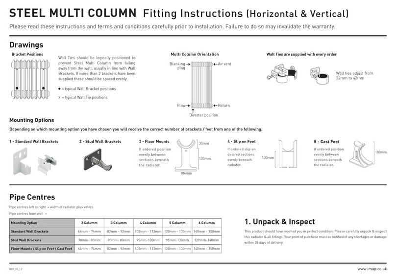
Pipe Centres
Pipe centres left to right
Pipe centres from wall
Depth from wall
Commission
7
Please Note:
In accordance with Part L1 2006 of the Building Regulations and
BS7593:1992 code of practice for the treatment of hot water
and central heating systems, we strongly recommend flushing
the heating system post installation of new radiators and then
adding the correct quantity and type of inhibitor for use with
your radiator and system to prevent corrosion. Damage caused
to systems not protected by a suitable inhibitor will not be
covered by manufacturer’s guarantee.
Width + Valves
50mm
80mm
Mark Brackets
3
You will need:
• Tape measure
• Electric drill and bits
• Spirit level
• Spanner
• Hex keys
• Radiator valves
You should have:
• 1 Radiator
• 4 Wall brackets
• 1 Air vent
• 1 Blanking Plug
• 1 Diverter
Fig.1
ISTRUZIONI PER LʼINSTALLAZIONE RADIATORE MOD. SEBINO
HOW TO INSTALL THE RADIATORS - SEBINO MODEL
160
320
480
4
6
8
elementi/sections
L1 mm
320
400
480
10
12
14
elementi/sections
L2 mm
≥ 50 mm
30 mm
Ø 8 mm
20 mm
50 mm
≥ 100 mm
≥ 100 mm
L1 L2
L2
90 mm80 mm
Fig 4.
Fig 3.
Fix brackets & Hang Radiator
4
Fig.2
ISTRUZIONI PER LʼINSTALLAZIONE RADIATORE MOD. SEBINO
HOW TO INSTALL THE RADIATORS - SEBINO MODEL
160
320
480
4
6
8
elementi/sections
L1 mm
320
400
480
10
12
14
elementi/sections
L2 mm
≥ 50 mm
30 mm
Ø 8 mm
20 mm
50 mm
≥ 100 mm
≥ 100 mm
L1 L2
L2
90 mm80 mm
ISTRUZIONI PER LʼINSTALLAZIONE RADIATORE MOD. SEBINO
HOW TO INSTALL THE RADIATORS - SEBINO MODEL
160
320
480
4
6
8
elementi/sections
L1 mm
320
400
480
10
12
14
elementi/sections
L2 mm
≥ 50 mm
30 mm
Ø 8 mm
20 mm
50 mm
≥ 100 mm
≥ 100 mm
L1 L2
L2
90 mm80 mm
38.5mm
38.5mm
ISTRUZIONI PER LʼINSTALLAZIONE RADIATORE MOD. SEBINO
HOW TO INSTALL THE RADIATORS - SEBINO MODEL
160
320
480
4
6
8
elementi/sections
L1 mm
320
400
480
10
12
14
elementi/sections
L2 mm
≥ 50 mm
30 mm
Ø 8 mm
20 mm
50 mm
≥ 100 mm
≥ 100 mm
L1 L2
L2
90 mm80 mm
Please refer to diagrams opposite when following steps below:
Place the radiator in desired position leaning against the wall.
Lightly mark the edge positions on both sides of the radiator.
Move the radiator and measure 90mm (g 4) in from each side.
Using a spirit level lightly draw a vertical line through these marks.
For top bracket positions mark the desired height of the radiator
on the vertical lines.
Measure down from the mark 38.5mm this will give the position
of the top bracket fixing point, 30mm below that is the point for
the lower fixing point on the top bracket.
Assemble bracket as per Fig 1
PLEASE NOTE: BOTTOM BRACKETS ARE SPACERS AND
NOT LOAD BEARING.
Fix top brackets and hang radiator.
Mark the position of the bottom of the radiator on the
original vertical lines .
Remove the radiator and mark 38.5mm above the mark for
the lower bracket fixing and 30mm above that for the top
bracket fixing. Assemble bracket as per fig 2.
Drop in brackets, hang the radiator on the top brackets, feel
under the radiator for the bottom brackets and push up so
that lower brackets drop down over the lower collector thus
forming spacer from wall.
Unscrew blanking plug 2 using a
12mm hex key (Fig 5) on the flow
side of the radiator.
Insert rubber diverter with a
screwdriver (Fig 6) replace the
blanking plug.
ISTRUZIONI DI MONTAGGIO DIAFRAMMA
A (fig. 1) Svitare il tappo 2 con chiave esagonale da 12 mm
B (fig. 1) Utilizzando un giravite piatto inserire il diaframma 3
(art. A052) nel foro filettato e introdurlo nel collettore fino alla
linguetta di blocco come di seguito indicato
- (fig. 2) posizione diaframma con ingresso acqua a sinistra
del radiatore o con tubazioni dal pavimento
- (fig. 3) posizione diaframma con ingresso acqua a destra
del radiatore con tubazioni dal pavimento
C Avvitare nuovamente il tappo 2 fino a completa chiusura
(20 Nm)
D Collegamento delle valvole con tubazioni dal pavimento:
rimuovere i tappi 1 e 2 (fig. 1), inserire il diaframma come
indicato al punto B per garantire la corretta circolazione del
fluido, sostituire i tappi 1 e 2 con riduzioni 3/4”-1/2” sede coni-
ca (art. A350) oppure riduzioni sede piana (art. A351)
E (fig. 4, 5) Collegare le valvole con interasse 50 mm
FIG. 1 FIG. 4 FIG. 5
FIG. 3
WATER
INLET
WATER
INLET
FIG. 2
IMPORTANTE
Qualora i radiatori Sebino con interasse
maggiore di 800 mm vengano collegati
idraulicamente con gli attacchi in basso
sui lati opposti e per tutti i radiatori instal-
lati con tubazioni dal pavimento, è neces-
sario inserire il diaframma (art. A052) fra il
primo e il secondo elemento.
ATTENTION
When Sebino radiators with pipe centres
greater than 800 mm are hydraulically
connected to the bottom connections on
opposite sides and for all radiators instal-
led with pipes from the floor, it is neces-
sary to insert the diverter (art. A052) bet-
ween the first and second section.
HOW TO INSTALL THE DIVERTER
A (fig. 1) Unscrew the plug 2 using a 12 mm hex wrench
B (fig. 1) Insert the diverter 3 (Art. A052) into the threaded hole
using a flat screwdriver and screw it into the manifold up to
the locking tab as shown below
- (fig. 2) Diverter position with water inlet to the left of the
radiator or with pipes from the floor
- (fig. 3) Diverter position with water inlet to the right of the
radiator with pipes from the floor
C Replace plug 2 and screw it into place (20 Nm)
D Connection of valves with piping from the floor: remove plugs
1 and 2 (Fig. 1), insert the diverter as shown in point B to
ensure correct circulation of the fluid, replace plugs 1 and 2
with 3/4"-1/2" conical seat reductions (art. A350) or flat seat
reductions (art. A351)
E (fig. 4, 5) Connect the valves with 50 mm pipe centres
Do not unscrew
GGLLOOBBAALLdi Fardelli O. & C. s.r.l.
via Rondinera, 51 - 24060 ROGNO (BG) Italy - gglloobbaallrraaddiiaattoorrii..iitt- [email protected] 290
450
610
770
930
1090
4
6
8
10
12
14
elementi/sections
N mm
12 mm
25 mm
50 mm
25 mm
50 mm
N
Fig 5.
ISTRUZIONI PER LʼINSTALLAZIONE RADIATORE MOD. SEBINO
HOW TO INSTALL THE RADIATORS - SEBINO MODEL
160
320
480
4
6
8
elementi/sections
L1 mm
320
400
480
10
12
14
elementi/sections
L2 mm
≥ 50 mm
30 mm
Ø 8 mm
20 mm
50 mm
≥ 100 mm
≥ 100 mm
ISTRUZIONI PER LʼINSTALLAZIONE RADIATORE MOD. SEBINO
HOW TO INSTALL THE RADIATORS - SEBINO MODEL
160
320
480
4
6
8
elementi/sections
L1 mm
320
400
480
10
12
14
elementi/sections
L2 mm
≥ 50 mm
30 mm
Ø 8 mm
20 mm
50 mm
≥ 100 mm
≥ 100 mm
L1 L2
L2
90 mm80 mm
Valve connections
6
Connections directly to Base of Radiator (6B)
Pipe centres to connect directly to the base
of the radiator would be width of radiator
less 50mm (25mm each side).
Remove blanking plug 1 (g 5) with 12mm
hex key. Use the removed blanking plugs to
blank the side connections. Screw valve tails
directly into radiator and connect.
ISTRUZIONI DI MONTAGGIO DIAFRAMMA
A (fig. 1) Svitare il tappo 2 con chiave esagonale da 12 mm
B (fig. 1) Utilizzando un giravite piatto inserire il diaframma 3
(art. A052) nel foro filettato e introdurlo nel collettore fino alla
linguetta di blocco come di seguito indicato
- (fig. 2) posizione diaframma con ingresso acqua a sinistra
del radiatore o con tubazioni dal pavimento
- (fig. 3) posizione diaframma con ingresso acqua a destra
del radiatore con tubazioni dal pavimento
C Avvitare nuovamente il tappo 2 fino a completa chiusura
(20 Nm)
D Collegamento delle valvole con tubazioni dal pavimento:
rimuovere i tappi 1 e 2 (fig. 1), inserire il diaframma come
indicato al punto B per garantire la corretta circolazione del
fluido, sostituire i tappi 1 e 2 con riduzioni 3/4”-1/2” sede coni-
ca (art. A350) oppure riduzioni sede piana (art. A351)
E (fig. 4, 5) Collegare le valvole con interasse 50 mm
FIG. 1 FIG. 4 FIG. 5
FIG. 3
WATER
INLET
WATER
INLET
FIG. 2
IMPORTANTE
Qualora i radiatori Sebino con interasse
maggiore di 800 mm vengano collegati
idraulicamente con gli attacchi in basso
sui lati opposti e per tutti i radiatori instal-
lati con tubazioni dal pavimento, è neces-
sario inserire il diaframma (art. A052) fra il
primo e il secondo elemento.
ATTENTION
When Sebino radiators with pipe centres
greater than 800 mm are hydraulically
connected to the bottom connections on
opposite sides and for all radiators instal-
led with pipes from the floor, it is neces-
sary to insert the diverter (art. A052) bet-
ween the first and second section.
HOW TO INSTALL THE DIVERTER
A (fig. 1) Unscrew the plug 2 using a 12 mm hex wrench
B (fig. 1) Insert the diverter 3 (Art. A052) into the threaded hole
using a flat screwdriver and screw it into the manifold up to
the locking tab as shown below
- (fig. 2) Diverter position with water inlet to the left of the
radiator or with pipes from the floor
- (fig. 3) Diverter position with water inlet to the right of the
radiator with pipes from the floor
C Replace plug 2 and screw it into place (20 Nm)
D Connection of valves with piping from the floor: remove plugs
1 and 2 (Fig. 1), insert the diverter as shown in point B to
ensure correct circulation of the fluid, replace plugs 1 and 2
with 3/4"-1/2" conical seat reductions (art. A350) or flat seat
reductions (art. A351)
E (fig. 4, 5) Connect the valves with 50 mm pipe centres
Do not unscrew
GGLLOOBBAALLdi Fardelli O. & C. s.r.l.
via Rondinera, 51 - 24060 ROGNO (BG) Italy - gglloobbaallrraaddiiaattoorrii..iitt- [email protected] 290
450
610
770
930
1090
4
6
8
10
12
14
elementi/sections
N mm
12 mm
25 mm
50 mm
25 mm
50 mm
N
Fig 6.
6A
6B
You can have your valves connected in two
ways; bottom opposite ends (g 6A) or to
the base of the radiator (g 6B).
Fig.1
ISTRUZIONI PER LʼINSTALLAZIONE RADIATORE MOD. SEBINO
HOW TO INSTALL THE RADIATORS - SEBINO MODEL
160
320
480
4
6
8
elementi/sections
L1 mm
320
400
480
10
12
14
elementi/sections
L2 mm
≥ 50 mm
30 mm
Ø 8 mm
20 mm
50 mm
≥ 100 mm
≥ 100 mm
L1 L2
L2
90 mm80 mm
