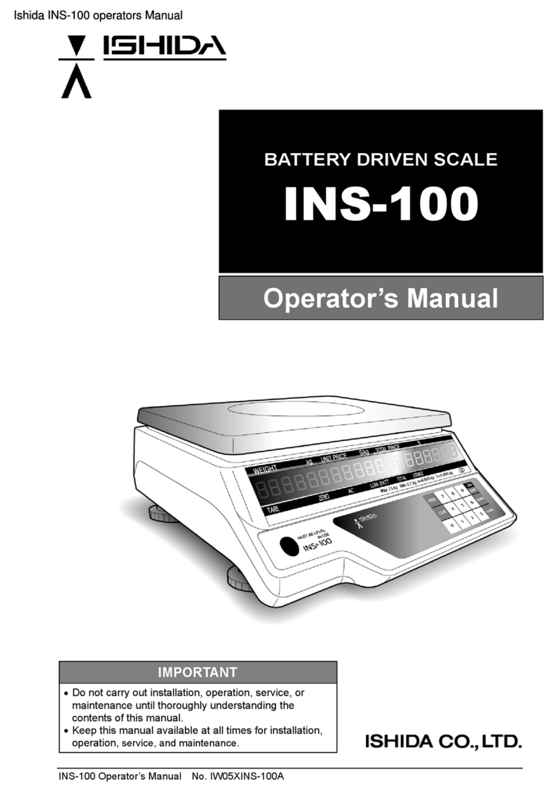
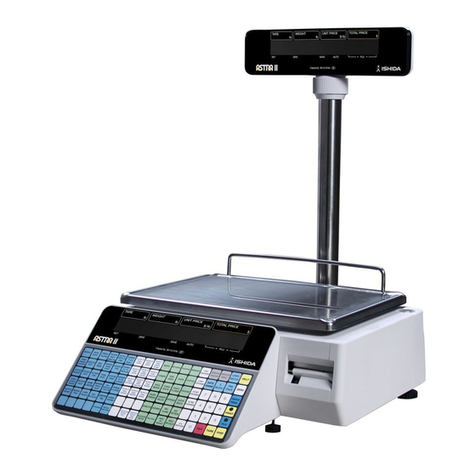
ISHIDA INS-100 User manual

INS-100 Service Manual No. 085-6692-09
BATTERY DRIVEN SCALE
INS-100
Service Manual
Second Edition
IMPORTANT
•Do not carry out installation, setup, service, or
maintenance until thoroughly understanding the
contents of this manual.
•Keep this manual available at all times for
installation, setup, service, and maintenance.

2 INS-100 Service Manual No. 085-6692-09
Revision history
Second Edition (November 2009)
1 Added ” INVALID" F2 - F15
Chapter 4.1 E2ROM Map (0 – 127) Data Format
Chapter 2.3 Items in Each Mode-Setup Mode
Chapter 2.5.3 Menu List
2 Chapter 4.2 Weighing Condition Setting Table (D008A)
Add the following
116B 1 30 Allow accumulate 0: No 1: Yes
116B 8 33 Special Price calculation 0: No 1: Yes
3 Chapter 4.4 Country Code Table (D008A)
Added Country code
© Ishida Co., Ltd. 2005 All rights are reserved.
All rights are reserved. No part of this publication may be reproduced, stored in a retrieval system, or
transmitted in any form or by any means mechanical, electronic, photocopying, recording, or otherwise
without prior written permission of Ishida. No patent liability is assumed with respect to the use of the
information contained herein. Moreover, because Ishida is constantly striving to improve its high-quality
products, the information contained in this manual is subject to change without notice. Every precaution
has been taken in the preparation of this manual. Nevertheless, Ishida assumes no responsibility for errors
or omissions. Neither is any liability assumed for damages resulting from the use of the information
contained in this publication.

IMPORTANT NOTICE
This manual explains the procedures to perform installation, setup, service, or maintenance of the
machine. Those who handle the machine must be aware of the hazards involved. These dangers may
not be obvious, so it is imperative to follow the instructions detailed in this manual when performing
installation, setup, service, or maintenance of the machine. Therefore, we recommend that you
thoroughly read and understand this manual before performing installation, setup, service, or
maintenance of the machine, and keep this manual in a safe place where you can refer to it whenever
necessary.
Safety countermeasures should be carefully considered and implemented before performing any
installation, setup, service, or maintenance procedure not specifically described in this manual or
indicated on the machine itself.
ERRORS AND OMISSIONS
The information in this manual has been carefully checked and is believed to be accurate. However,
please understand that the descriptions in this manual may not agree with the actual machine due to
machine improvements. ISHIDA assumes no responsibility for clerical, typographical or proofreading
errors, or omissions.
LIMITATIONS OF LIABILITY
ISHIDA is not liable for any damage, loss or injury that results from incorrect handling, insufficient
caution, unauthorized modifications to the machine, or failure to follow the instructions contained in
this manual.
ISHIDA assumes no responsibility for special, indirect, or consequential damages, loss of profits or
commercial loss in any way connected with the machine, whether such claim is based on contract,
warranty, negligence, or strict liability.
ISHIDA shall assume responsibility for problems with the machine based on an individual
maintenance contract. However, ISHIDA shall not be responsible for secondary problems.
ISHIDA assumes no responsibility for the user's programming of this machine, or any consequence
thereof.
In no event shall ISHIDA be responsible for warranty, repair, or other claims regarding the machine
unless ISHIDA’s analysis confirms that the machines were properly handled, stored, installed, and
maintained and not subject to contamination, abuse, misuse, or inappropriate modification or repair.
INS-100 Service Manual No. 085-6692-09 3

SAFETY CONSIDERATIONS
This service manual contains information necessary for handling the machine. It is strongly advised
that the following safety measures must be observed to ensure the safe handing of the machine:
•Servicing is to be carried out by qualified service personnel only
These service instructions are for use by qualified service personnel who fully understand the
potential hazards involved. To avoid any possible danger, do not perform any service procedures
unless qualified to do so.
•Perform only the specified service procedures
To ensure personal safety, do not perform any service procedures that are not specifically
mentioned in this manual.
•Avoid servicing while power is being supplied when using an AC power
When using an AC power, the power supply to the machine is disconnected only when the electrical
plug is removed from the electrical outlet. For protection against electrical shock, remove the plug
before performing any servicing to the machine. Servicing the machine while power is being
supplied and opening or removing covers or enclosures should be avoided as much as possible.
When servicing cannot be performed by any other means, service personnel should take
precautions against the danger of electrical shock or other potential hazards involved.
PRECAUTION SYMBOLS
The precaution symbols in this manual and precaution stickers affixed to the machine itself are divided
into three categories depending on the level of danger or seriousness of potential injury. The definition
for each of these warnings and precautions are shown below. Failure to heed these precautions may
result in bodily injury or damage to the machine.
Indicates information that, if not heeded, is likely to result in loss of life or
serious injury.
Indicates information that, if not heeded, could possibly result in loss of life or
serious injury.
Indicates information that, if not heeded, could result in relatively serious or
minor injury, damage to the machine, or faulty operation.
4 INS-100 Service Manual No. 085-6692-09

CAUTIONS FOR USE
fDo not disassemble the machine. fDo not allow any liquids to come into contact
with the machine.
fDo not drop or apply a strong shock to the
machine. fWhen cleaning the machine, only use a soft
dry cloth or a cloth wetted with a neutral
cleanser.
Never use thinner or other volatile liquids.
AC Power Supply (when used)
•Use the specified voltage after referring to
the specification plate located on the
machine.
•Use a dedicated power source.
(Voltage fluctuation may cause the machine
to malfunction)
INS-100 Service Manual No. 085-6692-09 5

CAUTIONS FOR INSTALLATION
Avoid the following areas when installing the machine
•Areas subject to high temperatures or high
humidity
•Areas exposed to direct sunlight
•Areas where water or other liquids are
easily spilled on the machine
•Areas subject to excessive vibration or
unstable surfaces
•Areas exposed to direct cold air
•Areas subject to low temperatures
•Areas subject to a lot of dust or dirt
•Areas with large voltage fluctuations •Areas where the scale is not level
Level adjustment
•Always ensure that the machine is level. If the machine is not level, weighing may not be accurate.
•Adjust the machine to a level position using the four level adjustment feet located on the button of
the machine, until the bubble is completely centered in the round level indicator.
6 INS-100 Service Manual No. 085-6692-09

INS-100 Service Manual No. 085-6692-09 7
TABLE OF CONTENTS
1. PRODUCT OVERVIEW..........................................................................................9
1.1 Front View ......................................................................................................... 9
1.2 Rear View........................................................................................................ 10
1.3 Operating Panel............................................................................................... 10
1.4 Basic specifications ..........................................................................................11
2. SETUP PROCEDURE..........................................................................................12
2.1 Check Flow...................................................................................................... 12
2.2 Various Modes................................................................................................. 12
2.3 Items in Each Mode......................................................................................... 13
2.4 Voltage Check Mode........................................................................................ 14
2.5 Setup Mode..................................................................................................... 15
2.5.1 Entering Setup Mode .............................................................................. 15
2.5.2 Key Operation......................................................................................... 15
2.5.3 Menu List................................................................................................. 16
2.6 Test Mode........................................................................................................ 17
2.6.1 Entering Test Mode ................................................................................. 17
2.6.2 Key Operation......................................................................................... 17
2.6.3 Scale Adjustment (C1 Mode)................................................................... 18
2.6.4 Key Check (C2 Menu)............................................................................. 21
2.6.5 Display Check 1 (C3 Menu) .................................................................... 21
2.6.6 Display Check 2 (C4 Menu) .................................................................... 22
2.6.7 Software Number Display........................................................................ 22
2.6.8 RAM/E2ROM Clear (C6 Menu)............................................................... 23
2.6.9 Weighing Conditions for Each Country (C7 Menu).................................. 24
2.6.10 E2ROM Data Read (C8 Menu) ............................................................... 25
2.6.11 Memory Button........................................................................................ 26
3. COMPONENT REPLACEMENT ..........................................................................27
3.1 Removing the Upper Case .............................................................................. 27
3.2 Replacing the Display Unit (PS-030) ............................................................... 27
3.2.1 Operator Display Unit.............................................................................. 27
3.2.2 Customer Display Unit ............................................................................ 28
3.3 Replacing the Main Board (PS-031)................................................................ 28
3.4 Replacing the Load Cell Unit........................................................................... 29
3.5 Replacing the Transformer .............................................................................. 30
3.6 Replacing the Battery ...................................................................................... 31
4. REFERENCE DATA .............................................................................................32
4.1 E2ROM Map (0 - 127) Data Format................................................................. 32
4.2 Weighing Condition Setting Table (D008A)...................................................... 33
4.3 Weighing Capacity Number Table.................................................................... 35
4.4 Country Code Table (D008A)........................................................................... 36

5. DIAGRAMS ..........................................................................................................37
5.1 External Dimensions........................................................................................ 37
5.2 Exploded Diagram........................................................................................... 38
5.3 Parts List.......................................................................................................... 40
5.4 Block Diagram ................................................................................................. 41
5.5 Main Board Circuit Diagram............................................................................. 42
5.6 Display Board Circuit Diagram......................................................................... 43
5.7 Key Board Circuit Diagram.............................................................................. 43
6. TROUBLESHOOTING..........................................................................................44
8 INS-100 Service Manual No. 085-6692-09

Chapter 1 PRODUCT OVERVIEW
1. PRODUCT OVERVIEW
1.1 Front View
Weigh platter Operator display
Upper case
Operating panel
Lower case
Height adjustment foot
Level Keys
INS-100 Service Manual No. 085-6692-09 9

Chapter 1 PRODUCT OVERVIEW
1.2 Rear View
Customer display
1.3 Operating Panel
Level
guide
10 INS-100 Service Manual No. 085-6692-09

Chapter 1 PRODUCT OVERVIEW
1.4 Basic specifications
Items Contents
Weighing capacity 15kg single range (15kg / 0.005kg)
6kg single range (6kg / 0.002kg)
Lineup Standard type / Pole installation type
Use conditions Temperature: Between –10°C and 40°C
Humidity: 85% (max.) without condensation or freeze
Main body: Resin (ABS)
Pole type display: Resin (ABS)
External material
Weigh platter: Stainless steel (SUS304)
External size Standard type: 310(W) × 310(D) × 110(H)mm
Pole type: 310(W) × H340(D) × 400(H)mm
Weigh platter Flat plate: W300(W) × 200(D)mm
Display Red LED display (Same contents on both operator and rear/pole displays)
Numeric display: 7segment LED (16 digits)
Weight: 5 digits, Unit price: 5 digits, Total price: 6 digits
Indicator: 6 round LED’s
TARE, ZERO, AC, BATTERY LOW, TOTAL, STABLE
Decimal point: Period type
Keys Tact key: 16 pieces
Operation key: 15 pieces
Span storage key: 1 piece (inside)
Load cell 25kg or 30kg: 350 Ω(15kg specification)
10kg: 350 Ω(6kg specification)
Power supply AC110V/220V, 50Hz
(Can be driven by the rechargeable lead storage battery: option)
Main functions 1/4 and 1/2 price key function
Auto power OFF function
“lb” / “kg” change function
Weight only display function
Total function
Option None
INS-100 Service Manual No. 085-6692-09 11

Chapter 2 INSTALLATION & SETUP
2. SETUP PROCEDURE
2.1 Check Flow
Power ON ON/OFF key All segments blink. Initial display appears.
¾
Key check Each key can be checked.
¾
Weighing capacity check Amaximum weight can be checked.
¾
Battery voltage check Current voltage level can be checked.
¾
Auto power function check Auto power function can be checked.
¾
Country setting check Country setting and weighing conditions can be checked.
¾
Power OFF ON/OFF key
2.2 Various Modes
Scale ON
Test Mode
Setup Mode
Voltage Check Mode
Normal Mode
TARE
CLR
1
Start
Checking
ON/
OFF
12 INS-100 Service Manual No. 085-6692-09

Chapter 2 INSTALLATION & SETUP
INS-100 Service Manual No. 085-6692-09 13
2.3 Items in Each Mode
Normal Mode ON/OFF key
Weight, Unit price, and Total price
display
Zero point adjustment
Tare weight subtraction
Unit price input or cancellation
Price addition function
Voltage Check Mode ON/OFF key TARE key
Battery level check Current voltage level can be checked.
Setup Mode ON/OFF key CLEAR key
F 1 Automatic power OFF change function
F 2 Invalid (Automatic preset call function)
F 3 Invalid (Digit number change) (Printer specification)
F 4 Invalid (Date print) (Printer specification)
F 5 Invalid (Preset number print) (Printer specification)
F 6 Invalid (Upper/Lower tare print) (Printer specification)
F 7 Invalid (Serial number print) (Printer specification)
F 8 Invalid (Continual/Single label
specification) (Printer specification)
F 9 Invalid (Baud rate) (RS-232C)
F10 Invalid (Serial output message
specification) (RS-232C)
F11 Invalid (Serial output method) (RS-232C)
F12 Invalid (Serial output condition) (RS-232C)
F13 Invalid (Output signal setting) (Contact point box)
F14 Invalid (Input signal setting) (Contact point box)
F15 Invalid (Large volume buzzer)
F16 Built-in buzzer output condition
F17 Automatic power OFF function existence setting
Note: F2 – F15 is Invalid function.
Test Mode ON/OFF key [ 1 ] key
C 1 Scale adjustment (country code, weighing capacity, area,
zero, span)
C 2 Key check
C 3 Display check 1 (simplified check)
C 4 Display check 2 (detailed check)
C 5 Program number display
C 6 RAM and E2ROM clear
C 7 Country specification/Weighing condition settings
C 8 E2ROM data read

Chapter 2 INSTALLATION & SETUP
2.4 Voltage Check Mode
Press the [ON/OFF] key to turn ON the machine, and immediately keep pressing the [TARE] key until
the following “BATT CHECK” display appears.
6.8V or more
6.6V or more
6.4V or more
6.2V or more
6.0V or more
Voltage level
6.0V or less (Charge is required)
Note: To exit this mode, press the [CLEAR] key.
14 INS-100 Service Manual No. 085-6692-09

Chapter 2 INSTALLATION & SETUP
2.5 Setup Mode
2.5.1 Entering Setup Mode
Press the [ON/OFF] key to turn ON the machine, and immediately keep pressing the [CLEAR] key
until the following “FUNC” display appears.
Set value
Menu number.
2.5.2 Key Operation
• Used to advance a menu number.
• Used to increase a set value.
• Used to decrease a set value.
• Used to finish current menu.
ADD
ZERO
TARE
CLR
INS-100 Service Manual No. 085-6692-09 15

Chapter 2 INSTALLATION & SETUP
16 INS-100 Service Manual No. 085-6692-09
2.5.3 Menu List
No. Content Setup Value
F 1 Automatic power OFF function 0: Power OFF after a certain period of time.
1: Unit price and price display disappears after a certain
period of time (depending on country setting)
F 2 Invalid
(Preset automatic call function) 0: Invalid 1: Invalid
F 3 Invalid (Digit number change )
(when the printer is connected) 0: Invalid 1: Invalid
F 4 Invalid (Date print)
(when the printer is connected) 0: Invalid 1: Invalid
F 5 Invalid (Preset number print)
(when the printer is connected) 0: Invalid 1: Invalid
F 6 Invalid
(Tare and upper/lower limit print)
(when the printer is connected)
0: Invalid 1: Invalid
F 7 Invalid (Serial number print)
(when the printer is connected) 0: Invalid 1: Invalid
F 8 Invalid (Continual labels/Single
label specification)
(when the printer is connected)
0: Invalid 1: Invalid
F 9 Invalid (Baud rate) (RS-232C) 0: Invalid 1: Invalid 2: Invalid 3: Invalid
4: Invalid 5: Invalid
F10 Invalid
(Serial output message
specification) (RS-232C)
0: Invalid 1: Invalid 2: Invalid 3: Invalid
4: Invalid 5: Invalid
F11 Invalid
(Serial output method ) (RS-232C) 0: Invalid 1: Invalid 2: Invalid 3: Invalid
F12 Invalid
(Serial output
condition)b(RS-232C)
0: Invalid 1: Invalid 2: Invalid 3: Invalid
4: Invalid 5: Invalid 6:Invalid 7: Invalid
F13 Invalid
(Contact output signal setting) 0: Invalid 1: Invalid 2: Invalid 3: Invalid
F14 Invalid
(Contact input signal setting)
(Contact point box)
0: Invalid 1: Invalid 2: Invalid 3: Invalid
F15 Invalid (Large volume buzzer) 0: Invalid 1: Invalid 2: Invalid 3: Invalid
4: Invalid 5: Invalid
F16 Built-in buzzer output condition 0: Operation 1: Non-operation
F17 Automatic power OFF time setting
0: No function 1: 10 minutes 2: 20 minutes
3: 30 minutes 4: 40 minutes 5: 50 minutes
6: 60 minutes 7: 0.5 minutes 8: 1 minute
9: 5 minutes
Note: To exit this mode, press the [CLEAR] key.
F2 – F15 is Invalid function.

Chapter 2 INSTALLATION & SETUP
2.6 Test Mode
2.6.1 Entering Test Mode
Press the [ON/OFF] key to turn ON the machine, and immediately keep pressing the [ 1 ] key until
“C1” display appears.
2.6.2 Key Operation
• Used to move to the next menu.
• Used to move menus in ascending order like C1C2 C3 C8.
• Used to increase a set value
• Used to move menus in descending order like C8 C7 C6 C1.
• Used to decrease a set value.
• Used to return the display to the first step of current menu.
ADD
ZERO
TARE
CLR
INS-100 Service Manual No. 085-6692-09 17

Chapter 2 INSTALLATION & SETUP
2.6.3 Scale Adjustment (C1 Mode)
Scale adjustment (country code, weighing capacity, area, zero, span)
Operation Display
• Confirm that the “C1” menu is displayed.
• Press the [ADD] key to move to the country
code setting menu (C1-1).
• Press the [ZERO] or [TARE] key to increase
or decrease the set value.
Note: Refer to “Country Code Table” in Chapter 4.
• If the memory button is pressed at this point,
“STORE OK” display will appear.
(Refer to Section 2.6.11 in this Chapter)
• Press the [ADD] key to move to the weighing
capacity setting menu (C1-2).
• Press the [ZERO] or [TARE] key to increase
or decrease the set value.
Note: Refer to “Weighing Capacity Number Table” in
Chapter 4.
• If the memory button is pressed at this point,
“STORE OK” display will appear.
(Refer to Section 2.6.11 in this Chapter)
• Press the [ADD] key to move to the area
setting menu (C1-3). (Not used)
• Press the [ZERO] or [TARE] key to increase
or decrease the set value.
• Press the [ADD] key to move to the zero point
adjustment menu (C1-4).
• Press the [ZERO] or [TARE] key to increase
or decrease the set value.
18 INS-100 Service Manual No. 085-6692-09

Chapter 2 INSTALLATION & SETUP
• Press the [ADD] key to move to the span
condition adjustment menu (C1-5).
• Press the [ZERO] key and confirm that the
A/D value shows “5000" and the value for
internal inspection shows within the range.
• Place weights that are equivalent weight to
the weighing capacity on the weigh platter.
• Press the [TARE] key to execute span
adjustment.
• Remove weights from the weigh platter.
Value for internal
inspection
A/D value
INS-100 Service Manual No. 085-6692-09 19

Chapter 2 INSTALLATION & SETUP
• If the memory button is pressed at this point,
“STORE OK” display will appear.
(Refer to Section 2.6.11 in this Chapter)
• Press the [CLEAR] key to return to the C1-5
menu.
20 INS-100 Service Manual No. 085-6692-09
Other manuals for INS-100
2
Table of contents
Other ISHIDA Scale manuals

ISHIDA
ISHIDA CWS-02 Quick guide

ISHIDA
ISHIDA SR-2000 alpha Manual

ISHIDA
ISHIDA SR-2000 alpha User manual

ISHIDA
ISHIDA Astra User manual

ISHIDA
ISHIDA IWX-150/30 User manual

ISHIDA
ISHIDA IWQ Series User manual

ISHIDA
ISHIDA IP-AI User manual

ISHIDA
ISHIDA IP-EMZ User manual

ISHIDA
ISHIDA MTE-300 User manual

ISHIDA
ISHIDA IWB Series User manual

ISHIDA
ISHIDA Uni-5 User manual

ISHIDA
ISHIDA AC-4000 Series User manual

ISHIDA
ISHIDA UNI-7 User manual

ISHIDA
ISHIDA AC-4000B User manual

ISHIDA
ISHIDA UNI-7 User manual

ISHIDA
ISHIDA NOVA-II User guide

ISHIDA
ISHIDA Astra Instruction Manual

ISHIDA
ISHIDA Uni-3 User manual

ISHIDA
ISHIDA SR-2000 alpha User manual

ISHIDA
ISHIDA AC-4000H User manual