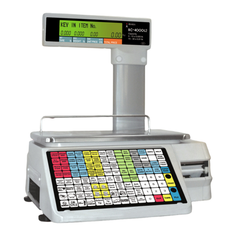
ISHIDA AC-3000 User manual

SYSTEM SETUP
MANUAL
ISHIDA
CO.,
LTD.
REVISION
0

............................
i
BLANK
PAGE
i
............................
AC-3000
SYSTEM SETUP REV
0

TABLE OF CONTENTS
1.1 INTRODUCTION
...........................................................
1-1
1.2 PARTS REQUIREDFOR MOUNTING
..........................................
1-2
1.3 OPTIONS
...........................................................
1-2
..........................................................
1.4 MASTER BOARD 1-3
2.1 MASTER SCALE PROCEDURES
..............................................
2-1
2.2 SATELLITE SCALE PROCEDURES
.............................................
2-2
2.3 MASTER BOARD (P-835) ATACHMENT
.......................................
2-3
2.4
12
NETCABLE CONNECTION METHOD
.......................................
2-5
2.5
12
NETCABLE CONNECTORS
................................................
2-5
3.1 MENU SCHEMATIC
.......................................................
3-1
3.2 MENUSELECTION METHODS
..............................................
3-2
3.3 SALES MODE(COB)
........................................................
3-2
3.4 MASTER BOARD HARDWARE TEST (C101)
...................................
3-3
3.5 MASTER BOARD RAMCLEAR (C102)
........................................
3-4
3.6 MEMORYCHECK
.......................................................
3-4
3.7 MASTER BOARD DATA SDILD (C199)
........................................
3-5
14
1
Registration
Mode
1
4.1 SYSTEM EXPANSIONMODE
................................................
4-1
4.2 MACHINE NO
.
(P17)
.......................................................
4-2
4.3 lNLlNEREGISTRATION(P19)
................................................
4-2
4.4 MASTER MAINTENANCE (P2O)
..............................................
4-3
15
1
Setup
Error
Messages
:
. .
5.1 ERROR MESSAGE HANDLING
..............................................
5-1
......
16
1
Electrical
Diagrams
. . ..
6.1 BLOCKDIAGRAM
........................................................
6-1
..................................................
6.2 CONNECTION DIAGRAM 6-2
CCW-RZ
o
OPERATION
a
REV
O
Table
of Contents-1
............................
BLANK
PAGE
i
............................
AC-3000
SYSTEM SETUP
a
REV
0

a
ExternalView
SCALE
#1
(MASTER)
SCALE
#2
(SATELLITE)
SCALE
#3
(SATELUTE)
SystemConfiguration
The AC-3000lAC-3000E inline scale system allows connection of multiple dual-
displayscales toconformwith user's site requirements.
Notethat the master scale must be an AC-3000 unit, while the connected satellites
maybe either AC-3000 or AC-3000E.
System Limit
A maximum oftwenty AC-3000/AC-3000Eunits can be connected inone system.
Master BoardAddition
For this system, an P-835 Master board must be installed inthe master scale. Please
refertopage
2-3
for master board installation instructions.
System ConnectionMethod
All units are connected by
I2
NET cables. Please refer topage 2-5 for
I2
NET cable in-
stallation instructions.
AC-3000
SYSTEM SETUP REV
0

AC-3000
SYSTEM SETUP OVERVIEW
................
1.
AC-3000lAC-3000E MainUnits Required unitcount
....
2.
Function ExpansionAccessory
Kit
(Part No41-7410-03) Oneset
[Kit
includesthefollowing parts]
.....................
Master board(P-835) 1
...............................
Guide rails 2
...................................
Collar 1
M3screw
................................
1
.................................
Harness 1
..........................
RS-232C Harness 1
..................................
Bracket 1
...........................
He-xconnectors 2
..................................
Sticker 1
3. Program
ROM
Mainboards (For master
&
satellitescales)
.
.
Scale count
Master board (For masterscale only)
.......
1
4.
12
NET Cable
...............
Master board program ROM
1
5. RequiredInstruction Manuals
This manualandtheAC-3000lAC-3000E Service Manuals
One optional
12
NETcable can beused for system expansion.
Required Parts
HarnessC2 I2 NET (Part No. 36-3364-08)
Hexscrew rods (Part No.39-4383-04)
IMPORTANT!
The
12
NET cable cannot be connected until after thefunction expansion accessory
kit(Part No41-7410-03) has beeninstalled.
AC-3000
SYSTEM
SETUP
REV0

AC-3000
SYSTEM
SETUP
OVERVIEW
1.
Overview
The P-835 master board
is
an optional circuit board with
a
V-40 type CPU which can
be installed inthe main body of an AC-3000 scale to expand
it's
functions. Notethat
this boardcannotbeusedwiththe AC-3000E.
2.
Application
AC-3000 Series
Memoryexpansion
(1
Mbyte)
I2
NET expansion(expandable by one channel only)
Scale controller for master/satellite connection
PLEASE
NOTE:
The lithiumbattery cannot be recharged.
The normalvoltage ofthe lithium battery
is
3.6V.
\
AC-3000
SYSTEM SETUP REV
0
\
BAlTERY
SWITCH
\
\
I
n
I
\,-
-\
EP-ROM
LITHIUM
BAnERY
H27C4001
G
(4M
MPE)
\
\
J1
J2
(OPTION)
J3
(TO
16
ON
AC-3000
MAIN
BOARD)
(USED
WITH
RS-232C)
TO
DSUB
25P
FEMALE
TERMINAL

This chapter describes proceduresfor setting upthe masterlsatellitescale system.
IMPORTANT!
Before starting systemsetup, theProgram ROMmustbereplaced.
Mountthe Masterboard(P-835).
After confirmingthatthemainbody power is OFF, attachthe Master board.
For attachmentprocedure, refertoPage 2-3.
Turn the mainbody power ON, andperformRAMClear.
For RAMClear procedure, refer to
AC-3000lAC-3000E Service manual (Chapter
55: RAMClear
--
CO2).
Set Sales Mode.
Set +CSIS MODE item to
[2:
Master]. For CSlS Mode setting (C08-02) refer to
page 3-2.
Check Master boardfunction.
MasterBoardHardwareCheck
:
MasterboardHardwareTest(C101)
Ref: Page 3-3
MasterBoardRAMClear
:
MasterboardRAMClear (C102)
Ref: Page 3-4
MasterBoardMemoryCheck
:
MasterboardMemoryCheck (C105-00)
Ref: Page 3-4
When DataCommunication
is
performed(Using IF-21FD)
Perform
this
functionvia Master Board Data SDILD andDataSDILD (Test mode).
Please refer to Master Board Data SDILD (C199) onpage 3-3. For [Data SDILD]
refer tothe AC-3000lAC-3000E Service manual, Test mode99: Data SDILD.
Communication
with
Master Board
PerforminTest Mode: Master BoardData SDILD (C199).
Communication
with
Main Body(StandAlone)
PerforminTest Mode: DataCommunication (C99).
Please refertoMaster BoardData Communication (C199) on page 3-5. For [Da-
ta Communication] refer tothe AC-3000lAC-3000E Service manual, Registration
mode, Master maintenance (P2O).
IMPORTANT!
Another method of Master data communication is via Master main-
tenance (Registration mode).
For more detailed information related toMaster data, Please see Reaistration mode
instructionson
in
Chapter 4.
d
AC-3000
SYSTEM SETUP REV
0

2
SETUP PROCEDURES
1.
Turn themain body power
ON,
and perform RAM Clear
For RAM Clear procedure, refer
to
AC-3000lAC-3000E Service manual (Chapter
55: RAM Clear
--
COZ).
2. SetSales Mode
Set +CSIS MODE item
to
[3:
Satellite].
3. Register Machine Number
For Machine registration procedure, refer to AC-3000lAC-3000E Operation
manual, Machine No. Setting (Registration Mode
--
P17).
IMPORTANT!
If thesamemachine number is not registered thesystem will not func-
tion correctly. Also, if normal mode operations are performed before the machine
numbeiis registered,correct function will not bepossible.
I
When Data Communication
is
performed (Using IF-21FD)
Perform this function via Master Board Data Communication and Data Communica-
tion (Test mode).
Please refertoMaster Board Data SDILD (C199) on page3-5. For [Data Commu-
nication] refer to the AC-3000lAC-3000E Service manual, Test mode 99: Data
Communication.
PLEASE NOTE:
Another method of Master data communication is via Master main-
tenance (Registration mode).
For more detailed information related to Master data, Please see Registration mode
instructions in Chapter
4.
AC-3000
SYSTEM
SETUP
REV
0

2
SETUP PROCEDURES
CAUTION!
Before attempting to mountthe master board, turn off the main power of the AC-
3000 and unplug
its
powercord.
Notethatthe cover of the operation panel must be removed before performing
the installation.(Forremoval proceduresee theAC-3000lAC-3000EService man-
ual.
Procedure
Attach bothguide railstothetwoAC-3000 boardbrackets.
Slide the master board into the guide rails, then affix the master board to the
AC-3000 boardbracketsusingthe M3screw
(L=
10)andthe collar.
Connectthe harness to the master board
J3
(7 pin) connector and the AC-3000
main board (P-834)J6
(7
pin)connector.
Connectthe DSUB (25p) harness tothe master board
I1
connector, then attach
the DSUB (25p)(female)tothe connector bracket.
N
0
TES:
Refer tothe AC-3000 Service manual for detailed instructions on main body as-
sembly and disassembly.
After installingthe master board, pleaseset on the master board battery switch
to
ON.
AC-3000 SYSTEM
SETUP
REV0

2
SETUP
PROCEDURES
MASTER BOARDATTACHMENT
M3SCREW
MASTER BOARD GUIDE
RAIL
COLLAR BRACKET
AC-3000 MAINBODY
DSUB (SSPIN)HARNESS CONNECTION
I
DSUB (25P) (FEMALE)
I
DSUB (2SP)
HARNESS
MAIN
BOARD (P-834)
1
16 (7PIN)
HARNESS
'i
MASTER BOARD (P-835)
---/
13 (7 PIN)
AC-3000 SYSTEM SETUP
r
REV
0

2
SETUP PROCEDURES
SCALE
#I
(MASTER)
SCALE
#2
(SATELLITE)
SCALE
#3
(SATELLITE)
CONNECT
THE
12
NET
CABLES
TO
EITHER
UPPER
OR
LOWER
12
NET
CONNECTORS.
SG =Signal ground
FG =Frame ground
DSUB CONNECTOR (9P) DSUB CONNECTOR (9P)
NOTE:
The currently used I2 NET cable
is
thesame as for previousspecifications.
12
netcable (Ishida AWG28X2P, UL2464SB: PartNo. 09-8718-05 2OOm)
12
NET connector case (HDE-CTH; PartNo. 03-6924-05)
12
NET connector (HDEB-9P; Part No. 01-7109-05)
8
9
2-
5
AC-3000
SYSTEM SETUP
REV
0
---
-
DATA
8
---
--
9 DATA

[I
Test Mode
I/
I
Sub
Menus
/
I
I
-
To Access Test Mode:
Turn onthepowerswitch while holdingdownanykey;
Test mode
will
becalled up.
01
02
I
Master BoardRAM
O2
1
clear
NOTES:
For Test mode C01-C07 setting procedures, refer totheAC-3000lAC-3000E ser-
vice manual.
Instandard specifications, there is no(01 Data SDILD] inTest mode099. Instead,
use [02, Transfer file].
'-
Mode
CSlSMode
01
02
107
/
Master Board
HardwareTest
AC-3000
SYSTEM
SETUP
REV
0
12
NetRAMCheck
LoopBackTest
I
I
01
02
01
02
(~08)
03
04
05
Initialize Master Board RAMClear
lnit~alizeMaster BoardTest Data
(cl02)
(cl
02-")
Select IF21 File No.
Send
03
04
05
(c08-**)
--
12
NetProgramNo.
I2
NET Check
--
ROM
Version
(c105)
Receive
Verify
Delete
02
I
~ransier.
(~101) (~101-**) (~101-04-**)
(c099-01**)
-v
02
(
Send
03
1
Receive
03
1
Initialize Disk
(c99-**)
04
05
lg9
Verify
Delete
Master BoardData
SDILD
(~199-01"")
(c199-*')

3
TEST
MODE
PROCEDURES
This section describestheproceduresforselecting the rootand sub menus.
a
RootMenuSelection Procedure
Enterthenumberof theRoot menutobedisplayed, then press
q
4.
Press
q
4
onthesetting modedisplaytoswitchtherootmenus insequence.
Sub Menu Selection Procedure
Press
ENTER
ontherootmenudisplay.
Enterthenumber ofthesub menutobedisplayed,then press
q
4
.
Press
q
5.
toswitchthesub menus insequence.
NOTE:
Press OENo toreturntothemodedisplays.
CSlS Mode
(C08-02)
This itemdefines whether the
scale
is
used as a stand alone unit
or is linkedtoasystem as a
master or satellitescale.
Enterthe number corresponding
tothedesired mode,then press
0
ENTER.
I
2
1
Master
I
Entry Number
1
3
I
Satellite
CSlS Mode
Alone (Standalone)
Default Setting:
[I]
CSlS
MODE
1:
ALONE
(1)
CSlS MODE ENTERED
NUMBER
PLEASE NOTE:
When the initial setting of [I]
is
in effect, Test Mode items [C101],
[C102], [C103], [C105] and [C199] are notdisplayed. To display these items, select
[2] (Master).
AC-3000 SYSTEM SETUP
REV
0

3
TEST MODEPROCEDURES
0
12
NetCheck (C101-04)
This item
is
used toverifijthat
I2
Net
is
functioning normally.
r
12
Net
RAM
Check (C101-04-01)
Press
OPRINT.
Confirmthat [PASS]
is
displayed.
I/
12 NET RAMCHECK [PRINT] [OK]
ClO1-04-01 PASS
r
Loop BackTest (C101-04-02)
Press
0
PRINT.
Confirmthat[PASS]
is
displayed.
I
I
LOOP BACK TEST [PRINT] [OK]
I
1
1
c101-04-02 PASS
1
I
r
12
NetProgram No. (C101-04-03)
The
12
Net Program No. (version)
will
bedisplayed.
12 NET PROGRAM
NO.
Ver
4
Program No. (C101-05)
This item
is
used todisplay the
RQM
version number
of
themaster board.
I
[*
MASTERBOARD Ver 80170
I
I
AC-3000 SYSTEM
SETUP
REV
0

3
TEST MODE PROCEDURES
0
InitializeAllRAM onMaster Board
(C102-01)
INITIALIZEALL RAM
ON
MASTER
[OK]
This item
is
used clear all RAM data.
0
Test Set (C102-02)
This item
k
usedtowrite test data
to RAM.
Press
UZERO
twice. WhenTest
Data has been registered, [OK]
will be displayed.
Press
CIZERO
twice. When all RAM da-
ta has been cleared, [OK]will be dis-
*
MASTER BOARDTEST DATA SET
[OK]
C-
102-0
1
0
1
PLEASE
NOTE:
For test mode setting, in order tocreate a dummy data file, RAM
Clear must always be performed after thefunction test is completed.
played.
k
.
This item
is
used to confirm the
amount of total and remaining
memory in kilobytes.
I
/
*
MEMORY
lO24KB
REMAIN
995KB
1
I
AC-3000
SYSTEM
0
SETUP
REV
0

3
TEST
MODE
PROCEDURES
Data
SD/LD
is
usedfor data communicationwith an IF-21FD interface unit.
Preparation
Before attemptingtotransmit data, makesure theAC-3000/AC-3000E
is
connected
tothe IF-21FDunit, andthescale and IF-21FDpowerswitches are
ON.
Ail IF-21FD operations can bebe performedfromtheAC-3000lAC-3000E
side (thesame
as
for the previous 15-21FX unit).
Transfer Fiie(C199-02)
Transfer Fiie
is
used to transmit individ-
ualdata files.
M
Select IF-21
file
No. (C199-02-01)
SELECT
IF21
FILE
NO.
(0)
Enterthe number corresponding tothe
desired file number
(1-8),
then press
0
ENTER.
(
c199-02-01
NO
0 0
Send (C199-02-02)
FILE
ENTERED
NUMBER
NUMBER
This item
is
usedtotransmit data from
I
/
SEND
-1:
ALL
FILES
the scale toan IF-21FD interface unit.
To starttransmission, press
o
PRINT.
Enter the number corresponding to
thefile(s) tobesent, then press
1
Entry
No.
1
FileType
I
C199-02-02
No
0 0
All Files
E2
ROM
File
0
ENTER.
I
I
ENTERED
NUMBER
AC-3000
SYSTEM SETUP
9
REV
0

3
TEST MODEPROCEDURES
a
Receive (C199-02-03)
This item
is
used toreceive data from
anIF-21
FD
interface unit.
Enterthe numbercorrespondingto
thetypeoffile(s) tobereceived, then
press
0
ENTER.
To startreception, press
0
PRINT.
I
RECEIVE
-+
1:
ALL FILES (0)
/
I
EntryNo.
1
Function
11
Entry No.
(
Function
1
1
2
3
/
E2ROM File
1
6
I
coupon
11
16
/
Group
I
All Files
Master File
11
12
I
I
I
I
Ad Message
Operator Master Unit price RevisionFile
PresetKey
Setup File
Scroll Messaae
13
14
5
/
Store Master
1
10
1
Label Format
I(
20
(
Sub Total
1
Tax Master
Title File
15
I
De~artment
Verify (C199-02-04)
This item
is
used to compare IF-
21FD and
AC-3000
data.
Enterthe numbercorresponding
tothefile(s) tobe compared,
then press
0
ENTER.
To execute, press
0
PRINT.
VERIFY
-+
:
ALL
FILES (0)
I
1
Function
All Files
E2ROM File Tax Master
4
5
6
7
8
AC-3000
SYSTEM
SETUP
REV
0
9
10
Item Master
Store Master
Coupon
Ad Message
Operator Master
Preset Key
--
Label Format
14
15
16
17
18
Title File
Departmerit
Group
Campaign File
Unit priceRevisionFile
19
2
0
Receipt BarCodefile
Sub Total

3
TEST MODEPROCEDURES
a
Delete
(C199-02-05)
This item
is
usedtodeleteallfiles.
Press
OZERO
twice. Allfiles
will
be
deleted.
DELETE
il
AC-3000
SYSTEM
SETUP
REV
0

:
lnline registration(P19) and Master Maintenance (PZO) have been added. Machine
No.(~17)hasbeenincludedherefor reference.
Menu
NO.
1
Description
1
Parameters
PI7
I
Machine No.
/
Machine number
Master
Maintenance
lnline
/
Registration
I
PZO-01
1
ITEM
I
I
Defineswhether or notthere
areinlineconnections
I
PZO-02
/
STORE
1
I
PZO-03
/
COUPON
I
Copy
data
to
satellite scale
toexecute.
I
PZO-08
I
PRESET
I
I
PZO-15
I
SUB TOTAL
I
Entry Contents
1
:
Master
2-99
:
Satellite
0
:
Offline
I
:
lnline
Press
CICOPY
to
execute.
AC-3000
SYSTEM
8
SETUP
8
REV
0
This manual suits for next models
1
Table of contents
Other ISHIDA Scale manuals

ISHIDA
ISHIDA AC-4000B User manual

ISHIDA
ISHIDA AC-2000 User manual

ISHIDA
ISHIDA UNI-7 User manual

ISHIDA
ISHIDA IGX Series User manual

ISHIDA
ISHIDA UNI-7 User manual

ISHIDA
ISHIDA IP-AI User manual

ISHIDA
ISHIDA BC-4000 User manual

ISHIDA
ISHIDA IGB-60 User manual

ISHIDA
ISHIDA BC-300 User manual

ISHIDA
ISHIDA NOVA-II User guide

ISHIDA
ISHIDA SR-2000 alpha User manual

ISHIDA
ISHIDA IPC-WP User manual

ISHIDA
ISHIDA SR-2000 alpha User manual

ISHIDA
ISHIDA Astra II Bench Installation manual

ISHIDA
ISHIDA IWX-150/30 User manual

ISHIDA
ISHIDA Uni-5 User manual

ISHIDA
ISHIDA BC-3000 User manual

ISHIDA
ISHIDA IWQ Series User manual

ISHIDA
ISHIDA MTE-300 User manual

ISHIDA
ISHIDA INS-100 User manual