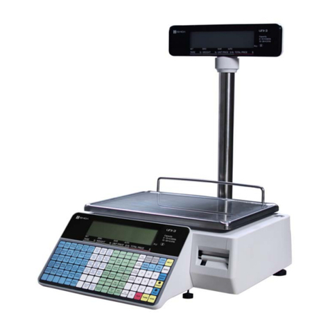
ISHIDA AC-2000 User manual

ISHIDA SCALES MFG.CO., LTD.
44
SANNO-CHO SHOGOIN SAKYO-KU KYOTO
606
JAPAN
REVISION
0

Youcan help improve this manual by calling at-
tention to errors and recommending improve-
ments. Please convey your comments to the
nearest Ishida Scales regional representative.
Thank
You!
Copyright0
1991
by
lshida Scales
Mf
.
Co., Ltd.
All
Rights Reserved.
No partofthis manual may be repro
d
uced inany form, by mimeograph or any
other means,without permission inwriting fromthe publisher.

TABLE OF CONTENTS
H1 INTRODUCTION
1.1 External Views
1.2 Dimensions
1.3 Features
1.5 Key Switch and Reset Key
H2 MECHANICAL CONFIGURATION
2.1 Mechani'cal Components
2.2
Internal Components
H3 REPLACEMENT PROCEDURE
3.1 Outer Case Removal
3.2 Load Cell Replacement
3.3 Electrical Component Replacement
3.4 Display Panel Replacement
3.5 Cassette
'>d
H4 ELECTRICAL CONFIGURATION
Block Diagram
Connector Diagram
Power Unit
A/D Board (P704)
Main Board (P750)
Rom/Ram Board
(
P7
51
)
Battery Switch Check
Sensor Signal Relay Board (P755)
Display Unit
Peeling Sensor
Label Sensor
Cassette Sensor
B5
THERMAL
IIEAD
5.1 Outline
5.2 Specifications
5.3 Configuration
5.4 Adjustments
I16 ADJUSTMENTS
6.1 Overview
6.2 Adjustment Items
6.3 Four-Corner Limit Adjustments
6.4 Initial A/D Value Adjustment
6.5 Span Adjustment
6.6 Ad justlnent Sequence
6.7 Peeling Sensor Adjustment
H7 INSTALLAT'ION
7.1 Procedure For Installation

MA1N1.L'ENANCJ<
8.1 Outline
8.2 When Replacing
A
Defective Unit
8.3
Cleaning
8.4 Daily Inspection
8.5 Preventive Maintenance
8.6 Troubleshooting
PARTS
9.1 Ovcrvicw
9.2 Parts List
OUTLINE OF SOPTWRRE
1.1 Memory
1.2 PLU File
1.3 Label Formatting
1.4
Non-Keyboard Characters
LABEL
F0KMATTING:USA
TOTALS
SET
UP
MODE
TEST MODE

HI
INTRODUCTION
FIG.
1-1.4
EXTERNAL
VIEW
1
AC-2000 SERVICE REV 0

HIINTRODUCTION
LEVEL INDICATOR
DISPLAY PANEL
WEIGH PLATTE
P
AC-2000 SERVICE
0
REV 0

H1
INTRODUCTION
*
Display Stand heightsvary bycountry
FIG,
t*2A
AC-2000
SERVICE REV
0
DIMENSION DIAGRAM

HI
INTRODUCTION
The
AC-2000
includesthefollowing features:
Two
16
bitmicroprocessors
(V-40)
toprocess weight data
Dotmatrix display
)
FIP256X64AB FlourescentDisplay Panel, 256x64dot
)
Commercial message display capability
E2
Prom(EP-ROM)
)
Electronicallyreadlwritelerase ROM
)
Essentialdatainitialsetting
)
Datais maintainedevenwhen poweriscut
Lithiumbattery
)
Lithium battery for memory backup power. No need to recharge the bat-
tery upon installation (battery has'sufficient reserve that the battery
switch
is
set to
ON
attimeoffactory shipment).
CAUTION: Danger of explosion if battery
is
incorrectly replaced. Re-
place only withthesame or equivalenttype recommendedbythe man-
ufacturer. Discard used batteries according to the manufacturer's
instructions.
12
NET(INC
003
usedfordatatransmission. lshidatransmission specs)
LabelCassettefor easy changeover and reducedstoragespace
Simplifiedadjustment ofthermal headvoltagevia software parameters
)
Thermal head resistance value can be entered via key panel. Voltage can
besettodesired value.
Monitoring of peelingsensor
)
Standard peelingsensor detection voltage level isdisplayed
)
Noneedtomeasurevoltage using a meter
Selling modecan besettouser's specifications.
e
System expansion
Forfurther informationonfeaturesplease refertotheOperation Manual.
AC-2000
SERVICE REV
0

HIINTRODUCTION
Item
Model
Description Remarks
Twin beam loadcell
Accuracy
Capacity jingle range (USA)
Vlulti Range
Display Fluorescenttubedisplayfrontand rear
Dotmatrixdisplay,forproductname
I7Kg
'ole type
nside main unit..
TotalWeight
Electrical
Power
Power
Consumption
AC 115
V,
220
V,
240
V
50160
Hz
Stand by 50W
Inoperation 100W
Setup space 435 mm (W) 390 mm
(D)
heighttotopof platter
:
170mm
heighttotopofdisplaystand
:
468 mm
Labels 2. Rollcore innerdia, 40 mm
3.
Paper rollouter dia. 100mm
4. Paperwidth 62 or 67 mm
Receipts 1. Rolecore inner dia. 12 mm
2.
Paper outerdia. 62 or 67 mm
3.
Paperwidth 100mm
Label output
capacity Fixed Price (Automatic) 80-85 per min.
Randomweighing
(")
60-65 per min.
Label
replacement
method
Registration
Frontloading cassette
1000items: standard
Expandable upto5,000 items Varies according to
numberof
charlproduct name
Timesetting
Display panel
Builtinclocklcalender
Flourescentdot matrix
(2)
Flourescent7-segment (2) 256x64 dot
When using labels
Printing
method Thermal serial dot
totaldotcount:448 dot
dotdimensions 0.135 mm(W)
0.14 mm
(H)
Keys Flatkeys(TactSw)
29 function keys
36 preset keys
AC-2000
SERVICE
REV
0

HI
INTRODUCTION
Mode
positions
Input
connector
Description
Setup
/
Subtraction/Online
/
Offline
/
Registration
/
Report
12
Net
1
channel
RS-232
C
2
channel
AC-2000 SERVICE REV 0
Remarks
_i
inside:
1
channel
For ful keyboard

H1
INTRODUCTION
KEY
SWITCH RESET
KEY
Online Used when usingSystem.onlinespecifications
Offline Usedwhen usingfree standing unitspecifications
Registraiton Usedwhen performing registration operations
Report Used when generating totals
Sub
Used when correcting statisicaldata
Setting Usedduringsetup
Reset Key Usedwhen there
is
amalfunction (in
test
mode)
AC-2000
SERVICE
REV
0

H2 MECHANICALCONFIGURATION
SCALE COMPONENTS
BUBBLE LENS
AIDCIRCUIT BOARD LEVEL INDICATOR
OUTER CASIN
'
ROLL MECHANISM
\
\
MEMORY BOARD
AC-2000
SERVICE REV
0

H2 MECHANICALCONFIGURATION
DESCRIPTION
0
Loadcell (CLC-25L)
O
Thermal Head (E60-74CMitsubishi)
Power Unit(DL-481, DL-482)
@
External Output/lnput connector
a
Printer Unit bracket board (P-753)
@ThermalHead (Mitsubishi)
@
Fuse Holder(5A)
Cassette (for labels or receipts)
@
Power switch
@
Boards
MainBoard (P-750)
*
For
@
and
@
see H2-1
RomIRam Board (P-751)
Scale AID board (P-704)
Labelsensor (P-545)
AC-2000
SERVICE
REV
0

H3
REPLACEMENT PROCEDURE
Removecomponents inthefollowing order:
PLATTER
II)
PLA'ITER SUPPORT
II)
OPERATION PANEL
II)
OUTER CASE
.
,
,
.
,
,
,,,,
\
,
,
,,
..
.
%.,
<
*",
:;'
*,
,
,
[
3.11
REMOVEPLAITER
(
,,
1.
Place the scale on a level
surface.
2.
Disconnect power plug
fromoutlet.
3.
Remove the platter
by
lift-
ing straight up with both
hands.
113.1.2
REMOVE PLATTER SUPPORT
I
,,
+<
I
1.
Unscrew the four platter
su.pportscrews with a Phil-
ips or
7mm
box screwdriv-
er.
2.
Remove the platter sup-
portby liftingup.
&j
,
lmm
BOX
SCREWDRIVER
AC-2000 SERVICE REV0
H3-1

H3
REPLACEMENT PROCEDURE
4. CAUTION:
Signal jack with cable
is
connected to the rear of
the operation panel. To
avoid damage, do not pull
the panelforward.
1.
Remove the two blanking
strips attached to the bot-
tom ofthe operation panel.
2.
Remove the two panel
screws with
a
philips screw-
driver.
3.
Remove the panel
by
pull-
ing ittoward you in an up-
warddiagonalangle.
SIGNAL JACK ANDCABLE
FROMMAINBOARD
\
>'
<
13.1.4
REMOVE OUTER CASE
I
I
1.
After removing operation
panel remove the side cov-
erstrip.
2.
Remove the
5
outer case
screws with a phillips
screwdriver.
3.
Remove the
3
locking
screws at the lower front
oftheoperation panel.
SET

H3
REPLACEMENTPROCEDURE
1.
Remove the soldered ends
of the five load cell output
cables with a solder remov-
er.
2.
Remove the two load cell
boltswith
a
5
mm hexagon-
alwrench.
3.
Lift the load cell unit
straight up.
4.
To replace, reverse the
above procedure.
NOTE:
Be sure to replace the
wires inproper order.
RED
.
.
BLACK WHITE
'
BLUE
1.
Remove the
2
board press
plate scres with a Phillips
screwdriver.
2.
Remove the board press
plate.
.
-
3.
Removethe board connec-
tors.
4.
Remove the
5
soldering
points from the
AID
board
(P-704)
input cables from
the loadcell. (see
H3-3-A).
Another method
is
to
un-
fasten the lock pins at the
four courners ofthe board.
5.
To replace, reverse the
above procedure.
AC-2000
SERVICE
REV
o
H3-3

H3
REPLACEMENTPROCEDURE
n
3.3.2
POWER UNIT REMOVAL(DL-483,DL-482, DL-481)
I
',,
,,
%.
.
1.
Remove the
3
power unit
connectors from the power-
unit.
2.
Remove the
6
screws from
the power unit attachment
plate with a Phillips screw-
driver.
3.
Removetheconnectors.
4.
Remove the power unit
from the main bodybase.
5.
Remove the power units
from the attachment
plates.
6.
To
replace, reverse the
above procedure.
POWER UNlT
/
CONECTORS
(3)
LOCKINGSCREW
POWER UNlT
POWER UNlT
ATTACHMENT PLATE
POWER UNlT
-
-
DL-482
TYPE
DL-481
TYPE
AC-2000
SERVICE REV
0

H3
REPLACEMENT PROCEDURE
13.4.1
REMOVETHE FRONT COVER OF DISPLAY
I
I
1.
Remove the
2
lshida trade-
mark plates.
2.
Removethefour screws.
3.
Remove the covers form
.bothsides.
NOTE: Be careful not to
scratchthe front covers dur-
ingremoval.
1.
Removethe
8
locking screws fromthe upper display.
2.
Removethefour locking screws from the lowerdisplay.
3.
~emovethe
2
screws formthe
DC/DC
converter board.
4.
Removethe
DC/DC
converter board.
NOTE:
'
Be carEfulwiththeconnector connections.
FULL DOTDISPLAY PANEL
LOCKING SCREW
7-SEGMENT DIS
LOCKING SCREW
7-SEGMENT DISPLAY
&-,a
.
'.
'
DUDCCONVERTER BOARD
PLAY
AC-2000
SERVICE REV
0

H3 REPLACEMENTPROCEDURE
The printer cassette inthe
AC-200
is
capable of printing labels and receipts.
By
replacing the label cassette the specifications for label or receipt format
are automatically altered.
NOTE:
Replacementandlor maintenance of cassette is done on
2
whnf~
llnit
ha&
AC-2000
SERVICE REV
0

H4
ELECTRICALCONFIGURATION
Power Unit
(DL482)
(DL481)
FM-256-1
OOA
X
2
..............................
I
DUDCConverter
X
1
7-Segment Display
UDD-348E
X
2
(DUDC)
KeySwitch
1
?
f
KeyBoard
b
(P-752)
Stepping
Motor
ROMIRAM
Board
(P-75
1)
MainBoard
(P-750)
Connector Bracket
Board (P-753)
Scale Sensor Board
Sensor
Inter-
*
(P-612)
X
2
Label Sensor
Board (P-545)
CassetteBoard
Scale
AID
Load Cell
-1
Board
hy
(P-704) CLC-
1
OL
AC-2000
SERVICE
REV
0
Table of contents
Other ISHIDA Scale manuals

ISHIDA
ISHIDA SR-2000a Manual

ISHIDA
ISHIDA IP-EMZ User manual

ISHIDA
ISHIDA Uni-3 User manual

ISHIDA
ISHIDA iwq-150/30 User manual

ISHIDA
ISHIDA IPC User manual

ISHIDA
ISHIDA IPC 3kg User manual

ISHIDA
ISHIDA Uni-3 User manual

ISHIDA
ISHIDA Astra User manual

ISHIDA
ISHIDA UNI-7 User manual
ISHIDA
ISHIDA INS-100 User manual

ISHIDA
ISHIDA Astra II Bench Installation manual

ISHIDA
ISHIDA IGX Series User manual

ISHIDA
ISHIDA CWS-02 Quick guide

ISHIDA
ISHIDA BC-300 User manual

ISHIDA
ISHIDA AC-4000 Series User manual

ISHIDA
ISHIDA IP-AI User manual

ISHIDA
ISHIDA IGB-60 User manual
ISHIDA
ISHIDA AC-3000 User manual

ISHIDA
ISHIDA MTE-300 User manual

ISHIDA
ISHIDA AC-4000H User manual