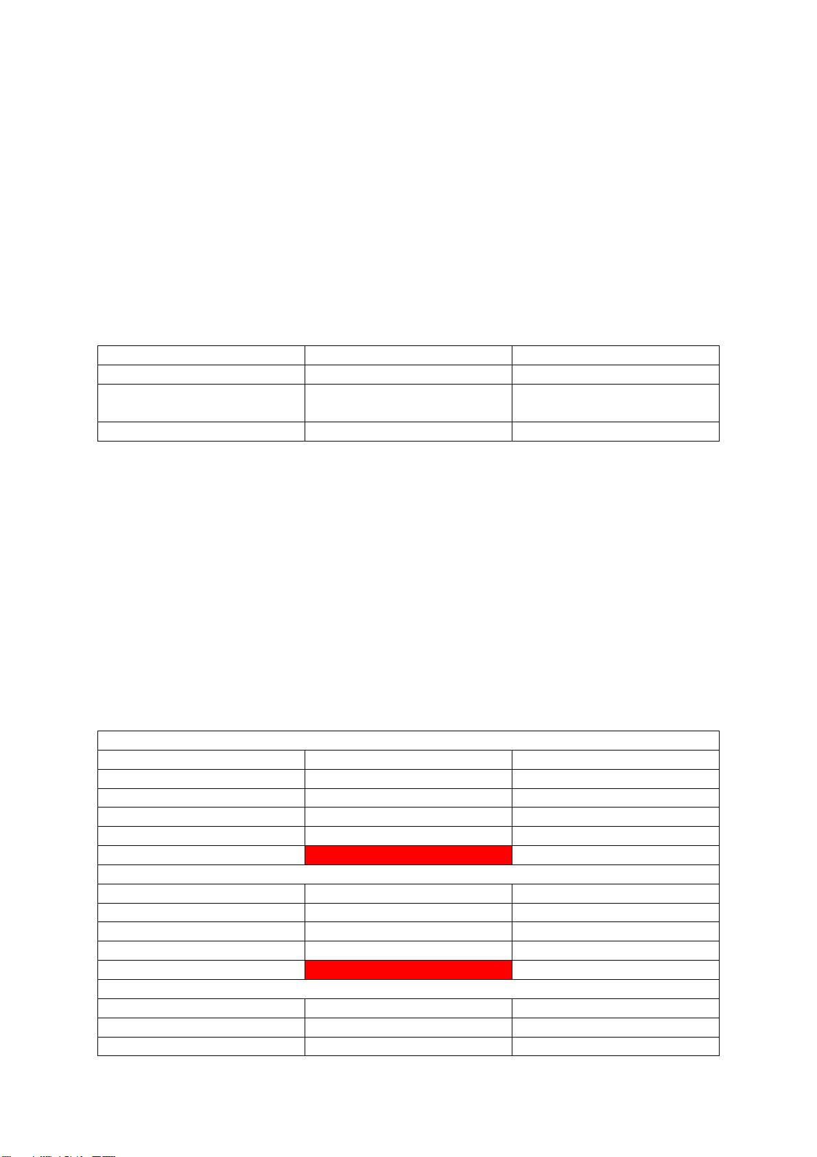
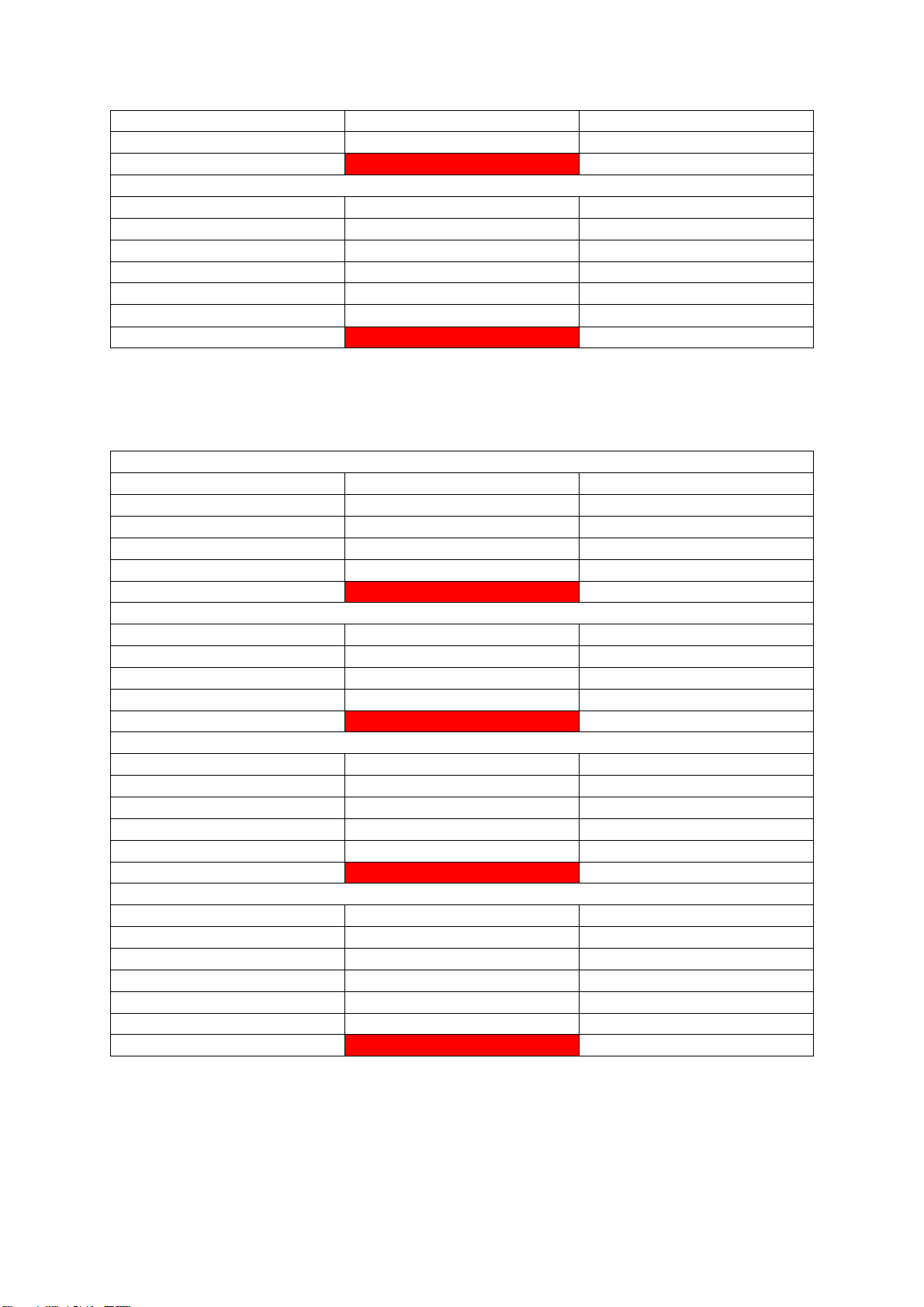
ISKRAEMECO GL Charge GlowBox User manual

Manual GlowBox
GL Charge d.o.o.

Table of Contents
Pre-installation ...................................................................................................................................1
Safety Precautions ..........................................................................................................................2
Technical Specifications ..................................................................................................................3
Site Selection and Preparation ........................................................................................................4
Voltage Drop...............................................................................................................................4
Continuity Test for Earthing Conductor .......................................................................................5
Electrical Installation Requirements ................................................................................................7
Earthing System ..........................................................................................................................7
Electrical Cables ..........................................................................................................................8
Stand ..........................................................................................................................................8
On the Wall...............................................................................................................................10
Examples of Wiring Systems......................................................................................................11
Connections for Multiple Chargers ............................................................................................12
Network....................................................................................................................................14
Energy Meter ............................................................................................................................14
Installation........................................................................................................................................15
Safety Precautions ........................................................................................................................16
Electrical Installation.....................................................................................................................17
Safety pillar installation.................................................................................................................21
DLM Connection ...........................................................................................................................22
Energy Meter Connection..........................................................................................................22
DLM Connection .......................................................................................................................22
1 Phase Installation ...................................................................................................................24
Post Installation Maintenance.......................................................................................................25
General Inspection of the Station ..............................................................................................25
Check the Protection Elements..................................................................................................25
Configuration....................................................................................................................................26
Controller Update .........................................................................................................................27
RFID (Pulse Mode) Western Controller..........................................................................................29
LED Configuration Western Controller...........................................................................................30
Current Setting for Western Controller .........................................................................................31
Service..............................................................................................................................................33
Service..........................................................................................................................................34
Element Replacement ...............................................................................................................34
Troubleshooting........................................................................................................................34

Device Condition Checking............................................................................................................35
Visual Inspection:......................................................................................................................35
Security Element Verification: ...................................................................................................35
Functionality Tests: ...................................................................................................................35
Electrical Measurements Procedure..............................................................................................36
Measurements of the Continuity of Protective Conductors .......................................................36
Measurements of Wire Insulation Resistance............................................................................36
Checking the Operation of Residual Current Devices .................................................................36
Electrical Scheme..........................................................................................................................37

Table of Tables
Table 1: Specs .....................................................................................................................................3
Table 2: Adequate Power Supply.........................................................................................................4
Table 3: Voltage Drop 16A ..................................................................................................................4
Table 4: Voltage Drop 32A ..................................................................................................................5
Table 5: Wiring Systems....................................................................................................................11
Table 6: Cross - Section for Different Installations PVC 16A ...............................................................13
Table 7: Cross - Section for Different Installations XLPE, EPR 16A ......................................................13
Table 8: Cross - Section for Different Installations PVC 32A ...............................................................13
Table 9: Cross - Section for Different Installations XLPE, EPR 32A ......................................................14

Table of Figures
Figure 1: Continuity Measurement......................................................................................................6
Figure 2: TN-C-S System ......................................................................................................................7
Figure 3: TN-S .....................................................................................................................................7
Figure 4: TT.........................................................................................................................................8
Figure 5: Stand....................................................................................................................................9
Figure 6: Anchor .................................................................................................................................9
Figure 7: Anchor Dimensions ............................................................................................................10
Figure 8: Back Plate Dimension .........................................................................................................10
Figure 9: Star Topology .....................................................................................................................12
Figure 10: Daisy Chain Topology........................................................................................................12
Figure 11: DLM UTP Scheme .............................................................................................................14
Figure 12: M6 Screw Removal...........................................................................................................17
Figure 13: Back Plate Mounting.........................................................................................................17
Figure 14: Type 2 Cable Installation...................................................................................................18
Figure 15: Type 2 Cable Connection ..................................................................................................18
Figure 16: Tie Installation..................................................................................................................18
Figure 17: Power Supply Connection.................................................................................................19
Figure 18: Sauro Cable Connections ..................................................................................................19
Figure 19: Safety Pillar ......................................................................................................................21
Figure 20: Energy Meter Installation .................................................................................................22
Figure 21: Energy Meter Connections ...............................................................................................23
Figure 22: DLM Connections .............................................................................................................23
Figure 23: 1 Phase Installation ..........................................................................................................24
Figure 24: EVCC_FW_upgrade tool....................................................................................................27
Figure 25: Controller Update Procedure 1.1 ......................................................................................27
Figure 26: Controller Update Procedure 1.2 ......................................................................................28
Figure 27: Controller Update Procedure 1.3 ......................................................................................28
Figure 28: Pulse Mode ......................................................................................................................29
Figure 29: LED Configuration.............................................................................................................30
Figure 30: Convert from DEC to HEX..................................................................................................31
Figure 31: Set Charging Current ........................................................................................................32

1
PRE-INSTALLATION

2
SAFETY PRECAUTIONS
Electrical Safety: The charging station must be installed by a licensed electrician or certified
installer in accordance with local electrical codes and regulations. Do not attempt to modify
or repair the charging station's electrical components unless you are qualified to do so.
Grounding: Proper grounding is essential for safe operation of the charging station. Ensure
that the charging station is grounded and that all electrical connections are secure.
User Safety: Ensure that the charging station is installed in a safe and accessible location,
away from any potential hazards or obstructions. Users should never touch the charging
station while it is in use and should avoid touching any live electrical components.
Environment: Install the charging station in a location that is protected from the elements
and other environmental factors, such as temperatures above +60°c, moisture, and corrosive
materials. It is advised to maintain a relative humidity of up to 95%, while also avoiding any
condensation buildup.
Ventilation: Provide adequate ventilation around the charging station to prevent overheating
and ensure that the unit is operating within its recommended temperature range.
Authorized Users Only: Restrict access to the charging station to authorized users only.
Ensure that users are trained on the proper use and safety procedures before allowing them
to use the charging station.
Emergency Procedures: In the event of an emergency, follow the manufacturer's
recommended procedures for shutting down and isolating the charging station. Have a plan
in place for addressing any potential emergencies or hazards.
For the installation of charging stations, not equipped with an integrated FID device, it is
strongly recommended the installation of a proper external FID device in the electrical
cabinet.

3
TECHNICAL SPECIFICATIONS
Table 1: Specs
Input voltage
230/400V AC
Input current (for max charging)
32A/16A per phase
Frequency
50/60 Hz
Output Voltage
240V AC
Maximum Output Current
32A/16A per phase
Maximum Output Power
22kW/11kW
Plug Type
Type 2 (IEC 62196-2)
Cable Length
5m (16.4ft)
IP Rating
IP55
Operating temperature
-25°c … +55°c
IK Impact Rating
IK10
Dimensions
300 x 220 x 140
Weight
8kg
Relative Humidity
95%
Case
powder coated steel + tempered glass
The GlowBox is designed to provide fast and reliable charging for your electric vehicle. With a
maximum output power of 22kW/11kW and a maximum output current of 3x32A/16A, it can charge
most electric vehicles in just a few hours.
The charging station is equipped with a Type 2 (IEC 62196-2) plug, which is compatible with most
electric vehicles in Europe. The cable length of 5m (16.4ft) provides plenty of reach for most charging
setups, and the IP55 rating ensures that the charging station is protected from dust and water
splashes.
With its compact dimensions of 300mm x 220mm x 140mm and lightweight design of 8kg (17.6lb),
the GlowBox is easy to install and transport. The charging station also operates in a wide range of
temperatures, making it suitable for use in different climates.
These technical specifications ensure that the GlowBox is a reliable and efficient solution for your
electric vehicle charging needs.

4
SITE SELECTION AND PREPARATION
Location: Choose a location that is easily accessible for electric vehicles (EVs). The charging station
should be located in a dry and well-ventilated area, protected from direct sunlight.
Space: The charging station should be installed in a location that allows for easy access and
maneuvering of EVs.
Power Supply: Verify that the location has adequate power supply to support the charging station.
Consult with a licensed electrician to ensure that the electrical infrastructure can handle the load of
the charging station.
Table 2: Adequate Power Supply
22Kw
11kW
Voltage
230/400V AC
230/400V AC
Current
32A per phase (If less we
recommend DLM)
16A per phase (If less we
recommend DLM)
Cable thickness
6mm2(minimum)
4mm2(minimum)
Mounting: Determine the best mounting option for the charging station based on the site conditions.
The charging station can be mounted to a wall or on a stand.
Voltage Drop
The maximum allowable voltage drop for an installation can vary from country to country. Typically,
the requirement is to keep the voltage drop below 4% (or sometimes below 5%). The length of the
conductors, their material, and the charging current are important factors in determining the
appropriate cross-section of cables. However, it's important to note that voltage drop can also occur
in other components and devices. Therefore, it is advisable to consider some additional reserve when
selecting the cross-section of cables to account for these factors.
Voltage drop for copper and charging current of 16A:
Table 3: Voltage Drop 16A
Cross-section 6mm2 (10AWG)
Length (m)
Single phase, voltage drop %
Three phase, voltage drop%
50
2,38
2,06
60
2,86
2,48
70
3,33
2,89
80
3,81
3,30
90
4,29
3,71
Cross-section 10mm2(8AWG)
90
2,87
2,48
100
3,18
2,76
110
3,50
3,03
120
3,82
3,31
130
4,14
3,58
Cross-section 16mm2(6AWG)
150
3,09
2,67
160
3,29
2,85
170
3,50
3,03

5
180
3,70
3,21
190
3,91
3,39
200
4,12
3,56
Cross-section 25mm2(4AWG)
240
3,24
2,81
250
3,38
2,92
260
3,51
3,04
270
3,65
3,16
280
3,78
3,28
290
3,92
3,39
300
4,05
3,51
Voltage drop for copper and charging current of 32A:
Table 4: Voltage Drop 32A
Cross-section 6mm2 (10AWG)
Length (m)
Single phase, voltage drop %
Three phase, voltage drop%
10
0,95
0,83
20
1,91
1,65
30
2,86
2,48
40
3,81
3,30
50
4,76
4,13
Cross-section 10mm2(8AWG)
30
1,91
1,65
40
2,55
2,21
50
3,18
2,76
60
3,82
3,31
70
4,46
3,86
Cross-section 16mm2(6AWG)
50
2,06
1,78
60
2,47
2,14
70
2,88
2,50
80
3,29
2,85
90
3,70
3,21
100
4,12
3,56
Cross-section 25mm2(4AWG)
90
2,43
2,11
100
2,70
2,34
110
2,97
2,57
120
3,24
2,81
130
3,51
3,04
140
3,78
3,28
150
4,05
3,51
Continuity Test for Earthing Conductor
To ensure proper safety measures, it is important to perform a continuity measurement on the
protective conductors, including those in the main and additional equipotential. This measurement
involves checking the connection between the PE terminal of the charging station's socket and the

6
inlet PE conductor. If the charging station is equipped with a cable, the measurement should be
made between the PE conductor of the cable plug and the inlet PE conductor.
Before conducting these measurements, it is crucial to switch off the charging station or the main
power supply to eliminate any potential hazards.
For accurate results, the continuity measurement should be performed with a current equal to or
greater than 200 mA. The open circuit test voltage should range between 4 and 24V, whether AC or
DC. The measuring range should cover values from 0.2 Ω to 2 Ω, with a maximum permissible
operating uncertainty of +- 30%. Digital equipment used for measurement should have a resolution
of at least 0.1 Ω.
Using an instrument with the capability to measure at higher currents than 200 mA can enhance the
accuracy of the measurement. The figure below illustrates the method of conducting the continuity
measurement.
Figure 1: Continuity Measurement
To meet the continuity requirement, the connection resistance should not exceed 2 Ω.

7
ELECTRICAL INSTALLATION REQUIREMENTS
Earthing System
The earthing system in an electrical installation serves a crucial role in ensuring electrical safety and
protecting against potential hazards. It primarily focuses on mitigating risks associated with static
buildup and safeguarding against power surges induced by lightning strikes or switching events.
GlowBox is designed to be compatible with multiple earthing systems, including TN-C-S, TN-S, and TT.
These systems provide reliable grounding solutions that are widely adopted and recognized for their
effectiveness in maintaining a safe electrical environment. By supporting these earthing systems,
GlowBox ensures enhanced safety and compatibility for a variety of installation scenarios.
Figure 2: TN-C-S System
Figure 3: TN-S

8
Figure 4: TT
Electrical Cables
Power Supply: The electrical infrastructure must be able to support the charging station's
power output.
Cable Requirements: The charging station requires a 5-wire, 3-phase, neutral wire and
ground cable. The cable must have a minimum size of 6 mm2(10 AWG) for 32A and 4 mm2
(12AWG) for 16A.
Grounding: Proper grounding is essential for safe operation of the charging station. Ensure
that the charging station is properly grounded and that all electrical connections are secure.
Protection devices: The charging station must be protected by a properly rated circuit
breaker and FID device. Both should be installed in the electrical cabinet before the charger.
Electrical Safety: The charging station must be installed by a licensed electrician or certified
installer in accordance with local electrical codes and regulations. Do not attempt to modify
or repair the charging station's electrical components unless you are qualified to do so.
Stand
To prepare for the installation for the charger on a stand, follow the steps below:
1. The charger comes with a backplate that has four holes. Which mount on the stand.
2. The stand should have four screws spot welded to it, which align with the holes on the
backplate.
3. To install the stand on the ground, we recommend using an anchor. The anchor comes with
four screws that need to be concreted into the ground. The stand then mounts on the four
screws on the anchor. For pre installation it’s important to prepare the spot for the charger.
If you are using an anchor, prepare the hole and pour concrete to secure the anchor into the
ground. Allow enough space for the cables to pass through the concrete and anchor.. Make
sure to leave approximately 1 meter of space around the anchor to allow for installation and
maintenance purposes.
4. Ensure that the anchor is installed on a solid and stable surface, and that it is securely fixed
to the ground.
5. Make sure that the anchor is leveled so the stand can have a leveled surface.
6. Cables come from the ground trough the stand and hole in the back plate where the cable
gland is mounted.

9
Figure 5: Stand
Figure 6: Anchor

10
Figure 7: Anchor Dimensions
On the Wall
To prepare for the installation for the charger on a wall, follow the steps below:
1. The charger comes with a backplate that has four holes, which mount on the wall.
2. Four holes should be drilled on the wall in same spot as on the back plate.
3. Prepare the holes in advanced to ensure an easy installation (figure 3).
4. Cables come from the back plate where the cable gland is mounted, so make sure there is
room for cables behind the back plate.
Figure 8: Back Plate Dimension

11
Examples of Wiring Systems
Table 5: Wiring Systems
Methods of installation
Description
Reference method
of installation to
be used to obtain
current-carrying
capacity
Insulated conductors or single-core cables in
conduit in a thermally insulated wall
A1
Multi-core cables in conduit in a thermally
insulated wall
A2
Insulated conductors or single-core cables in
conduit on a wooden, or masonry wall or spaced
less than 0,3 x conduit diameter from it
B1
Multi-core cable in conduit on a wooden, or
masonry wall or spaced less than 0,3 x conduit
diameter from it
B2
Single-core or multi-core cables: - fixed on, or
spaced less than 0.3 x cable diameter from a
wooden wall
C
Single-core or multi-core cables:
On unperforated tray run horizontally or vertically
C
Single-core or multi-core cables:
On perforated tray run horizontally or vertically
E or F

12
Bare or insulated conductors on insulators
G
Multi-core cables in conduit or in cable ducting in
the ground
D1
Single-core cable in conduit or in cable ducting in
the ground
D1
Connections for Multiple Chargers
Figure 9: Star Topology
Figure 10: Daisy Chain Topology
Please be aware that the cable cross sections mentioned in the manual are approximate values
calculated primarily based on current requirements. However, it is essential to consider additional
factors when selecting the appropriate cable cross section for a particular application.

13
It is highly recommended to consult with a qualified electrician or engineer who can assess the
specific requirements and conditions of the installation. They will be able to provide accurate
calculations and recommendations for the appropriate cable cross section, considering all relevant
factors to ensure the safety and reliability of the electrical system.
PVC insulation, copper conductors 16A:
Table 6: Cross - Section for Different Installations PVC 16A
Number of chargers
A1
A2
B1
B2
C
D1
D2
1 (16A)
2,5
2,5
2,5
2,5
1,5
1,5
1,5
2 (32A)
10
10
6
6
4
6
4
3 (48A)
16
16
10
16
10
10
10
4 (64A)
25
25
16
25
16
16
16
5 (80A)
35
35
25
25
25
25
25
6 (96A)
50
50
35
35
25
35
35
7 (112A)
70
70
50
50
35
50
50
8 (128A)
70
95
50
70
50
70
50
9 (144A)
95
95
70
70
50
95
70
10 (160A)
95
120
70
95
70
95
70
XLPE or EPR insulation, copper conductors 16A:
Table 7: Cross - Section for Different Installations XLPE, EPR 16A
Number of chargers
A1
A2
B1
B2
C
D1
D2
1 (16A)
1,5
1,5
1,5
1,5
1,5
1,5
1,5
2 (32A)
6
6
4
4
10
4
4
3 (48A)
10
10
6
10
16
10
6
4 (64A)
16
16
10
16
25
16
10
5 (80A)
25
25
16
16
35
25
16
6 (96A)
35
35
25
25
50
25
25
7 (112A)
35
50
25
35
70
35
35
8 (128A)
50
50
35
35
70
50
35
9 (144A)
70
70
35
50
95
70
50
10 (160A)
70
70
50
70
95
70
70
PVC insulation, copper conductors 32A:
Table 8: Cross - Section for Different Installations PVC 32A
Number of chargers
A1
A2
B1
B2
C
D1
D2
1 (32A)
6
6
4
6
4
4
4
2 (64A)
25
25
16
25
16
16
16
3 (96A)
50
50
35
35
25
35
35
4 (128A)
70
95
50
70
50
70
50
5 (160A)
95
120
70
95
70
95
70
6 (192A)
150
150
95
120
95
120
95
7 (224A)
185
240
120
150
120
185
150
8 (256A)
240
240
185
240
120
240
185
9 (288A)
300
300
185
240
150
300
240
10 (320A)
300
x
240
300
185
x
240

14
XLPE or EPR insulation, copper conductors 32A:
Table 9: Cross - Section for Different Installations XLPE, EPR 32A
Number of chargers
A1
A2
B1
B2
C
D1
D2
1 (32A)
6
6
4
4
4
4
4
2 (64A)
16
16
10
16
10
16
10
3 (96A)
35
35
25
25
16
25
25
4 (128A)
50
50
35
35
35
50
35
5 (160A)
70
70
50
70
50
70
70
6 (192A)
95
95
70
70
70
95
95
7 (224A)
120
120
95
120
70
150
95
8 (256A)
150
150
95
120
95
185
120
9 (288A)
185
185
120
150
120
240
185
10 (320A)
185
240
150
185
120
240
185
Network
To establish a connection for the DLM system, you will need to prepare a UTP cable that will be wired
from the energy meter to the charger. The energy meter is mounted before every consumer in the
house, except for the charger itself. It is located in the electrical cabinet. If there is not enough space
in the existing electrical cabinet, an additional electrical cabinet can be installed. Ensure that the UTP
cable is properly prepared and runs from the energy meter to the charger to enable the necessary
network communication.
Figure 11: DLM UTP Scheme
Energy Meter
To prepare for energy meter, you will need to ensure that there is enough space in your electrical
cabinet. If space is limited, an additional electrical cabinet can be installed. The energy meter should
be mounted in a way that allows for the three phases to run through it. Additionally, you will need to
connect a neutral wire to the energy meter. Please note that the energy meter should be mounted
before all consumers on the house except the charger itself.

15
INSTALLATION
Table of contents
Other ISKRAEMECO Batteries Charger manuals