ISKRAEMECO GL Charge User manual

Manual PublicBox
GL Charge d.o.o.

Table of Contents
Pre-installation ...................................................................................................................................1
Safety Precautions ..........................................................................................................................2
Technical Specifications ..................................................................................................................3
Site Selection and Preparation ........................................................................................................4
Voltage Drop...............................................................................................................................4
Continuity Test for Earthing Conductor .......................................................................................5
Electrical Installation Requirements ................................................................................................7
Earthing System ..........................................................................................................................7
Electrical Cables ..........................................................................................................................8
Mounting with Anchor ................................................................................................................8
Examples of Wiring Systems........................................................................................................9
Cable Connections for Multiple Chargers...................................................................................11
Network....................................................................................................................................12
DHCP or Static IP .......................................................................................................................12
Load Management ....................................................................................................................13
Installation........................................................................................................................................15
Safety Precautions ........................................................................................................................16
Electrical Installation.....................................................................................................................17
Safety pillar installation.................................................................................................................19
Network and Communication Installation .....................................................................................20
Load Management Connection .....................................................................................................21
Energy Meter Connection..........................................................................................................21
Load Management Connection .................................................................................................21
Post Installation Maintenance.......................................................................................................22
General Inspection of the Station ..............................................................................................22
Check the Protection Elements..................................................................................................22
Configuration....................................................................................................................................23
Charging Station Web Interface.....................................................................................................24
Connect to Web Interface .........................................................................................................24
Password ..................................................................................................................................28
Network Configuration..................................................................................................................30
Setting Up Charging Configurations...............................................................................................32
Other Configuration Option ..........................................................................................................35
Load Management ....................................................................................................................35
RFID ..........................................................................................................................................37

OCPP.........................................................................................................................................38
4g .................................................................................................................................................41
Service..............................................................................................................................................43
Service..........................................................................................................................................44
Element Replacement ...............................................................................................................44
Troubleshooting........................................................................................................................44
Device Condition Checking............................................................................................................45
Visual Inspection:......................................................................................................................45
Security Element Verification: ...................................................................................................45
Functionality Tests: ...................................................................................................................45
Electrical Measurements Procedure..............................................................................................46
Measurements of the Continuity of Protective Conductors .......................................................46
Measurements of Wire Insulation Resistance............................................................................46
Checking the Operation of Residual Current Devices .................................................................46
Electrical Scheme..........................................................................................................................47

Table of Tables
Table 1: Specs .....................................................................................................................................3
Table 2: Adequate Power Supply.........................................................................................................4
Table 3: Voltage Drop .........................................................................................................................4
Table 4: Wiring Systems......................................................................................................................9
Table 5: Cross - Section for Different Installations PVC ......................................................................11
Table 6: Cross - Section for Different Installations XLPE, EPR .............................................................12
Table 7: Password for Web Interface.................................................................................................28

Table of Figures
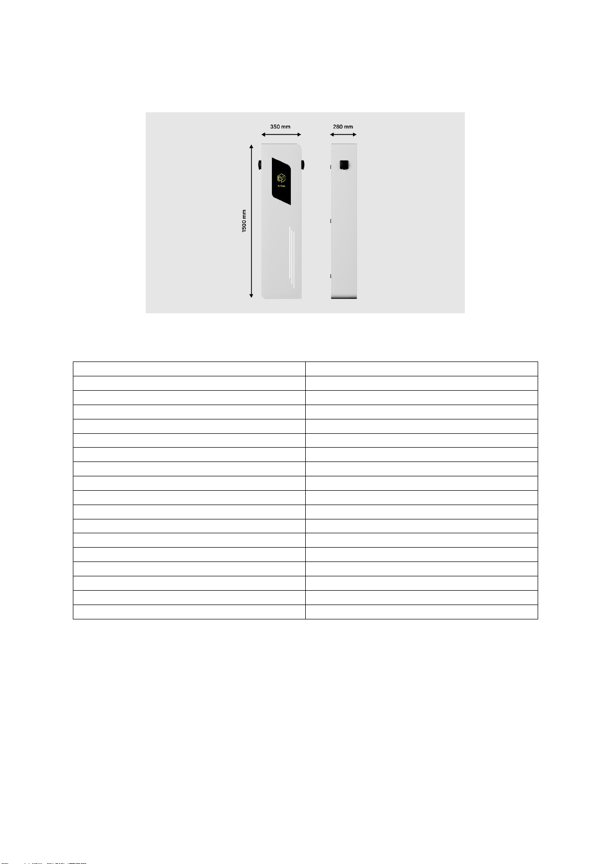
Figure 1: Dimensions...........................................................................................................................3
Figure 2: Continuity Measurement......................................................................................................6
Figure 3: TN-C-S System ......................................................................................................................7
Figure 4: TN-S .....................................................................................................................................7
Figure 5: TT.........................................................................................................................................8
Figure 6: Anchor .................................................................................................................................9
Figure 7: Star Topology .....................................................................................................................11
Figure 8: Daisy Chain Topology..........................................................................................................11
Figure 9: Daisy Chaining....................................................................................................................13
Figure 10: PublicBox Installation on Anchor ......................................................................................17
Figure 11: Power Supply and Communication ...................................................................................17
Figure 12: Position of Bolts ...............................................................................................................18
Figure 13: Safety Pillar ......................................................................................................................19
Figure 14: Ethernet Cable Connection...............................................................................................20
Figure 15: Energy Meter Connection.................................................................................................21
Figure 16: IP Scanner ........................................................................................................................24
Figure 17: Searching for Command Prompt.......................................................................................25
Figure 18: Open Command Prompt...................................................................................................25
Figure 19: Pinging the IP ...................................................................................................................25
Figure 20: Driver Download Page ......................................................................................................26
Figure 21: Driver Folder Creation ......................................................................................................27
Figure 22: Controller USB-C Connection............................................................................................27
Figure 23: Device Manager ...............................................................................................................28
Figure 24: Update Driver...................................................................................................................28
Figure 25: Static IP Settings...............................................................................................................30
Figure 26: Dynamic IP Settings ..........................................................................................................31
Figure 27: Charging Park ...................................................................................................................32
Figure 28: Name and Location...........................................................................................................32
Figure 29: Connection Type...............................................................................................................33
Figure 30: Charge Current.................................................................................................................33
Figure 31: Energy Meter....................................................................................................................33
Figure 32: Contactor Monitoring.......................................................................................................33
Figure 33: Charging Release ..............................................................................................................34
Figure 34: Check Load Management Port..........................................................................................35
Figure 35: Load Management Configuration .....................................................................................36
Figure 36: Load Management Configuration 2...................................................................................36
Figure 37: Load Management Refresh...............................................................................................37
Figure 38: Release Mode "By Local whitelist"....................................................................................37
Figure 39: Whitelist "New Entry".......................................................................................................38
Figure 40: OCPP Configuration 1.1 ....................................................................................................38
Figure 41: OCPP Configuration 1.2 ....................................................................................................39
Figure 42: OCPP Configuration 1.3 ....................................................................................................39
Figure 43: OCPP Status......................................................................................................................40
Figure 44: OCPP Cellular Connection.................................................................................................41
Figure 45: Modem Configuration ......................................................................................................41
Figure 46: Modem Connection Status ...............................................................................................42

1
PRE-INSTALLATION

2
SAFETY PRECAUTIONS
Electrical Safety: The charging station must be installed by a licensed electrician or certified
installer in accordance with local electrical codes and regulations. Do not attempt to modify
or repair the charging station's electrical components unless you are qualified to do so.
Grounding: Proper grounding is essential for safe operation of the charging station. Ensure
that the charging station is grounded and that all electrical connections are secure.
User Safety: Ensure that the charging station is installed in a safe and accessible location,
away from any potential hazards or obstructions. Users should never touch the charging
station while it is in use and should avoid touching any live electrical components.
Environment: Install the charging station in a location that is protected from the elements
and other environmental factors, such as temperatures above +60°c, moisture, and corrosive
materials. It is advised to maintain a relative humidity of up to 95%, while also avoiding any
condensation buildup.
Ventilation: Provide adequate ventilation around the charging station to prevent overheating
and ensure that the unit is operating within its recommended temperature range.
Authorized Users Only: Restrict access to the charging station to authorized users only.
Ensure that users are trained on the proper use and safety procedures before allowing them
to use the charging station.
Emergency Procedures: In the event of an emergency, follow the manufacturer's
recommended procedures for shutting down and isolating the charging station. Have a plan
in place for addressing any potential emergencies or hazards.
For the installation of charging stations, not equipped with an integrated FID device, it is
strongly recommended the installation of a proper external FID device in the electrical
cabinet.

3
TECHNICAL SPECIFICATIONS
Figure 1: Dimensions
Table 1: Specs
Input voltage
230/400V AC
Input current (for max charging)
64A per phase
Frequency
50/60 Hz
Output Voltage
240V AC
Maximum Output Current (1 socket)
32A per phase
Maximum Output Power (1 socket)
22kW
Maximum station power consumption
44kW
Plug Type
Type 2 (IEC 62196-2)
IP Rating
IP55
Operating temperature
-25°c … +55°c
IK Impact Rating
IK10
Dimensions
1500 x 350 x 280
Weight
57kg
Relative Humidity
95%
Case
powder coated steel + tempered glass
Communication interfaces
Ethernet; 4G
Communication protocol
OCPP 1.6
Support for RFID cards in standards
SO14443, ISO18092 (NFC) and MIFARE
The PublicBox is designed to provide fast and reliable charging for your electric vehicle. With a
maximum output power of 2x22kW and a maximum output current of 3x64A, it can charge most
electric vehicles in just a few hours.
The charging station is equipped with two Type 2 (IEC 62196-2) socket, which are compatible with
most electric vehicles in Europe. The IP55 rating ensures that the charging station is protected from
dust and water splashes.
The charging station also operates in a wide range of temperatures, making it suitable for use in
different climates.

4
SITE SELECTION AND PREPARATION
Location: Choose a location that is easily accessible for electric vehicles (EVs). The charging station
should be located in a dry and well-ventilated area, protected from direct sunlight.
Space: Ensure that there is enough space for the charging station and any necessary signage or
markings. The charging station should be installed in a location that allows for easy access and
maneuvering of EVs.
Power Supply: Verify that the location has adequate power supply to support the charging station.
Consult with a licensed electrician to ensure that the electrical infrastructure can handle the load of
the charging station.
Table 2: Adequate Power Supply
2x22Kw
Voltage
230/400V AC
Current
64A per phase (If less we
recommend DLM)
Cable thickness
16mm2 (minimum)
Permits: Check with local authorities to determine if any permits or approvals are required for
installation of the charging station.
Mounting: Determine the best mounting option for the charging station based on the site conditions.
The charging station can be mounted to a wall or on a stand.
Signage: Install appropriate signage to identify the charging station and provide instructions for use.
Accessibility: Ensure that the charging station is accessible to all users, including those with
disabilities. The installation should comply with local accessibility regulations.
Voltage Drop
The maximum allowable voltage drop for an installation can vary from country to country. Typically,
the requirement is to keep the voltage drop below 4% (or sometimes below 5%). The length of the
conductors, their material, and the charging current are important factors in determining the
appropriate cross-section of cables. However, it's important to note that voltage drop can also occur
in other components and devices. Therefore, it is advisable to consider some additional reserve when
selecting the cross-section of cables to account for these factors.
Voltage drop for copper and charging current of 64A:
Table 3: Voltage Drop
Cross-section 10mm2 (8AWG)
Length (m)
Single phase, voltage drop %
Three phase, voltage drop%
10
1,27
1,1
20
2,55
2,21
30
3,82
3,31
40
5,09
4,41
Cross-section 16mm2(6AWG)
10
0,82
0,71
20
1,65
1,43

5
30
2,47
2,14
40
3,29
2,85
50
4,12
3,56
Cross-section 25mm2(4AWG)
30
1,26
1,40
40
2,16
1,87
50
2,70
2,34
60
3,24
2,81
70
3,78
3,28
80
4,32
3,74
Cross-section 35mm2(2AWG)
50
1,84
1,59
60
2,20
1,91
70
2,57
2,22
80
2,94
2,54
90
3,30
2,86
100
3,67
1,18
110
4,04
3,50
Continuity Test for Earthing Conductor
To ensure proper safety measures, it is important to perform a continuity measurement on the
protective conductors, including those in the main and additional equipotential. This measurement
involves checking the connection between the PE terminal of the charging station's socket and the
inlet PE conductor. If the charging station is equipped with a cable, the measurement should be
made between the PE conductor of the cable plug and the inlet PE conductor.
Before conducting these measurements, it is crucial to switch off the charging station or the main
power supply to eliminate any potential hazards.
For accurate results, the continuity measurement should be performed with a current equal to or
greater than 200 mA. The open circuit test voltage should range between 4 and 24V, whether AC or
DC. The measuring range should cover values from 0.2 Ω to 2 Ω, with a maximum permissible
operating uncertainty of +- 30%. Digital equipment used for measurement should have a resolution
of at least 0.1 Ω.
Using an instrument with the capability to measure at higher currents than 200 mA can enhance the
accuracy of the measurement. The figure below illustrates the method of conducting the continuity
measurement.

6
Figure 2: Continuity Measurement
To meet the continuity requirement, the connection resistance should not exceed 2 Ω.

7
ELECTRICAL INSTALLATION REQUIREMENTS
Earthing System
The earthing system in an electrical installation serves a crucial role in ensuring electrical safety and
protecting against potential hazards. It primarily focuses on mitigating risks associated with static
buildup and safeguarding against power surges induced by lightning strikes or switching events.
PublicBox is designed to be compatible with multiple earthing systems, including TN-C-S, TN-S, and
TT. These systems provide reliable grounding solutions that are widely adopted and recognized for
their effectiveness in maintaining a safe electrical environment. By supporting these earthing
systems, PublicBox ensures enhanced safety and compatibility for a variety of installation scenarios.
Figure 3: TN-C-S System
Figure 4: TN-S

8
Figure 5: TT
Electrical Cables
Power Supply: The electrical infrastructure must be able to support the charging station's
power output.
Cable Requirements: The charging station requires a 5-wire, 3-phase, neutral wire + ground
cable. The cable must have a minimum size of 16 mm2(6 AWG) and be capable of handling a
maximum continuous current of 64A. And communication ETH cable (2 x ETH cable, directly
from the switch or 1 x ETH cable, which is connected with a Y splitter on the switch side and
split with a Y splitter on the side of the charging station).
Grounding: Proper grounding is essential for the safe operation of the charging station.
Ensure that the charging station is properly grounded and that all electrical connections are
secure.
Circuit Breaker: The charging station must be protected by a properly rated circuit breaker.
The circuit breaker should be installed in accordance with local electrical codes and
regulations.
Electrical Safety: The charging station must be installed by a licensed electrician or certified
installer in accordance with local electrical codes and regulations. Do not attempt to modify
or repair the charging station's electrical components unless you are qualified to do so.
Mounting with Anchor
To prepare for the installation of the charger, follow the steps below:
1. To install the PublicBox on the ground, we recommend using an anchor. The anchor needs to
be concreted into the ground. PublicBox then mounts the four screws on the anchor. For pre-
installation it’s important to prepare the spot for the charger. If you are using an anchor,
prepare the hole and pour concrete to secure the anchor into the ground. Allow enough
space for the cables to pass through the concrete and anchor. Make sure to leave
approximately 1 meter of space around the anchor to allow for installation and maintenance
purposes.
2. Ensure that the anchor is installed on a solid and stable surface, and that it is securely fixed
to the ground.
3. Make sure that the anchor is leveled so the PublicBox has a leveled surface.
4. Cables come from the ground through the hole on the bottom of the PublicBox.

9
Figure 6: Anchor
Examples of Wiring Systems
Table 4: Wiring Systems
Methods of installation
Description
Reference method
of installation to
be used to obtain
current-carrying
capacity
Insulated conductors or single-core cables in
conduit in a thermally insulated wall
A1
Multi-core cables in conduit in a thermally
insulated wall
A2
Insulated conductors or single-core cables in
conduit on a wooden, or masonry wall or spaced
less than 0,3 x conduit diameter from it
B1
Multi-core cable in conduit on a wooden, or
masonry wall or spaced less than 0,3 x conduit
diameter from it
B2
Single-core or multi-core cables: - fixed on, or
spaced less than 0.3 x cable diameter from a
wooden wall
C

10
Single-core or multi-core cables:
On unperforated tray run horizontally or vertically
C
Single-core or multi-core cables:
On perforated tray run horizontally or vertically
E or F
Bare or insulated conductors on insulators
G
Multi-core cables in conduit or in cable ducting in
the ground
D1
Single-core cable in conduit or in cable ducting in
the ground
D1

11
Cable Connections for Multiple Chargers
Figure 7: Star Topology
Figure 8: Daisy Chain Topology
Please be aware that the cable cross sections mentioned in the manual are approximate values
calculated primarily based on current requirements. However, it is essential to consider additional
factors when selecting the appropriate cable cross section for a particular application.
It is highly recommended to consult with a qualified electrician or engineer who can assess the
specific requirements and conditions of the installation. They will be able to provide accurate
calculations and recommendations for the appropriate cable cross section, considering all relevant
factors to ensure the safety and reliability of the electrical system.
PVC insulation, copper conductors:
Table 5: Cross - Section for Different Installations PVC
Number of chargers
A1
A2
B1
B2
C
D1
D2
1 (64A)
25
25
16
25
16
16
16
2 (128A)
70
95
50
70
50
70
50
3 (192A)
150
150
95
120
95
120
95
4 (256A)
240
240
150
240
120
240
185
5 (320A)
300
x
240
300
185
x
300
6 (384A)
x
x
300
x
240
x
x

12
7 (448A)
x
x
x
x
300
x
x
8 (512A)
x
x
x
x
x
x
x
9 (576A)
x
x
x
x
x
x
x
10 (640A)
x
x
x
x
x
x
x
XLPE or EPR insulation, copper conductors:
Table 6: Cross - Section for Different Installations XLPE, EPR
Number of chargers
A1
A2
B1
B2
C
D1
D2
1 (64A)
16
16
10
16
10
16
10
2 (128A)
50
50
35
35
35
50
35
3 (192A)
95
95
70
70
70
95
95
4 (256A)
150
150
95
120
95
185
120
5 (320A)
185
240
150
185
120
240
185
6 (384A)
300
300
185
240
150
x
300
7 (448A)
x
x
240
300
240
x
x
8 (512A)
x
x
300
x
300
x
x
9 (576A)
x
x
x
x
300
x
x
10 (640A)
x
x
x
x
x
x
x
Network
For the PublicBox Platinum to be connected to a network, you will need to prepare an Ethernet
cable. The Ethernet cable should be of sufficient length to reach the desired location of the charging
station and should be properly rated for outdoor use if the charging station will be installed
outdoors. It is recommended to use a shielded Ethernet cable to minimize the risk of interference.
When running the Ethernet cable, care should be taken to avoid sharp bends or kinks, as this can
cause damage to the cable and affect the network connection. Additionally, the Ethernet cable
should be kept away from sources of electromagnetic interference, such as power cables or electrical
equipment, to ensure a stable network connection.
Overall, it is important to ensure that the Ethernet cable used for network connection meets the
necessary requirements for length, rating, and shielding, and that it is installed properly to ensure
reliable network connectivity for the charging station.
DHCP or Static IP
By default, the PublicBox Platinum is set to use DHCP for obtaining an IP address from the network.
However, if the customer wishes to use a static IP address for the charging station, they should
prepare a working IP address in advance. This will allow for a quick and smooth installation process.
When configuring a static IP address for the charging station, it is important to ensure that the IP
address, subnet mask, default gateway, and DNS server settings are set correctly. The customer
should obtain these network settings from their network administrator or Internet Service Provider
(ISP) to ensure that the charging station is properly configured and can communicate with other
devices on the network.
Once the static IP address has been obtained and the network settings have been configured, the
customer can easily set the charging station to use the static IP address during installation. This can
be done through the charging station's configuration menu or via a web browser interface (check
configuration manual).

13
Load Management
For DLM to work you will need internet connection to charger and Energy Meter.
To enable Dynamic Load Management (DLM) functionality on your charging stations, they must be
daisy-chained together using an Ethernet cable. This allows them to communicate with each other
and share information about the available power supply, which enables them to adjust their charging
rates accordingly to prevent overloading the electrical infrastructure.
Daisy-chaining is a method of connecting multiple charging stations in a series using a single Ethernet
cable. In this configuration, the first charging station is connected to the Ethernet switch or router via
the ETH0 port, and then the cable runs from the ETH1 port of the first charging station to the ETH0
port of the next charging station, and so on.
Figure 9: Daisy Chaining
When planning the installation of multiple charging stations, it is important to consider the space
required for the Ethernet cable that will be used for daisy-chaining, the cable will run between the
chargers. The length of the Ethernet cable required will depend on the number of charging stations
connected to and the distance between them. For outdoor installations, it is recommended to use a
shielded Ethernet cable and to avoid sharp bends or kinks when running the cable to prevent
damage.
For Energy Meter connection you need:
oEthernet connection: Energy meter must be connected to the ethernet cable, the
communication between charger and meter takes place via IP address. So it’s important to
prepare an ethernet cable to the energy meter device. Once the charging stations are
properly daisy-chained and connected to the energy meter via IP, the DLM system can be
configured and activated to allow for optimal charging rates and efficient use of the available
power supply. We recommend consulting with a qualified electrician or installer to ensure

14
that the installation is done safely and in compliance with local electrical codes and
regulations.
oPower: To prepare for energy meter, you will need to ensure that there is adequate space in
your electrical cabinet. If space is limited, an additional electrical cabinet can be installed.
The energy meter should be mounted in a way that allows for the three phases to run
through it. Additionally, you will need to connect a neutral wire to the energy meter. Please
note that the energy meter should be mounted before all other consumers.
Other manuals for GL Charge
1
Table of contents
Other ISKRAEMECO Batteries Charger manuals
Popular Batteries Charger manuals by other brands

Analytic Systems
Analytic Systems BCA150 Installation & operation manual

Anthro
Anthro Yes owner's manual

NXP Semiconductors
NXP Semiconductors WCT1011A user guide

SBS
SBS AT10.1 SERIES Operating and service instructions

Twelve South
Twelve South PowerPic mod owner's guide

Eaton
Eaton Green Motion DC 22 user manual

Eyra
Eyra AP–180 Instructions for use

Porter-Cable
Porter-Cable 885942-699 instruction manual

DeWalt
DeWalt XR DCB115 Original instructions

WeTech
WeTech WTC649 user manual

ULTIMATE SPEED
ULTIMATE SPEED USML 3.7 A1 Operation and safety notes translation of the original instructions

LEGRAND
LEGRAND 0 590 00 manual