6
external Level 2 Pipelined Burst Fast Write-Back Cache, 64 bit Burst Bus DRAM and enhanced
IDE with 2 channels and plug and play Ultra I/O, this EIDE Motherboard brings exceptional
processing power that could only be achieved by Mini-computer. Incorporating the new emerging
industrial standard Peripheral Component interconnect (PCI) Local Bus together with the standard
16-bit Industrial Standard Architecture (ISA), this motherboard dramatically boots system I/O
through for even the most demanding application in today’s market.
n
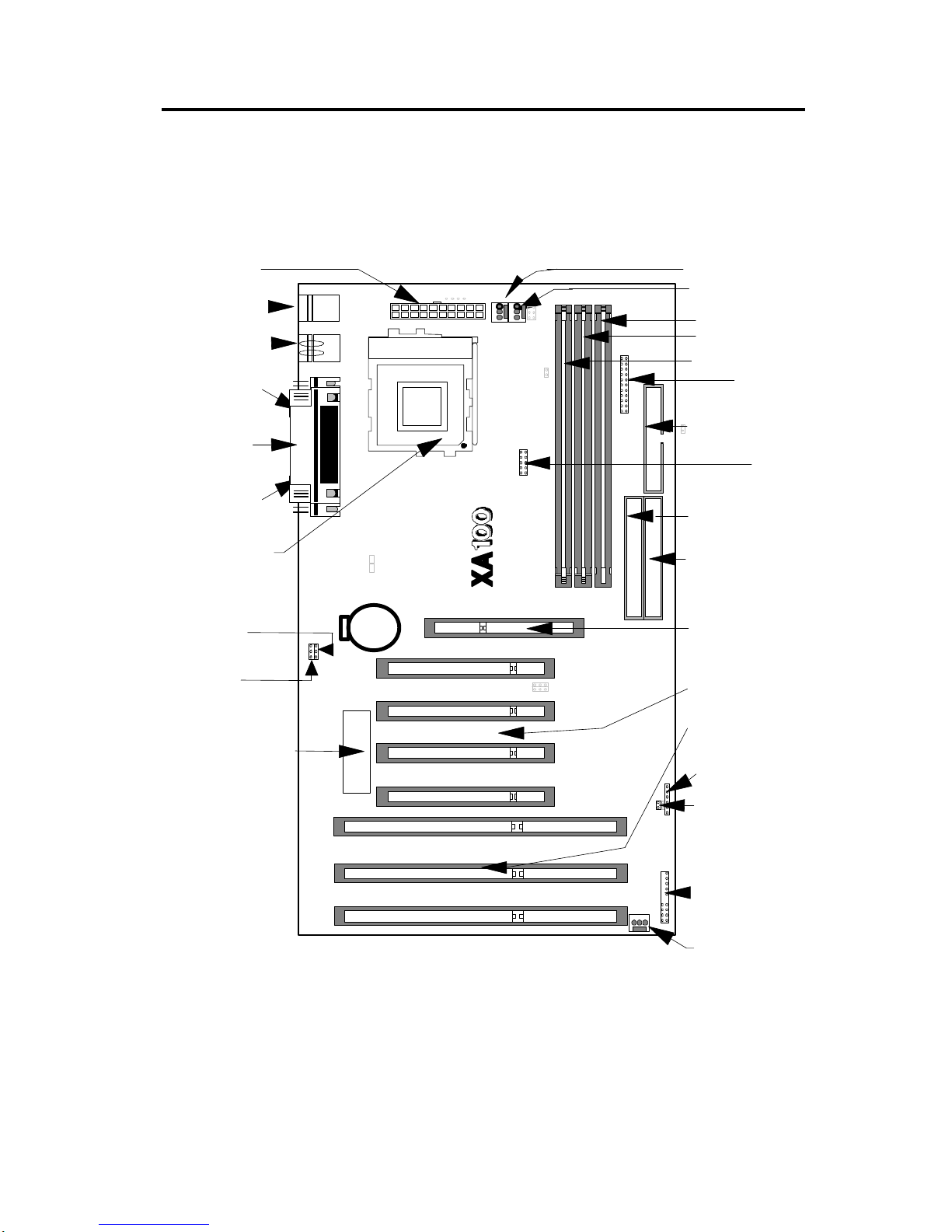
CPU:
CPU socket (socket 7) supports the flexibility of different types of current Cyrix (M1, M2), AMD
(K5, K6) and Intel Pentium, Pentium with MMX processor. Please follow the installation steps
introduced either in Chapter 1 or Chapter 2 to set the CPU frequency.
n
CHIPSET:
ALI Aladdin V PCIset with I/O subsystem chipset is used on this motherboard.
n
BIOS:
AMI BIOS, on-screen "Plug & Play" setup for Enhanced IDE, and Ultra Multi-IO. Support Flash
ROM ( This ROM provides better upgrade ability for users to update their BIOS data on the system
board, users can down-load/ update newer version BIOS from Internet or diskette file.
n
Cache memories:
High performance write-back second Level external static RAM cache. This supports 512KB
Synchronous Pipelined Burst Cache on-baord. The cacheabe size can achieve up to 512 MB. It
also supports 32 bit power-on function, that is, one DIMM will be able to power on the PC.
n
Memories:
3 X 168-pin DIMM (Dual In Line Memory Module) (Rev 1.1)
Support system memory up to 512MB (minimum of 8MB ) on board with either fast page mode,
EDO or the new Synchronous DRAM with DIMM socket (3.3V un-buffered type).
Support 32 bit power-on function. For example, one DIMM is able to power on the computer.
n
AGP (Accelerated Graphic Port) slot:
1 X 124-pin expansion slot, which provides high performance bus for graphics devices and is
designed primarily for 3D applications.
n
Expansion slots:
This motherboard provides :
3 X 16-bits ISA slots, 4 X 32-bits PCI slots
n
Switching DC/DC Voltage Regulator for CPU:
Effeciently cool down CPU temperature and increase system stability
n
IDE functions:
Two 40-pin box-header connectors are provided for IDE devices. They are separatedly defined as
the Master/ Slave, if two IDE devices are in the same channels, or the two IDE devices can be the
same Master but in different channels. The LED will light on when the IDE devices were in writing
/ reading.
Support UltraDMA 33 MB/SEC data transfer rate
Built in dual PCI Bus Master EIDE Channels.