IWILL P4SE Series User manual

IWILL P4SE Series Motherboard
User’s Manual

FCC Compliance Statement
This equipment has been tested and found to comply with limits for a Class B digital device, pursuant to
Part 15 of the FCC rules. These limits are designed to provide reasonable protection against harmful
interference in residential installations. This equipment generates, uses, and can radiate radio frequency
energy, and if not installed and used in accordance with the instructions, may cause harmful interference to
radio communications. However, there is no guarantee that interference will not occur in a particular
installation. If this equipment does cause interference to radio or television equipment reception, which can
be determined by turning the equipment off and on, the user is encouraged to try to correct the interference
by one or more of the following measures:
1. Reorient or relocate the receiving antenna
2. Move the equipment away from the receiver
3. Plug the equipment into an outlet on a circuit different from that to which the receiver is connected
4. Consult the dealer or an experienced radio/television technician for additional suggestions
You are cautioned that any change or modifications to the equipment not expressly approve by the party
responsible for compliance could void Your authority to operate such equipment.
This device complies with Part 15 of the FCC Rules. Operation is subjected to the following two conditions
1) this device may not cause harmful interference and
2) this device must accept any interference received, including interference that may cause undesired
operation.
Disclaimer
The information in this document is subject to change without notice. The manufacturer makes no
representations or warranties regarding the contents of this manual and specifically disclaims any implied
warranties of merchantability or fitness for any particular purpose.
Furthermore, the manufacturer reserves the right to revise this publication or make changes in the
specifications of the product described within it at any time without notice and without obligation to notify
any person of such revision or change.
Trademarks
Microsoft® and Windows® are registered trademarks of Microsoft® Corp. Intel® and Pentium ®are
registered trademarks of Intel® Corporation.
Copyright
This publication, including all photographs, illustrations and software, is protected under international
copyright laws, with all rights reserved. Neither this manual, nor any of the material contained herein, may
be reproduced without the express written consent of the manufacturer.
IWILL © Copyright 2003
IUser’s Manual

Table of Contents
1: Introduction .................................… .................…….………..……….... 1-1
About This Manual ....................…..................................……………….………….. 1-2
Package Contents .......……………..…………….................................................... 1-2
2: Hardware Configuration ...……………………….................................. 2-1
Components ...........................................……………………………...................... 2-1
Connectors .........................................……………............................. …………….2-1
Jumpers .........................………………………….................................................. 2-1
External I/O Ports ........................…………………………..................................... 2-1
Motherboard Layout ....…………………………….................................................. 2-2
Motherboard Layout Key ........................………………………….......................... 2-3
JCMOS1: Clear CMOS Jumper…...........................…………………………........... 2-4
JCPUS1, JCPUS2: Frontside Bus Clock Frequency Selection......................…… 2-5
JAUDIO1: Audio for Front Panel…..………………………………………………2-5
CPU Socket & Cooling Fan / Heatsink Frame ....…………………………............. 2-6
AGP Pro 8X 1.5V Slot .........................................……………………………........... 2-6
ATX12V Power Connectors …………….………………………............................ 2-7
System Memory Sockets ..............…………………………................................... 2-8
PCI Expansion Slots ......................………………………….................................. 2-8
Drive Connectors .................…………………………............................................ 2-9
FDD1: Floppy Disk Drive Connector.……………………………….......................... 2-9
IDE1, IDE2: IDE Drive Connectors ..……………………………….......................... 2-9
JCOM2: COM2 Port Bracket Connector .......………………………….................. 2-10
JCOM3: COM1 Port Bracket Connector…………………………………………….2-10
SATA1, SATA2: Serial ATA drive connectors …………………………….………2-10
JCDIN1& JAUX1: Audio Connectors .................…………………………............. 2-11
J1394_2: IEEE-1394 Connectors .....................……………………………......… .2-11
JPANEL1: Front Panel Connector .....…………………………….......................... 2-12
JUSB1, JUSB2: Internal USB Connector ........……………………………............ 2-12
CFAN, SFAN1, SFAN2: CPU, &System Fan Connectors.................................. 2-13
JGAME1: Gameport connector .....………………….……..................................... 2-14
External I/O Ports ...............................…………………………............................. 2-14
PS/2 Ports.......................................................……………………………….......... 2-15
USB Ports .......................................................………………………………......... 2-15
Gigabit Ethernet Port ...............………………………………................................ 2-15
COM1Serial Port............................……………………………….......................... 2-16
Parallel Port .............................................………………………………................ 2-16
IEEE-1394 Port...............................................……………………………….......... 2-16
Audio Jacks .............................................………………………………................. 2-17
User’s Manual ii
P4SE Series Motherboard
3: Motherboard Installation .................……………………….................... 3-1
Before You Install this Motherboard .........................…………………………........ 3-1
Installing a CPU .......................................................…………………………......... 3-1
Selecting a Processor ....................................………………………………............ 3-2
Installing the Processor ..................................………………………………............ 3-2
Installing the Fan/ Heatsink .................………………………………....................... 3-5
Installing System Memory................………………………………........................... 3-7
Installing Memory Modules ..............……………………………….......................... 3-8
Installing the Motherboard in the Chassis ……………………………...................... 3-9
Installing the Motherboard .............................………………………………............ 3-9
Connecting Front Panel Components ............……………………………............. 3-10
Completing System Configuration ..................……………………………............. 3-10
4: BIOS Setup ..........................................…………………………........... 4-1
Running the CMOS Setup Utility ............................…………………………........... 4-1
Entering Setup ......................................................…………………………............ 4-2
Standard CMOS Features ......................……………………………....................... 4-3
Advanced BIOS Features .............................………………………….................... 4-3
Advanced Chipset Features .........................………………………….................... 4-4
Integrated Peripherals Screen .....................…………………………….................. 4-5
Power Management Setup Screen .................……………………………............... 4-6
PnP/PCI Configurations ..................................…………………………….............. 4-7
PC Health Status ...............................................…………………………................ 4-8
IWILL Smart Setting ................................……………………………..................... 4-8
Load Fail-Safe Defaults ...........................…………………………........................ 4-9
Load Optimized Defaults .........................…………………………........................ 4-10
Setting Supervisor/User Password...........…………………………….................... 4-10
Save & Exit Setup ....................................…………………………....................... 4-11
Exit Without Saving .................................…………………………........................ 4-12
5: Drivers and Utilitiies ......................…………………………................... 5-1
Drivers and Utilities ………......................……………………………..................... 5-1
Software Utility ……….............................…………………………........................ 5-2
6: Specifications ....................................………………………….............. 6-1
Iii User’s Manual

Chapter 1
1: Introduction
The P4SE Series motherboard is a high-performance personal computer motherboard that
supports the Intel® Pentium® 4 processor. The motherboard accommodates Dual Channel
266/333/400 MHz DDR SDRAM using four DIMM memory sockets. Five 32-bit PCI slots
provide expansion flexibility. The P4SE Series motherboard uses the latest Intel® 865 family
chipset to integrate all system control functions.
Features of this motherboard include support for:
?? Intel® Pentium® 4 processor with support for Hyper-Threading Technology
?? 800/533/ 400 MHz system bus
?? Up to 4GB Dual Channel DDR400 (PC3200), DDR333 (PC2700), and DDR266
(PC2100) SDRAM
?? Five 32-bit PCI/33 MHz slots
?? Onboard Accelerated Graphics Port (AGP 8X/4X)
?? Intel® Kenai-II GbE and Realtek 8100B 10/100Mbps (P4SE-Gold/ P4SG-Gold only)
?? Realtek 8100B 10/100 LAN (P4SE/ P4SG only)
?? Firewire (IEEE-1394) built-in (P4SE-Gold/P4SG-Gold only)
?? Four USB 2.0 external ports on rear panel (stacked) and two connectorsto offer four
USB 2.0 ports for the front panel
For a complete list of specifications, see Chapter 6, Specifications.
User’s Manual 1 -1

P4SE Series Motherboard
About This Manual
This manual’s six chapters cover the following topics:
1. Introduction, provides a basic introduction to the motherboard and package contents.
2. Hardware Configuration, describes the motherboard layout, components, and configuration
3. Motherboard Installation, explains basic motherboard installation procedures.
4. BIOS Setup, describes the settings of the BIOS.
5. Drivers and Utilities, explains how to use the bundled software drivers and utilities.
6. Specifications, lists the motherboard’s technical specifications.
Package Contents
The motherboard package contains the following items:
1. P4SE Series motherboard
2. IDE connector cable
3. Floppy Disk Drive connector cable
4. Rear I/O Shield
5. Two SATA cables and one power core
6. Three spare Jumper caps
7. Power Installer software & utilities disc
8. User’s Manual
Remove the motherboard from its anti-static bag and place it on a grounded or anti-static surface
(component side up). Inspect the motherboard; if any items are damaged or missing, contact your
vendor immediately.
1 –2 User’s Manual

Chapter 2
2: Hardware Configuration
This chapter describes the motherboard layout and shows the location, function, and
configuration of key components, including sockets, slots, connectors and jumpers as well as the
external I/O ports. Before installing this motherboard read the following pages carefully for
location and function of these items.
Components
The motherboard provides sockets, slots, and connectors for the installation of the CPU, memory,
power supply, and PCI expansion cards.
Connectors
The motherboard’s connectors let you attach IDE and FDD drives, CPU fan/heatsink, IR module,
audio devices, and front panel features such as LEDs, speaker, and power switch.
Jumpers
The motherboard’s jumpers provide information to the operating system about installed options
and system settings.
External I/O Ports
The external Input/Output ports let you connect external devices.
User’s Manual 2 -1

P4SE Series Motherboard
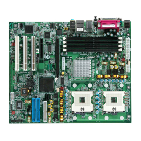
Motherboard Layout
The location of motherboard components is shown below.
P4SE
2–2 User’s Manual

Chapter 2
Motherboard Layout Key
These components, connectors and jumpers are located in the motherboard layout graphic on the
facing page.
Component Function
CPU mPGA478 CPU socket
AGP Accelerated Graphics Port
DDRA1, A2, B1, B2 DIMM sockets for DDR SDRAM
PCI1~ PCI5 32_bit PCI expansion slots
Connectors Function
J1394_2 Firewire internal connectors (P4SE-Gold/P4SG-Gold only)
JATXPWR1 ATX 12V power connector
JATXPWR2 Connectors for power supply
JPANEL1 Front panel feature connector
JUSB1, JUSB2 Internal USB connector
JCFAN1 CPU cooling fan power connector
JNB_FAN1 North Bridge cooling fan power connector
JGAME1 Game port connector
JAUX1AUX-auxiliary audio-in connector
JCDIN1 CD-ROM drive audio-in connector
JCOM2 COM2 port bracket connector
JCOM3 COM1 port bracket connector (P4SG/P4SG-Gold only)
SATA1, SATA2 Serial ATA drive connector
FDD1 Floppy disk drive connector
IDE1, IDE2 IDE drive connectors
JSFAN1, JSFAN2System cooling fan connectors
Jumpers Function
JCMOS1Clear CMOS
JCPUS1, JCPUS2 Frontside Bus clock frequency selection
JAUDIO1 Audio for front panel
User’s Manual 2 -3

P4SE Series Motherboard
JCMOS1: Clear CMOS Jumper
This jumper switch, JCMOS1, clears the CMOS Setup configuration that is stored in the real-time
clock’s CMOS memory. If configuration becomes corrupted, or if the CMOS settings are
changed to an unsuitable configuration, the motherboard may not work properly. JCMOS1lets
you delete the configuration data stored in CMOS memory and reset the CMOS to the Optimized
Defaults.
Follow the procedure below to clear CMOS memory.
1. Turn off and unplug the system and remove the system housing cover.
2. Set JCMOS1 to the Clear CMOS position by placing the jumper cap over pins 2 and 3 for
one minute.
3. Return the jumper cap to the Normal setting, pins 1 and 2.
4. Replace the system housing cover, plug in the system and power on.
5. Run the CMOS Setup Utility and load the Optimized Defaults. Make any custom settings
you require. (See Chapter 4, BIOS Settings.)
6. Save the settings as you exit the program and restart your computer.
2 -4 User’s Manual

Chapter 2
JCPUS1, JCPUS2: Frontside Bus Clock Frequency
These two jumper switches, JCPUS1and JCPUS2, set the clock frequency used to generate the
FSB speed, 100MHz~200MHz.
JAUDIO1:Audio for Front Panel
This jumper, JAUD1, allows users to switch audio function to the front panel if front
panel is installed.
User’s Manual 2 -5
1
2
10
9
JAUDIO1
Default,
Audio function
in rear panel
Audio to front panel
Pin Assignment:
2:
3:
5-6:
9-10:
GND
MIC
Line Out Left
Line Out Right
1
2
10
9
Line Out Right
Line Out Left
MIC
GND

P4SE Series Motherboard
CPU Socket & Cooling Fan / Heatsink Frame
The mPGA478B CPU socket supports a 478-pin Intel Pentium 4 processor. The Pentium 4 CPU
requires a cooling fan/heatsink, which attaches to the board using a retention mechanism
mounting frame. See the section on installing the CPU in Chapter 3.
AGP 8X 1.5V Slot
The AGP slot is for the exclusive use of high speed AGP video display cards. It is AGP 3.0
compliant. This AGP slot supports AGP4X and AGP8X card. This slot only supports 1.5V
devices. Do not use a 3.3V AGP card with this motherboard. The AGP slot is extended to include
support for AGP Pro cards using up to 50 watts of power.
2 -6 User’s Manual
AGP 8X, 4X slot
mPGA478B Socket:
This socket is for 478-pin
Pentium 4 CPUs only.
Fan/Heatsink assembly
retention mechanism

Chapter 2
ATX12V Power Connectors
The two power connectors let you attach two leads from an ATX12V power supply to the
motherboard. The ATX12V standard requires a 20-pin ATX connector plus a 4-pin ATX12V
connector. See the connector diagrams below.
User’s Manual 2 -7
JATXPWR2
JATXPWR1
ATX2X2,
12 V processor core voltage connector

P4SE Series Motherboard
System Memory Sockets
These DIMM system memory sockets support 400MHz (PC3200) or 333MHz (PC2700) or
266MHz (PC2100) DDR SDRAM system memory modules. See the section on installing
memory in Chapter 3.
PCI Expansion Slots
The PCI expansion slots let you install additional system hardware via add-on cards. There are
five 32-bit, 33MHz slots that are compliant with PCI 2.1/2.2 on this motherboard. See the section
on installing internal peripherals in Chapter 3.
2 -8 User’s Manual

Chapter 2
Drive Connectors
There are drive connectors on the motherboard for connecting IDE and floppy disk drives.
FDD1: Floppy Disk Drive Connector
The connector FDD lets you attach one floppy disk drive to the motherboard using a standard
FDD ribbon cable.
IDE1, IDE2: IDE Drive Connectors
The two IDE drive connectors are marked IDE1, the primary channel, and IDE2, the secondary
channel. Each connector supports two drives, a Master and a Slave.
JCOM2: COM2 Port Bracket Connector
The COM2 Port Bracket Connector lets you add an additional serial port, to which you can
connect peripherals such as serial modems and pointing devices. The COM2 port is configured in
the CMOS Setup Utility, see Chapter 4.
JCOM3: COM1Port Bracket Connector (P4SG/P4SG-Gold only)
User’s Manual 2 -9

P4SE Series Motherboard
SATA1, SATA2: Serial ATA Drive Connectors
There are two Serial ATA connectors on the motherboard. Each connector supports one
drive, which connects to the motherboard with a Serial ATA cable. The motherboard
comes with two Serial ATA cables and one power core for user’s convenience.
Serial ATA Interfaces
The ICH5’s Serial ATA controller offers two independent Serial ATA ports with a theoretical maximum
transfer rate of 150 MB/s per port. One device can be installed on each port for a maximum of two Serial
ATA devices. A point-to-point interface is used for host to device connections, unlike Parallel IDE which
supports a master/slave configuration and two devices per channel. For compatibility, the underlying Serial
ATA functionality is transparent to the operating system. The Serial ATA controller can operate in both
legacy and native modes. In legacy mode, standard IDE I/O and IRQ resources are assigned (IRQ 14 and
15). In Native mode, standard PCI resource steering is used. Native mode is the preferred mode for
configurations using the Windows XP and Windows 2000 operating systems.
NOTE1: Many Serial ATA drives use new low-voltage power connectors and require adaptors or power supplies equipped
with low-voltage power connectors. For more information, see: http://www.serialata.org/
2 -10 User’s Manual
More Information about S-ATA HDD:
Serial ATA drives are designed for easy
installation with no jumpers, terminators, or
other settings. It is not necessary to set any
jumpers on this drive for proper operation.
The jumper block adjacent to the signal
connector is for factory use only.

Chapter 2
JCDIN1& JAUX1: Audio Connectors
These two connectors, JCDIN1and JAUX1, let you attach audio-in cables from internal
peripherals, such as a CD-ROM or DVD-ROM drive. The connectors provide an audio input
connection between a device and the integrated audio subsystem.
J1394_2: IEEE-1394 Connectors
The connector, J1394_2, provide onboard support for devices using the IEEE-1394 standard. The
IEEE-1394 standard provides high speed digital interface for audio/ video appliances such as
digital video camcorders, digital television, storage peripherals and other PC portable devices.
User’s Manual 2 -11

P4SE Series Motherboard
JPANEL1: Front Panel Connector
This connector, J23, connects the following system housing front panel features:
• Reset Switch (Reset in diagram)
• IDE device LED (IDE LED in diagram)
• ACPI Suspend LED (ACPI in diagram)
• Power Switch (Power On in diagram)
• System Activity LED (System LED in diagram)
• Housing-mounted Speaker (Speaker in diagram)
JUSB1, JUSB2: Internal USB Connector
These connectors, JUSB1 and JUSB2, let you attach internal USB devices.
2 -12 User’s Manual

Chapter 2
JCFAN1, JNB_FAN1, JSFAN1,JSFAN2: CPU & System Fan Connectors
These 3-pin connectors provide power to the CPU cooling fan (JCFAN1), to North Bridge
cooling fan (JNB_FAN1), to the System cooling fans (SFAN1, SFAN2). A temperature monitor
detects the CPU and internal system temperatures. You can set a system shutdown temperature in
the PC Health section of the CMOS Setup Utility.
User’s Manual 2 -13

P4SE Series Motherboard
JGame1: Gameport connector
This connector, J47, is a standard 15-pin gameport connector for attaching game controlling
devices.
External I/O Ports
On the rear edge of the motherboard there are several external Input/Output ports. These ports are
color coded for easy identification.
2 -14 User’s Manual
Rear I/O of P4SE
-
Gold/P4SG
-
Gold
For P4SG-
Gold, COM port will be VGA port
Rear I/O of P4SE/P4SG
For P4SG, COM port will be VGA port
Table of contents
Other IWILL Motherboard manuals

IWILL
IWILL Motherboard DJ800 User manual

IWILL
IWILL wa133 User manual

IWILL
IWILL P6NS User manual

IWILL
IWILL DNS-SATA User manual

IWILL
IWILL FB24624100 User manual

IWILL
IWILL P4E Series User manual

IWILL
IWILL P4R533 User manual

IWILL
IWILL P4SP User manual

IWILL
IWILL KD266 User manual

IWILL
IWILL KK266Plus User manual

IWILL
IWILL mp4s Original operating instructions

IWILL
IWILL DK8X User manual

IWILL
IWILL DNS-SATA User manual

IWILL
IWILL piils User manual

IWILL
IWILL DN800 User manual

IWILL
IWILL DK8X User manual

IWILL
IWILL DP533 Series User manual

IWILL
IWILL mP4G2 Series User manual

IWILL
IWILL DH800 User manual

IWILL
IWILL DN800-SLI User manual