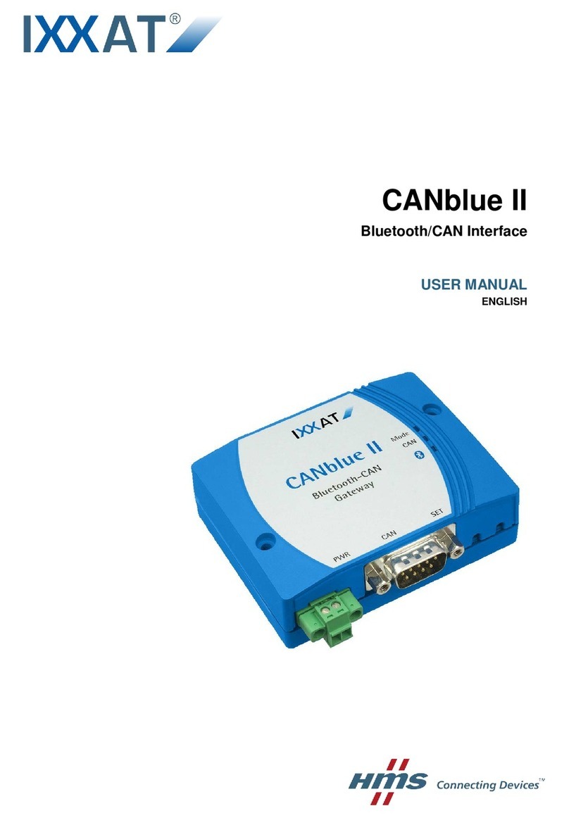
IXXAT CANblue II User manual

CANblue II
Extended User Manual
USER MANUAL
4.01.0126.20000 EN 3.2 ENGLISH

Important User Information
Liability
Every care has been taken in the preparation of this document. Please inform HMS Industrial Networks of any
inaccuracies or omissions. The data and illustrations found in this document are not binding. We, HMS Industrial
Networks, reserve the right to modify our products in line with our policy of continuous product development. The
information in this document is subject to change without notice and should not be considered as a commitment by
HMS Industrial Networks. HMS Industrial Networks assumes no responsibility for any errors that may appear in this
document.
There are many applications of this product. Those responsible for the use of this device must ensure that all the
necessary steps have been taken to verify that the applications meet all performance and safety requirements
including any applicable laws, regulations, codes, and standards.
HMS Industrial Networks will under no circumstances assume liability or responsibility for any problems that may
arise as a result from the use of undocumented features, timing, or functional side effects found outside the
documented scope of this product. The effects caused by any direct or indirect use of such aspects of the product
are undefined, and may include e.g. compatibility issues and stability issues.
The examples and illustrations in this document are included solely for illustrative purposes. Because of the many
variables and requirements associated with any particular implementation, HMS Industrial Networks cannot
assume responsibility for actual use based on these examples and illustrations.
Intellectual Property Rights
HMS Industrial Networks has intellectual property rights relating to technology embodied in the product described
in this document. These intellectual property rights may include patents and pending patent applications in the USA
and other countries.
CANblue II User Manual 4.01.0126.20000 EN 3.2

CANblue II User Manual 4.01.0126.20000 EN 3.2
Table of Contents Page
1 User Guide ........................................................................................................................ 5
1.1 Target Audience.............................................................................................................5
1.2 Related Documents .......................................................................................................5
1.3 Document History ..........................................................................................................5
1.4 Conventions ..................................................................................................................6
2 Safety Instructions.......................................................................................................... 7
2.1 Information on EMC .......................................................................................................7
2.2 General Safety Instructions.............................................................................................7
2.3 Bluetooth® Connection ..................................................................................................8
2.4 Intended Use.................................................................................................................8
3 Scope of Delivery ............................................................................................................ 8
4 Product Description ....................................................................................................... 9
4.1 Operation Modes ...........................................................................................................9
4.2 Features .......................................................................................................................9
5 Installation ...................................................................................................................... 10
5.1 Installing the Software ..................................................................................................10
5.1.1 Installing the Driver ............................................................................................... 10
5.1.2 Installing the CANblue II Software Package................................................................ 10
5.2 Connectors..................................................................................................................10
5.2.1 Power Connector.................................................................................................. 10
5.2.2 External Antenna.................................................................................................. 11
5.2.3 CAN Connector.................................................................................................... 11
5.3 Installing the Virtual COM Port ......................................................................................12
6 Configuration as PC Interface with VCI Driver ...................................................... 15
7 Configuration as Generic PC Interface or as Bridge............................................ 16
7.1 Configuration Tools ......................................................................................................16
7.1.1 Terminal Program ................................................................................................. 16
7.1.2 CANblueCon Configuration Tool .............................................................................. 16
7.1.3 Examples............................................................................................................ 18
7.2 Configuring an Interface ...............................................................................................18
7.3 Configuring a Bridge ....................................................................................................20
7.3.1 Bridge Chain ....................................................................................................... 21
7.4 Settings in Generic Mode..............................................................................................22
7.4.1 Configuring the Filter ............................................................................................. 22
7.4.2 Autostart............................................................................................................. 22

CANblue II User Manual 4.01.0126.20000 EN 3.2
Table of Contents
7.4.3 Changing the Message Format................................................................................ 22
7.4.4 Setting the Transmitting Time .................................................................................. 23
7.4.5 Reset to Factory Settings ....................................................................................... 23
7.4.6 Changing the Bluetooth Passkey ............................................................................. 24
7.4.7 Visibility.............................................................................................................. 24
7.4.8 Connection Security in Bridge Setup ......................................................................... 24
8 Operation......................................................................................................................... 25
8.1 Overview.....................................................................................................................25
8.2 Indicators ....................................................................................................................25
8.2.1 Mode LED........................................................................................................... 25
8.2.2 CAN LED............................................................................................................ 25
8.2.3 Bluetooth LED ..................................................................................................... 25
8.3 Connection Behavior....................................................................................................25
9 Errors and Troubleshooting ....................................................................................... 26
10 PC Interface Driver Network and Device Communication.................................. 28
11 Generic Mode Network and Device Communication ........................................... 28
11.1 ASCII Protocol.............................................................................................................28
11.2 CAN Commands..........................................................................................................29
11.2.1 Configuring the Communication Behavior .................................................................. 29
11.2.2 Initializing the CAN Controller.................................................................................. 32
11.2.3 Configuring the Filter ............................................................................................. 33
11.2.4 Starting the CAN Controller..................................................................................... 36
11.2.5 Stopping the CAN Controller ................................................................................... 36
11.2.6 Reset the CAN Controller ....................................................................................... 37
11.3 Device Commands.......................................................................................................38
11.3.1 Requesting Device Information ................................................................................ 38
11.3.2 MAC Commands for Connecting Devices .................................................................. 40
11.3.3 MAC Commands Security ...................................................................................... 42
11.3.4 Configuring the Device........................................................................................... 45
11.3.5 Reset the Device .................................................................................................. 49
11.4 CAN Messages in ASCII format ....................................................................................50
11.5 CAN Messages in Binary Format ..................................................................................51
11.6 Error Messages ...........................................................................................................52
12 Technical Data................................................................................................................ 53
13 Default Settings ............................................................................................................. 53
14 Support/Return Hardware ........................................................................................... 54
14.1 Support.......................................................................................................................54
CANblue II User Manual 4.01.0126.20000 EN 3.2
Table of Contents
14.2 Return Hardware .........................................................................................................54
15 Disposal........................................................................................................................... 54
A Regulatory Compliance............................................................................................... 55
A.1 EMC Compliance (CE) .................................................................................................55
A.2 FCC Compliance Statement .........................................................................................55
A.3 RoHs Directive.............................................................................................................56
A.4 Japan Radio Equipment Compliance (TELEC) ...............................................................56
B Disposal and recycling ................................................................................................ 56
C Measurements ............................................................................................................... 57
D Configuration Examples.............................................................................................. 58
D.1 Example 1: Connecting a CAN Network With a Computer ...............................................58
D.2 Example 2: Configuring a CAN Bridge ...........................................................................59
D.3 Example 3: Configuring a Bridge Chain .........................................................................61

This page intentionally left blank

User Guide 5 (62)
1 User Guide
Please read the manual carefully. Make sure you fully understand the manual before using the
product.
1.1 Target Audience
This manual addresses trained personnel who are familiar with CAN technology, Bluetooth®
wireless technology and the applicable national standards. The contents of the manual must be
made available to any person authorized to use or operate the product.
1.2 Related Documents
Document Author
Installation Guide VCI Driver HMS
User Manual of bus monitor in use HMS
VCI Software Design Guides (.NET, C, C++) HMS
1.3 Document History
Version Date Description
3.0 March 2017 Edited and revised in new design.
3.1 September 2018 Removed instructions for Windows XP, added bus off information, structural
changes in configuration chapters, added target audience and intended use
3.2 October 2018 Added commands for Slave MAC address list
CANblue II User Manual 4.01.0126.20000 EN 3.2

User Guide 6 (62)
1.4 Conventions
Instructions and results are structured as follows:
► instruction 1
► instruction 2
➨result 1
➨result 2
Lists are structured as follows:
• item 1
• item 2
Bold typeface indicates interactive parts such as connectors and switches on the hardware, or
menus and buttons in a graphical user interface.
This font is used to indicate program code and other
kinds of data input/output such as configuration scripts.
This is a cross-reference within this document: Conventions, p. 6
This is an external link (URL): www.hms-networks.com
Safety advice is structured as follows:
Cause of the hazard!
Consequences of not taking remediate action.
How to avoid the hazard.
Safety signs and signalwords are used dependent on the level of the hazard.
This is additional information which may facilitate installation and/or operation.
This instruction must be followed to avoid a risk of reduced functionality and/or
damage to the equipment, or to avoid a network security risk.
Caution
This instruction must be followed to avoid a risk of personal injury.
WARNING
This instruction must be followed to avoid a risk of death or serious injury.
CANblue II User Manual 4.01.0126.20000 EN 3.2

Safety Instructions 7 (62)
2 Safety Instructions
Risk of disturbances and interferences if used with WLAN at the same time!
Bluetooth®wireless technology and WLAN both work with the frequency of 2.4 GHz.
Caution
This equipment emits RF energy in the ISM (Industrial, Scientific, Medical) band.
Make sure that all medical devices used in proximity to this device meet appropriate
susceptibility specifications for this type of RF energy.
The CANblue II contains a small radio transmitter and receiver. During communication with
other Bluetooth products the CANblue II receives and transmits electromagnetic fields
(microwaves) in the frequency range 2.4 to 2.5 GHz. The output power of the radio transmitter
is very low. The exposure to transmitted RF energy while using the device is well below the
prescribed limits in all national and international RF safety standards and regulations.
2.1 Information on EMC
Risk of interference to radio and television if used in office or home environment!
Use exclusively included accessories. Use exclusively shielded cables.
Make sure that the shield of the interface is connected with the device plug and the
plug on the other side.
2.2 General Safety Instructions
► Protect product from moisture and humidity.
► Protect product from too high or too low temperature (see Technical Data, p. 53).
► Protect product from fire.
► Do not paint the product.
► Do not modify or disassemble the product. Service must be carried out by HMS Industrial
Networks.
► Store products in dry and dust-free place.
CANblue II User Manual 4.01.0126.20000 EN 3.2

Scope of Delivery 8 (62)
2.3 Bluetooth® Connection
Make sure that the following conditions are met:
• preferably unobstructed line of sight between the antennas of the devices
• minimum distance of 50 cm between the devices (to avoid interference)
• minimum distance of 10 m to WLAN recommended
Data transmission rate depends on:
• distance between the communicating devices
• obstacles between the devices
• environment (texture of walls etc.)
• device configuration
• signal conditions
2.4 Intended Use
The CANblue II is used to connect computer systems (like PC, notebook, tablet or smartphone)
to CAN networks via Bluetooth®wireless technology.
3 Scope of Delivery
Included in the scope of delivery:
• CANblue II
• CANanalyser Mini
• Installation Guide VCI Driver
• User Manual CANblue II
• CD with VCI driver and extended User Manual
CANblue II User Manual 4.01.0126.20000 EN 3.2

Product Description 9 (62)
4 Product Description
With the CANblue II multiple CAN networks can be connected wireless via Bluetooth®wireless
technology. The CANblue II forwards from the CAN network received messages to the
Bluetooth connection. The messages that are received via a Bluetooth connection are
transmitted to the CAN network and other existing Bluetooth connections.
The CANblue II provides an additional server. This connection can be used to configure the
CANblue II. Various operation modes are supported.
4.1 Operation Modes
PC interface
•VCI driver for Windows
– supported by the VCI driver
– operation with all IXXAT tools possible
– operation with other VCI-based application programs and tools possible
•Generic mode (ASCII/binary protocol )
– communication based on ASCII commands and optimized binary data transfer
– usable in all systems, for example embedded computer systems
– low latency
Bridge mode
• several CANblue II can be connected
• CANblue II can serve as Master and Slave
• transparent message exchange on layer 2
• can be used in DeviceNet, CANopen, J1939 and customer specific protocols
• use of CAN ID filters possible
4.2 Features
• Bluetooth®specification Bluetooth v4.0
• power supply 9 to 30 V DC
• ISO 11898-2 CAN bus coupling (9 pin D-Sub 9)
• available with internal or external antenna
• different external antennas available
• CAN controller initialization with automatic baud rate detection
• CAN message filtering
CANblue II User Manual 4.01.0126.20000 EN 3.2

Installation 10 (62)
5 Installation
Connection issues if the computer turns into sleep mode!
Deactivate the sleep mode of the computer the CANblue II is connected to. In case
of reconnecting problems see Errors and Troubleshooting, p. 26.
5.1 Installing the Software
5.1.1 Installing the Driver
For the operation of the CANblue II as VCI PC interface for Windows the VCI driver is needed.
► Install the VCI driver (see Installation Guide VCI Driver).
5.1.2 Installing the CANblue II Software Package
► Close all open applications.
► Make sure that all prior versions of the CANblue II software package are uninstalled.
► Insert the CD-ROM in the CD drive.
► Run CANblue_II_Generic_Setup.exe.
► Follow the instructions in the installation program.
5.2 Connectors
Fig. 1 Connectors
1 Power connector +
2 Power connector -
3 CAN connector
4 Button Reset to factory settings
5.2.1 Power Connector
The device is protected against polarity reversal.
Pin Allocation
Number Pin allocation Signal
1+9 to 30 V DC
2-GND
1
2
3
4
CANblue II User Manual 4.01.0126.20000 EN 3.2

Installation 11 (62)
5.2.2 External Antenna
Fig. 2 Connector for external antenna
► Screw the external antenna on connector (1).
► Use exclusively antennas that are approved by HMS Industrial Networks (by reason of
radio certification).
► For further information about different antennas see www.ixxat.com.
5.2.3 CAN Connector
Pin Allocation of D-Sub 9 Connector
Pin no. Signal
1–
2 CAN low
3 GND
4–
5–
6–
7CAN high
8–
9–
1
CANblue II User Manual 4.01.0126.20000 EN 3.2

Installation 12 (62)
5.3 Installing the Virtual COM Port
The CANblue II provides two virtual servers: Config and SPP. For the configuration of the
CANblue II a Bluetooth-capable device that supports the serial port profile (SPP) must be
connected to the Config server via a virtual COM port.
Windows 7, 8 and 10
► In Windows task bar right-click on the Bluetooth icon and select Add a device.
➨All available devices are displayed.
➨CANblue II devices are named IXXAT CANblue II ([MAC address]).
Fig. 3 Add a device
► Check the MAC address of the CANblue II that is printed on the back of the device.
► Select the device to connect and click button Next.
Fig. 4 Add a device
CANblue II User Manual 4.01.0126.20000 EN 3.2

Installation 13 (62)
► Select Enter the device’s pairing code and click button Next.
Fig. 5 Pairing code
► Enter the default pairing code 7388 and click button Next.
➨Added device is displayed in window Devices and Printers.
Some Bluetooth drivers do not ask for a pairing code. In this case pairing is possible without code.
Determine the correct COM port:
Fig. 6 Devices and printers
► In window Devices and Printers right-click on the newly added CANblue II and in the
context menu select Properties.
CANblue II User Manual 4.01.0126.20000 EN 3.2

Installation 14 (62)
➨Window CANblue II Properties is opened.
Fig. 7 CANblue II properties
➨Two SPP server of the device are displayed.
➨With the displayed COM port of Serial port (SPP) ‘Config’ (1) a connection to the
CANblue II can be established.
➨The COM port of Serial port (SPP) ‘SPP’ is reserved for a connection between two
CANblue II devices.
► Make sure that both checkboxes of Serial port (SPP) ‘Config’ and of Serial port (SPP)
‘SPP’ are activated.
If the checkboxes are not activated the driver may not be correctly installed. To download the
driver, make sure that an internet connection is established.
► Click button Apply.
➨The COM port of Serial port (SPP) ‘Config’ can be used to connect to the CANblue II
CANblue II User Manual 4.01.0126.20000 EN 3.2

Configuration as PC Interface with VCI Driver 15 (62)
6 Configuration as PC Interface with VCI Driver
The CANblue II can be configured as a PC interface with the VCI driver for Windows.
HMS recommends to reset the device to factory settings for optimal performance.
Parallel usage with bridge mode is possible with reduced receive and transmit performance.
Existing CAN filters are cleared in VCI mode and restored when the VCI mode is closed.
► Make sure that the VCI driver and the CANblue II software package are installed (see
Installing the Software, p. 10).
► Make sure that the virtual Config COM port is installed (see Installing the Virtual COM Port,
p. 12).
► Install the hardware according to the instructions in the Installation Guide VCI Driver.
► Make sure to access the Device Server Control with administrator rights.
► Configure the device with a VCI based tool, for example with the canAnalyser Mini
(included on delivery CD).
► To test if the device is connected, check the list of available devices in the canAnalyser
Mini.
CANblue II User Manual 4.01.0126.20000 EN 3.2

Configuration as Generic PC Interface or as Bridge 16 (62)
7 Configuration as Generic PC Interface or as
Bridge
The CANblue II can be configured as Generic PC interface or as Bridge both with two different
configuration tools.
7.1 Configuration Tools
To configure the CANblue II a terminal program or the CANblueCon Configuration Tool can be
used. Loading of existing configurations (txt- and bat-files) and the use of local commands is
only possible with the CANblueCon Configuration Tool.
7.1.1 Terminal Program
► Make sure that the CANblue II Software package is installed (see Installing the CANblue II
Software Package, p. 10).
► Make sure that the virtual Config COM port is installed (see Installing the Virtual COM Port,
p. 12).
► Select the setting serial and the correct COM port.
► Start the terminal program.
► Activate the local echo.
► Activate transmitting of carriage return and linefeed with Enter key at the end of an
entered command.
► Enter the virtual Config COM port.
➨Device is connected.
► Configure a generic interface (see Configuring an Interface, p. 18) or a Bridge (see
Configuring a Bridge, p. 20).
► Use ASCII commands to configure the device and observe the following:
– Enter the commands in capital letters.
– Execute the commands with key Enter.
– See Generic Mode Network and Device Communication, p. 28 for further information
about the commands.
7.1.2 CANblueCon Configuration Tool
Configuration examples for a generic interface and a bridge are included on the delivery CD in the
folder CANblueCon Examples. The examples can be loaded with the CANblueCon Configuration
Tool.
bat-files can be started directly from the file.
Adjust the COM port in the bat-file with an editor and in bridge configurations adjust the MAC
address in the txt-file. To start the bat-file in the CANblueCon Configuration Tool, double-click the
bat-file.
► Make sure that the CANblue II Software package is installed (see Installing the CANblue II
Software Package, p. 10).
CANblue II User Manual 4.01.0126.20000 EN 3.2

Configuration as Generic PC Interface or as Bridge 17 (62)
► Make sure, that the virtual Config COM port is installed (see Installing the Virtual COM Port,
p. 12).
► Start the command line.
► Enter the path to the CanBlueCon.exe.
To load an existing configuration:
► In bridge configurations adjust the MAC address in the txt-file.
► Enter CanBlueCon.exe <CONFIG_COM_PORT_NUMBER> <FILE_NAME> in the command
line.
➨Batch mode is started.
➨Commands are read from the configuration file.
To define a new configuration:
► Enter CanBlueCon.exe <CONFIG_COM_PORT_NUMBER>.
➨Interactive mode is started.
► Configure a generic interface (see Configuring an Interface, p. 18) or a Bridge (see
Configuring a Bridge, p. 20).
► Use ASCII commands to configure the device and observe the following:
– Execute the commands with key Enter.
– See Generic Mode Network and Device Communication, p. 28 for further information
about the commands.
The CANblueCon configuration tool supports a command history. Scrolling through former
commands is possible with the keys Up and Down.
Local Commands
Additionally to the ASCII commands local commands are supported by the CANblueCon. The
commands are interpreted locally and allow for example the implementation of cyclic
transmission. Local commands are useful if a configuration is planned to be used in Batch
mode of the CANblueCon, for example to implement loops or prints on screen.
Additional Commands with CANblueCon Configuration Tool
Command Parameter Description
#delay <DELAY_TIME> Delays the execution for the
specified time in seconds.
#goto <LABEL_NAME> Continues the execution from the
string where the label is defined.
#help -Shows a help screen.
#label <LABEL_NAME> Defines a label.
#pause -Waits until any key is pressed.
#print <TEXT> Prints <TEXT> on the display.
#exit -Closes the CANblueCon.
CANblue II User Manual 4.01.0126.20000 EN 3.2

Configuration as Generic PC Interface or as Bridge 18 (62)
7.1.3 Examples
CANblue II command and CANblue II reply:
>c can_init 1000
I OK: CAN_INIT
Local command and local output:
>#print CANblue Generic
# CANblue Generic
7.2 Configuring an Interface
The installed virtual Config COM port is used to configure the CANblue II to exchange data with
a CAN network connected to the CANblue II.
► Make sure, that the software package and the virtual COM port are installed.
► Start and configure the desired configuration tool (see Configuration Tools, p. 16).
► Reset the device to factory settings with command D SETTINGS_DEFAULT.
➨Existing filters and settings are deleted.
➨Factory settings are set (information about settings see Reset to Factory Settings, p.
23).
► Initialize the CAN controller with the desired baud rate with command
C CAN_INIT <baudrate>.
► Set the filter (see Configuring the Filter, p. 22).
► Specify further settings (see Settings in Generic Mode, p. 22).
► Check the configuration with command C CONFIG SHOW.
► Save the configuration with command C CONFIG SAVE.
► Start the CAN controller with command C CAN_START.
➨If the CAN controller receives a message from the CAN network that matches one of
the filters, the message is transmitted on the Bluetooth connection in ASCII format.
CANblue II
CAN connector
Bluetooth
connection
(SPP-Server)
CAN bus 1
PC
Bluetooth
Config
Slave
Master
Bluetooth connection
CANblue II User Manual 4.01.0126.20000 EN 3.2
Other manuals for CANblue II
1
Table of contents
Other IXXAT Gateway manuals

IXXAT
IXXAT CME/PN User manual

IXXAT
IXXAT CANbridge User manual

IXXAT
IXXAT CME/PN User manual

IXXAT
IXXAT SG Gateway User manual

IXXAT
IXXAT LIN2CAN User manual

IXXAT
IXXAT CANblue II User manual

IXXAT
IXXAT CAN@net User manual

IXXAT
IXXAT CAN@net II/Generic User manual

IXXAT
IXXAT CANio 250 Instruction manual

IXXAT
IXXAT CANio 500 Instruction manual
Popular Gateway manuals by other brands

Advantech
Advantech EKI-1222 user manual

Avaya
Avaya Media Gateway G250 Administration

LINOVISION
LINOVISION IOT-G65 quick start guide

Eagle
Eagle Fusion Quick reference guide

Grandstream Networks
Grandstream Networks BroadWorks BroadSoft GXW-400X user manual

Ruckus Wireless
Ruckus Wireless Metro Broadband Gateway Quick setup guide