Contents
1Introduction..................................................................................5
1.1 Overview ............................................................................... 5
1.2 Features ................................................................................ 5
1.3 Versions ................................................................................ 5
1.4 Block diagram....................................................................... 6
1.5 Support................................................................................. 7
1.6 Returning hardware ............................................................. 7
2Aluminum Version ........................................................................8
2.1 Pin Allocation........................................................................ 8
2.1.1 Voltage supply (X1).....................................................8
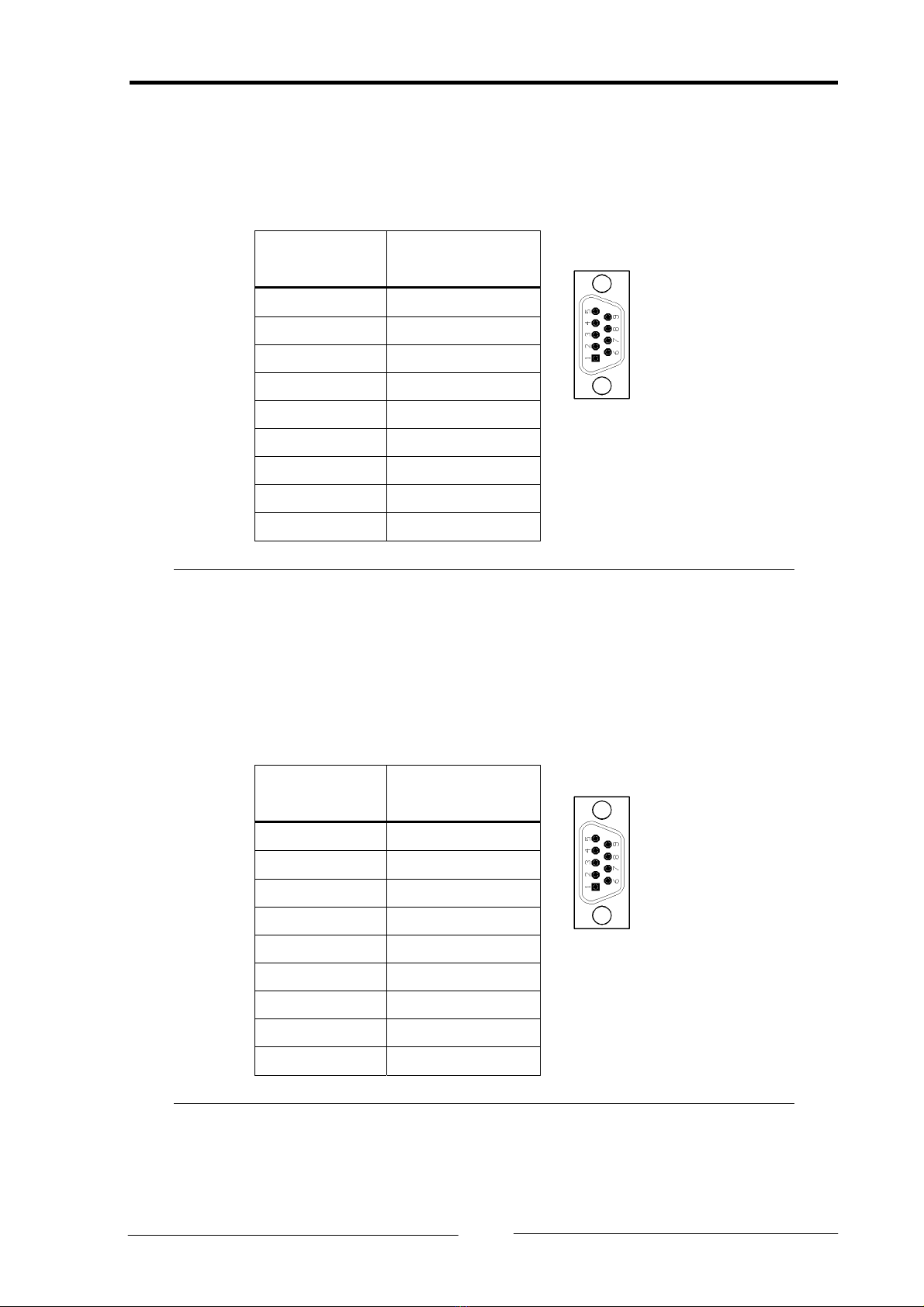
2.1.2 Serial interface RS232 (X2) ...........................................9
2.1.3 CAN 1 (X3) ...................................................................9
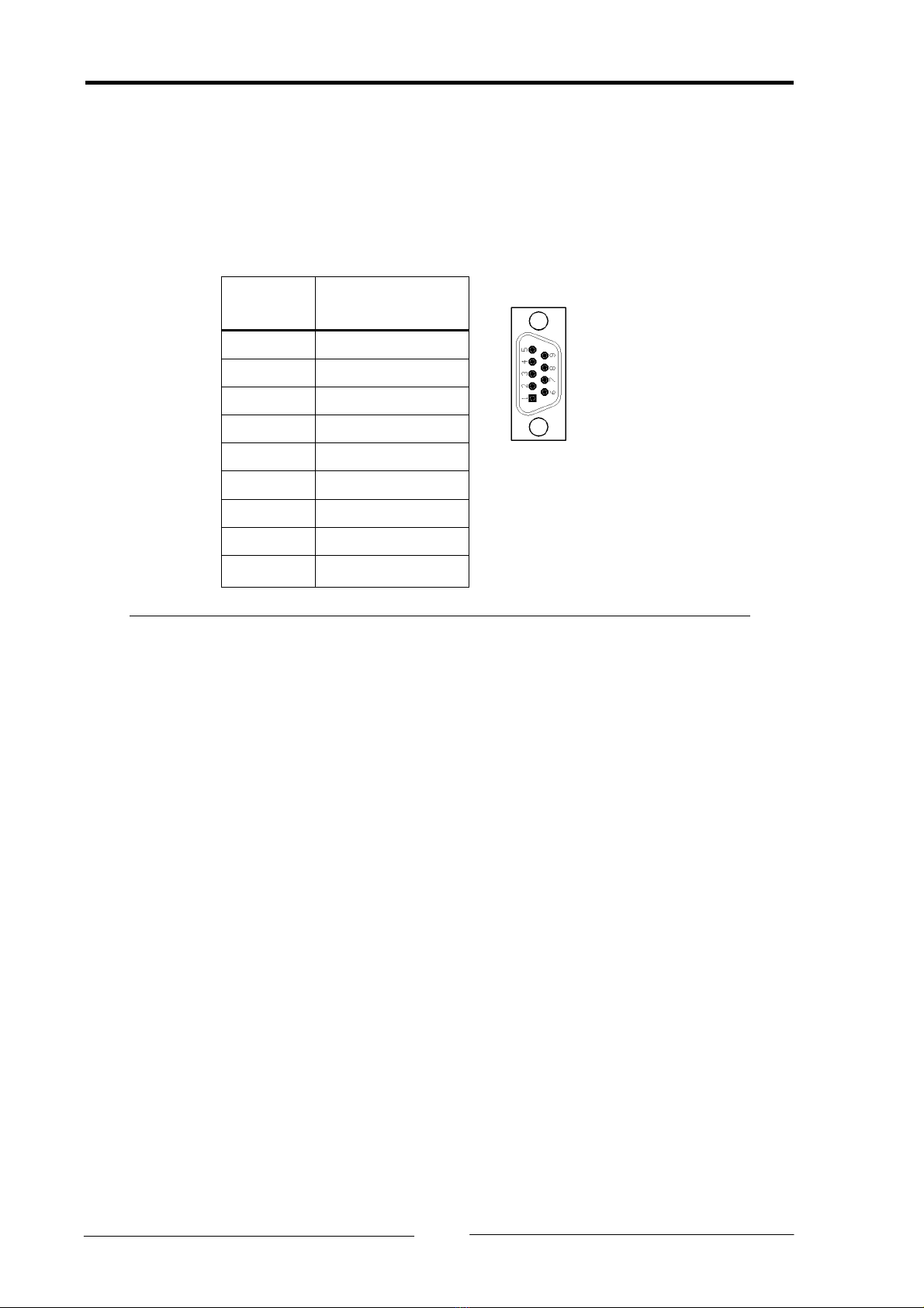
2.1.4 CAN 2 (X4) .................................................................10
2.2 Ground connections ........................................................... 10
3Industrial DIN-Rail Version .........................................................11
3.1 Pin allocation ...................................................................... 11
3.1.1 Voltage supply (X1)...................................................11
3.1.2 Serial interface RS232 (X2) ........................................12
3.1.3 CAN 1 (X3) .................................................................12
3.1.4 CAN 2 (X4) .................................................................13
3.2 Ground connections ........................................................... 13
4Displays.......................................................................................14
4.1 Normal mode (Gateway mode).......................................... 14
4.1.1 PWR - LED ..................................................................14
4.1.2 CAN1/CAN2 LED.........................................................14
4.1.3 COM LED....................................................................14
4.2 Automatic baudrate detection ........................................... 14
4.2.1 PWR LED ....................................................................14
4.2.2 CAN1/CAN2 LED.........................................................14
5Functional description................................................................15
5.1 Introduction........................................................................ 15
5.2 Data Structure of the Configuration Files .......................... 16
5.2.1 General settings [General] ........................................18
Copyright IXXAT Automation GmbH CANbridge - Manual, V1.4
3