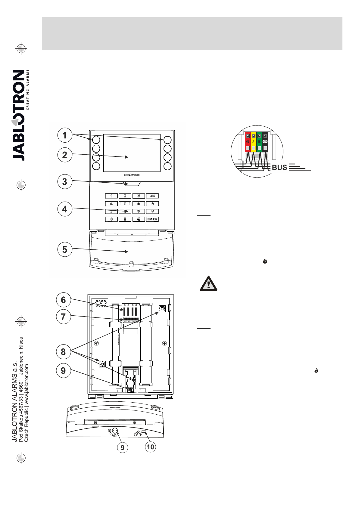
JA-115E, JA-115E-GR, JA-115E-AN BUS four-segment keypad with
display and RFID reader
Typ: 1KPAD2201LU
JA-115E, JA-115E-GR, JA-115E-AN 2 / 3 MLU510603
Authorization – setting and unsetting requires user authorization.
When this parameter is disabled the segment can be operated
without authorization. By disabling the parameter, the specific
segment can be controlled without authorization, except for the
Unset section function, for which authorization is always required.
For switching PG outputs on and off, the setting of the
Authorization / no authorization function applies to both states.
When switching PG outputs on and off, the Authorization / No
Authorization function is enabled for both states.
Common segment – settings and description of function
One of the other functions of the segment is called Common
segment (max 1 common segment can be set per keypad). This
simulates the simultaneous pressing of several segments controlling
sections located on this keypad. The selection of sections assigned
to a common segment is done via F-Link - Devices tab, at the
module position select Internal Settings, Segments tab and select
the function called Common segment A by selecting the segment.
The overview of segments that will be controlled at once is visible in
the newly displayed Common Segment tab.
If the status of the segments controlled by the Common segment
is different, the remaining segments will be set/unset after its use.
If one of the selected segments has the Partial setting function
enabled, then the Common Segment respects this setting: 1st press
of the Set button = partial setting, 2nd press of the Set button = full
setting.
The Common segment function should not be combined with the
Section / Common section function.
Common segment indications:
Green = all sections are unset fully
Yellow = sections are in various states or all of them are
set partially
Red = all sections are set fully
In the Settings tab, you can adjust the remaining keypad
parameters such as acoustic indication, backlight intensity, RFID
reader function, optical indication and display settings. Details of the
settings can also be found in the F-Link SW mouseover help bubble.
The Settings tab
Acoustic indication
It is set without dependence on the optical indication. The keypad
can indicate entry and exit delays or alarms. The acoustic indication
of the entry delay is silenced for the duration of the authorization. Exit
delays and alarms are indicated until the end of the pre-set time
unless the system indicator button (3)/keypad cover (5) is pressed.
Volume - Adjusts the keypad volume level in three levels: Low,
*medium and high
Alarms – continuous tone
Entry delay –continuous tone
Exit delay – slow beeping
Exit delay when partially set – slow beeping (disabled from
default).
Segment status change – beeps once when a status is changed
Function:
RFID reader – In order to save energy, you can limit the reader's
operation with the following options:
−Permanently ON – the RFID reader is always active. A BUS
keypads ignores wake up settings.
−Activated by pressing – when the keypad is activated the
RFID reader wakes up for 3 seconds.
−Disabled – the RFID reader is permanently disabled.
−Activated by pressing or authorization request – the
keypad wakes up after pressing a button on a keypad cover or
by an authorization request.
Optical indication
System indicator / button (3) – indicates the system status,
according to the following priorities from highest to lowest:
1 – Service indication:
1) Flashes yellow twice every 2 seconds – Service mode
2) Flashes green 2x every 2 seconds – Maintenance mode
3) Slow flashing yellow – Keypad is in BOOT mode, which is
used when updating firmware
2 – Operational indications:
1) Flashing yellow – Keypad not taught into system
2) Rapidly flashing red – Alarm in system
3) Flashes red 2x every 2 seconds – Alarm memory
indication
4) Flashes yellow (8 Hz) – Unsuccessful setting indication
5) Permanent yellow light – Fault
6) Flashes green (2 Hz) – Authorized user
7) Permanent green light – Normal operation. Everything is
OK, no faults
3 – Combined indications:
1) Flashes alternately green / red – Authorized user and
alarm / alarm memory indication
2) Flashes alternately green / yellow – Authorized user and
an active fault indication
4 – Indication in power save mode:
1) Flashes red once every 2 seconds – Alarm memory
indication for keypad in power save (sleep) mode (only valid
for system profiles EN 50131-1 and Incert).
2) Flashes yellow once every 2 seconds – Fault indication
(only valid for system profiles EN 50131-1 and Incert).
3) No indication – Sleep mode
Segments– there is no indication if the system is in the service
mode or if the segment has no function programmed. The PG optical
indication on the segment can be inverted.
Keypad indication is adjustable in six levels:
1) Indicates permanently – the keypad indicates
permenently. When the mains power to the control panel is
disconnected it switches to a lower indication level. Then the
mains power is restored the keypad indicates permanently
again.
2) Section / PG status change on keypad – the keypad
indicates when the section / PG status changes. The change
of state is indicated only on that segment. Entry delay and
alarm is indicated by the entire keypad.
3) Section / PG status change on segment – the keypad
indicates when the section / PG status changes. Segment
status change, arrival delay and alarm is indicated only on
that segment.
4) Segment status change on keypad – the keypad indicates
when the segment status changes (setting, unsetting,
PG on, PG off). The status change is indicated only on the
segment.
5) Entry delay / Alarm on segment – the keypad indicates the
entry delay and alarm on a specific segment.
6) Wake-up by pressing – the keypad optically indicates only
after opening the front cover (5), pressing a key or segment.
Other optional functions:
−Indicates PG status changes
−Indicates Unset
−Indicates Set status
Unset a section by authorization only during entry delay –
using an access code or an RFID tag/card will unset a section where
an entrance delay has been triggered (if the user has access to the
section). WARNING: This function is not recommended when the
control panel is configured to use a Common section. Unwanted
unsetting may occur to all sections assigned to the Common section
or it may even occur to the whole control panel (when pressing the
Unsetting button is followed by authorization).
Delayed panic (s) – this function triggers a panic alarm (silent or
loud) with an adjustable delay during which the alarm can be
cancelled. Activation and deactivation is done by a segment button
configured to Silent panic or Audible panic. Pressing the red segment
button (right) starts the timing and pressing the green segment
button cancels the timing. When authorization is enabled then it is
required for activation and deactivation. The delay is adjustable from
1 to 255 seconds.
Keypad light intensity in DAY / NIGHT mode.
Segments – segment button light intensity setting
Keypad –numeric keypad backlight setting
Display – LCD backlight setting