JA-155E, JA-155E-GR, JA-155E-AN Wireless four-segment keypad with
display and RFID reader
Typ: 5KPAD2202LU
JA-155E, JA-155E-GR, JA-155E-AN 2 / 3 MLU510701
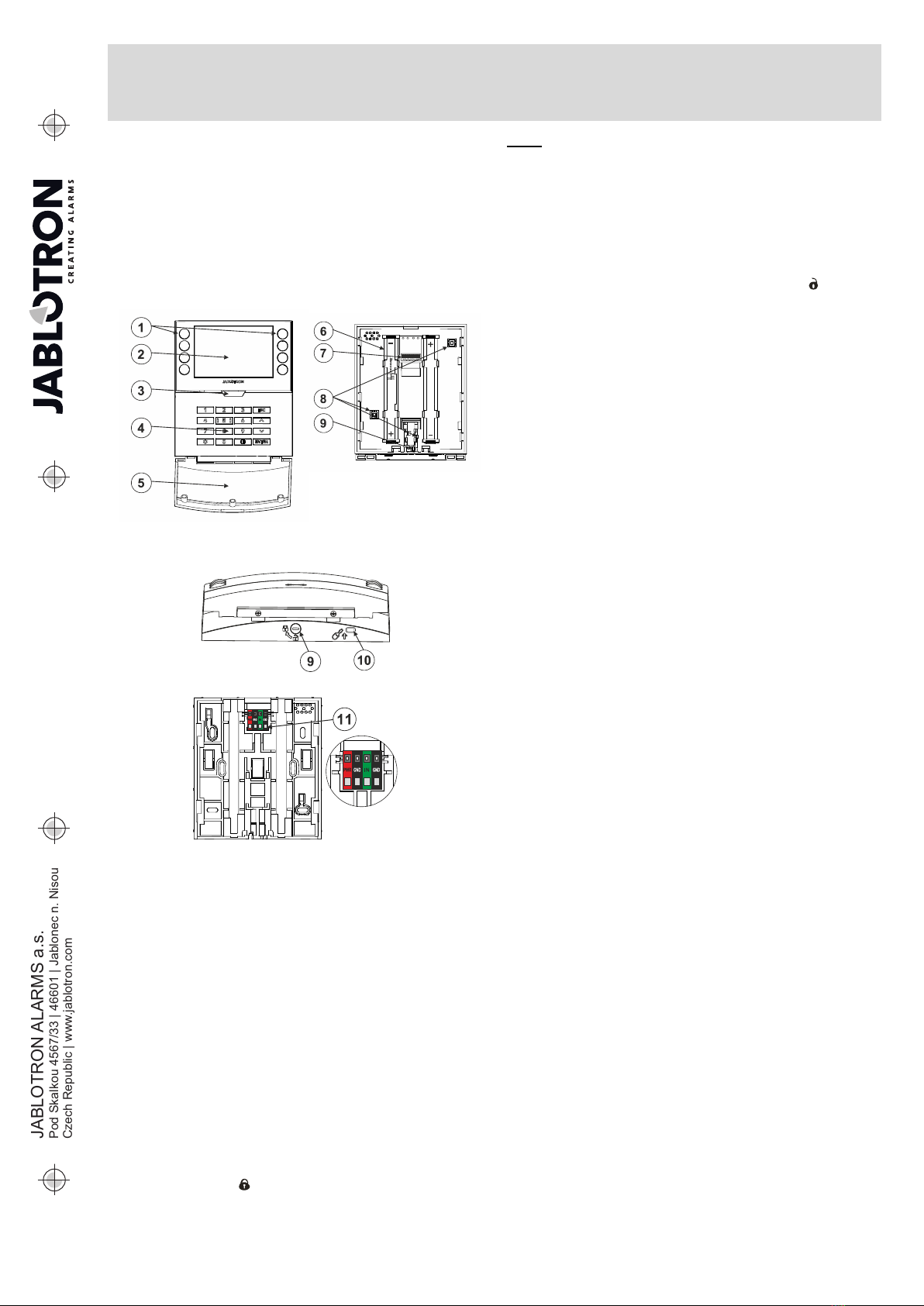
Alternative power supply
The keypad can be supplied from an external power supply with
12 V DC connected in PWR a GND terminals, see figure no. 5. You
can use the DE 06-12 Power adaptor suitable for concealed
installation. If the alternative power supply is connected, leave the
batteries inserted to ensure operation in the event of a mains power
failure or an external power supply being disconnected. The inserted
batteries are not recharged by an external power supply. If an
external power supply is connected, a permanent indication can be
switched on.
Installation of a magnetic contact
The keypad supports connection of a door detector. The IN input
reacts to being disconnected from the common GND terminal, see
figure no. 5. The control panel´s reaction to an activated IN input is
configurable in the F-Link SW. The input has a status response.
PWR – red, positive pole of an external power supply +12 V DC
GND – black, negative pole of an external power supply
IN – green, input terminal for door (magnetic) contact
GND – black, input terminal for door (magnetic) contact
Figure 5: magnetic contact connection
Changing the batteries
The keypad automatically checks the status of the batteries, and if
the battery voltage drops below the limit specified in the Technical
Parameters section, the keypad informs the system that the batteries
need to be replaced. Batteries should be replaced within 2 weeks of
the low battery report. The control panel must be switched into
Service or Maintenance mode before removing the keypad from the
back part (otherwise a tamper alarm will be triggered).
Note:In order to make sure the keypad works correctly, we recommend
using batteries supplied by the distributor or other quality brand alkaline
batteries.
The Settings tab
Acoustic indication
It is set without dependence on the optical indication. The keypad
can indicate alarms, entry and exit delays. The acoustic indication of
the entry delay is silenced for the duration of the authorization. Exit
delays and alarms are indicated until the end of the pre-set time
period unless the system indicator button (3)/keypad cover (5) is
pressed.
Volume - Adjusts the keypad volume level in three levels: Low,
*medium and high
Alarms – continuous tone
Entry delay –continuous tone
Exit delay – slow beeping
Exit delay when partially set – slow beeping (disabled from
default).
Segment status change – beeps once when a status is changed
Function:
RFID reader – In order to save energy, you can limit the reader´s
operation with the following options:
−Permanently ON – The RFID reader is always ON. This
setting is valid only if the keypad is permanently powered from
an external source, otherwise their RFID reader is always
switched off automatically.
−Activated by pressing – when the keypad is activated the
RFID reader wakes up for 3 seconds.
−Disabled – the RFID reader is permanently disabled.
−Activated by pressing or authorization request – the
keypad wakes up after pressing a button on a keypad cover or
by an authorization request.
Optical indication
System indicator / button (3) – indicates the system status,
according to the following priorities from highest to lowest:
1 – Service indication:
1) Flashes yellow twice every 2 seconds – Service mode
2) Flashes green 2x every 2 seconds – Maintenance mode
3) Slow flashing yellow – Keypad is in BOOT mode, which is
used when updating firmware
2 – Operational indications:
1) Flashing yellow – Keypad is not enrolled into system
2) Rapidly flashing red – Alarm in system
3) Flashes red 2x every 2 seconds – Alarm memory indication
4) Flashes yellow (8 Hz) – Unsuccessful setting indication
5) Permanent yellow light – Fault
6) Flashes green (2 Hz) – Authorized user
7) Permanent green light – Normal operation. Everything is OK,
no faults
3 – Combined indication:
1) Flashes alternately green / red – Authorized user and
alarm / alarm memory indication
2) Flashes alternately green / yellow – Authorized user and an
active fault indication
4 – Indication in power save mode:
1) Flashes red once every 2 seconds – Alarm memory
indication for keypad in power save (sleep) mode (only valid
for system profiles EN 50131-1 and Incert)
2) Flashes yellow once every 2 seconds – Fault indication
(only valid for system profiles EN 50131-1 and Incert).
3) No indication – Sleep mode
Segments – there is no indication if the system is in the service
mode or if the segment has no function programmed. The PG optical
indication on the segment can be inverted.
Keypad indication is adjustable in six levels:
1. Indicates permanently – the keypad indicates
permanently. When the mains power to the control panel is
disconnected it switches to a lower indication level. Then the
mains power is restored the keypad indicates permanently
again.
2. Section / PG status change on keypad – the keypad
indicates when the section / PG status changes. The change
of state is indicated only on that segment. Entry delay and
alarm is indicated by the entire keypad.
3. Section / PG status change on segment - the keypad
indicates when the section / PG status changes. Segment
status change, arrival delay and alarm are indicated only on
that segment.
4. Segment status change on keypad – the keypad indicates
when the segment status changes (setting, unsetting,
PG on, PG off). The status change is indicated only on the
segment.
5. Entry delay / Alarm on segment – the keypad indicates the
entry delay and alarm on a specific segment.
6. Wake-up by pressing – the keypad optically indicates only
after opening the front cover (5), pressing a key or segment.
Other optional functions:
−Indicates PG status changes
−Indicates Unset status
−Indicates Set status
−External input – enables the input for an external magnetic
contact
Unset a section by authorization only during entry delay -
using an access code or an RFID tag/card will unset a section where
an entrance delay has been triggered (if the user has access to the
section).
WARNING: This function is not recommended when the control
panel is configured to use a Common section. Unwanted unsetting
may occur to all sections assigned to the Common section or it may
even occur to the whole system (when pressing the Unsetting button
is followed by authorization).