The JA-63F wireless keypad
The JA-63F keypad is designed to control and progra alar syste s of
Jablotron’s JA-60 series. The keypad is equipped with backlit keys, built-in
LED signalling, acoustic signalling, and a display. It conveys infor ation
about the syste status in a convenient way. The keypad co unicates
wirelessly.
The keypad has a single input which is designed for door contact con-
nections. Any undesirable ishandling of the keypad (like opening its hous-
ing or tearing the keypad off its position) will trigger ta per signalling. In ad-
dition, the nu ber of atte pts to enter an access code is checked not to ex-
ceed a given li it. The keypad perfor s regular auto-testing and reports its
condition (including loss of co unication) regularly to the syste for full
supervision.
nstallation
Select the desired keypad location close to the building’s entrance. Under
opti u conditions in an open area, the keypad’s co unication range is
about 80 eters. Indoors the distance of the keypad fro the control panel
should not exceed 20 eters. Before fixing to the desired location check the
keypad’s radio co unication with the control panel. The need for a good
quality radio connection ust be taken into account during installation. The
keypad communicates bi-directionally and any radio communication
obstructions or interference can reduce the operating distance.
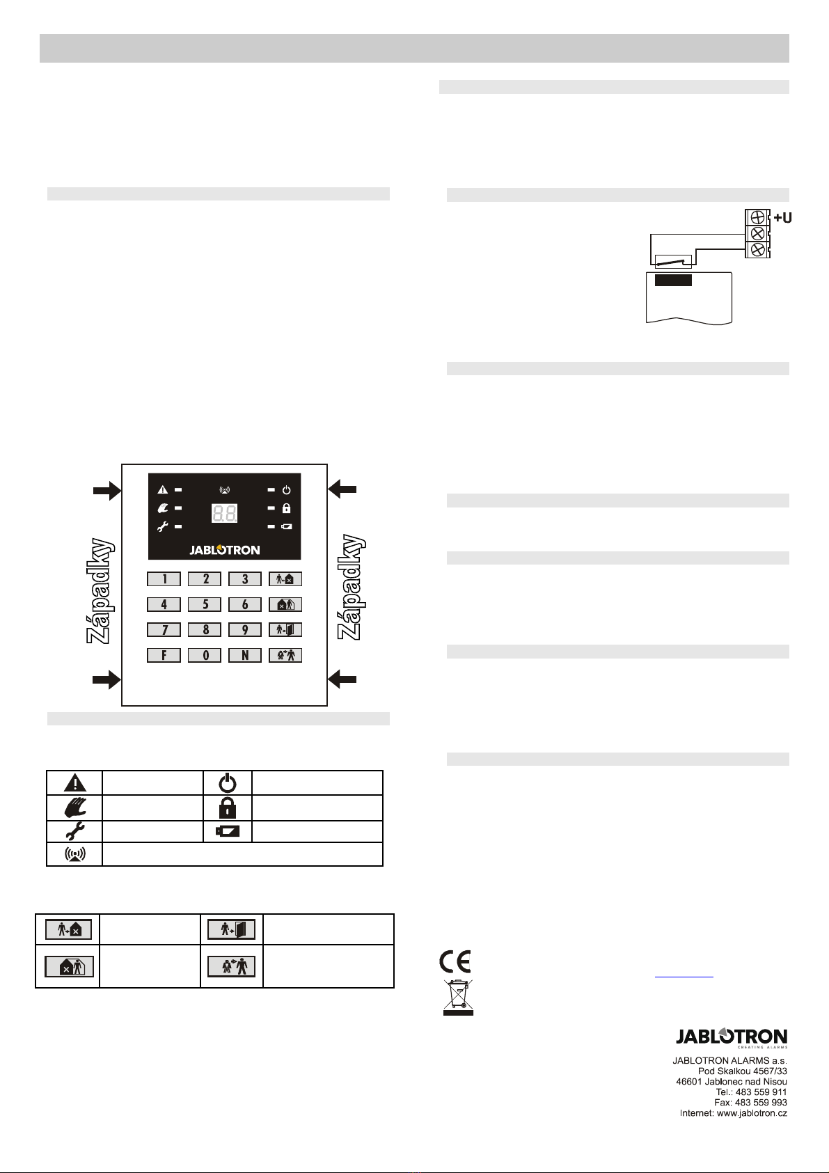
1. Open the keypad’s rear housing (by pressing the two tabs on the left or
right side).
2. Enter enroll ent ode on the control panel (see the control panel install-
ation anual) and insert the battery into the keypad.
3. Battery insertion will trigger enroll ent to the control panel.
4. Exit enroll ent ode by pressing the N key and test the keypad func-
tions fro the desired location.
5. When using with an external door detector, wire up the detector to the
INP and GND ter inals.
6. Mount the rear housing onto the desired location.
7. Close the keypad’s housing (attach the front housing on one side and
push it on the other side).
Operation
The keypad can operate and progra the syste to the full extent as it is
described in the control panel anual.
The following table describes the eaning of sy bols on the keypad LED
indicators:
Alar Power supply
Ta per Set (Ar ed)
Fault Battery
Wireless co unication indication
Functions F1 through F0 can be used as described in the control panel
anual. Besides this, there are 4 extra keys with the following functions:
Setting (Arming)
(equal to F1 entry)
Door opening
(equal to F3 entry)
Partial setting
(equal to F2 entry)
Panic (access under
duress)
(equal to F7, before ac-
cess code entry)
Keypad sleep mode
When battery-powered, the keypad saves energy by turning itself off after
10 seconds of inactivity. After then, the keypad will not indicate system
status, neither will it be able to indicate acoustically that an entrance
delay has begun. The keypad is woken up by pressing any key or triggering
a connected wired door detector.
If the keypad unit is powered by an AC adaptor there is no sleep ode.
The syste status is indicated per anently and the keypad is also capable
of acoustic indication.
External door detector
If a door detector is wired up then its triggering (by the detector’s loop dis-
connection) has the sa e effect as
pressing a key. This will exit keypad
sleep ode and the keypad will display
the current syste status. If the sys-
te is set (ar ed) then the entrance
delay will start – this eans that the
keypad will si ultaneously behave as
a door detector.
Short circuit ter inals INP and GND
if the input is not used.
Note: The lifetime of the battery is reduced proportionally to how fre-
quently the door detector is triggered and how often and how long the
keypad is battery-powered.
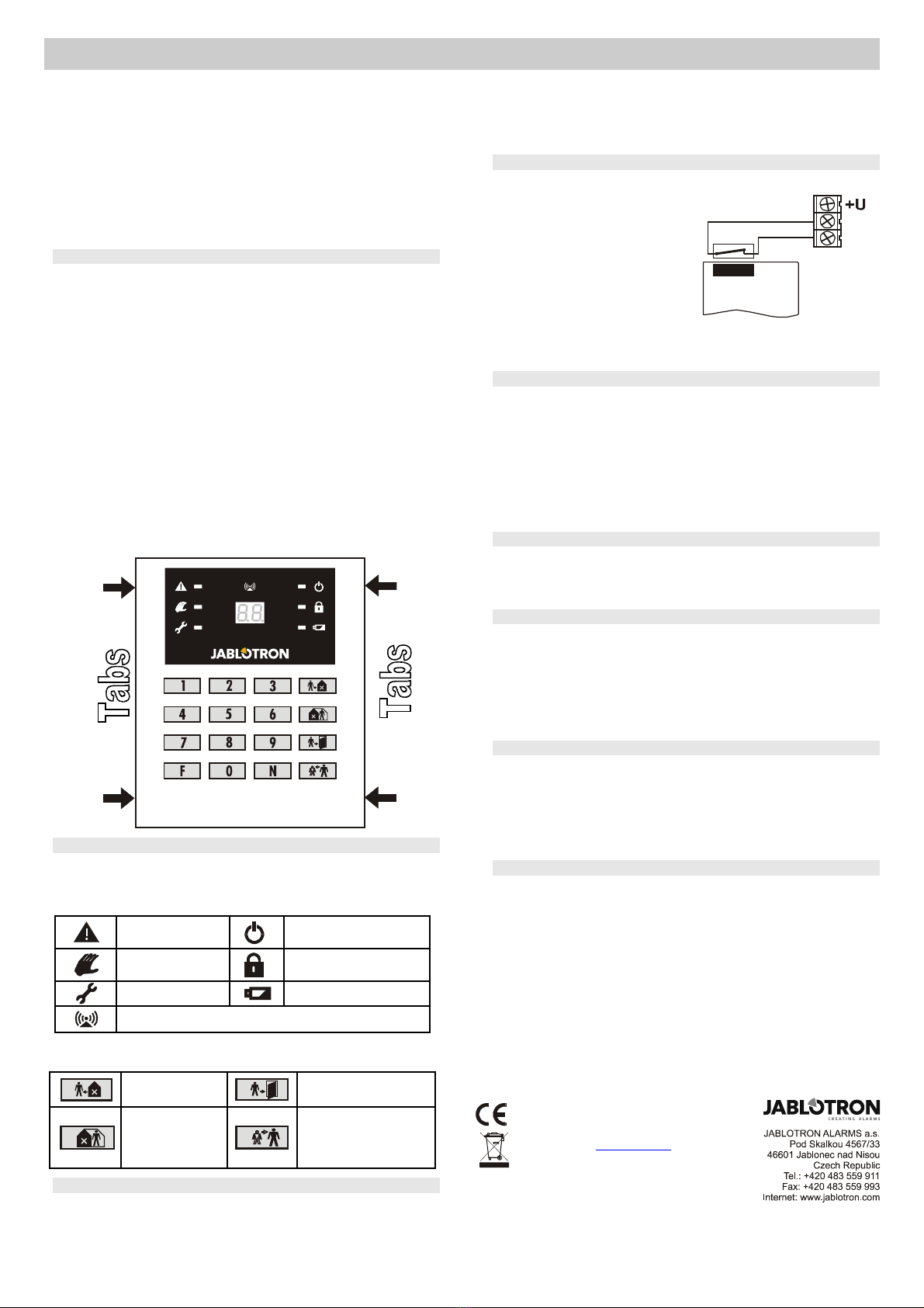
Optional power adapter
If you want the JA-63F keypad to indicate the syste status per anently, it
should be powered by an external power adapter with an output voltage of
12 VDC (stabilized). We reco end use of the Jablotron DE01-12 power
supply.
To install the keypad with an adapter, follow the installation instructions as
above but connect the adapter outlet to the keypad ter inals with the ad-
aptor unpowered ( ake sure the polarity is correct) before inserting the bat-
tery. After enroll ent, plug the adapter into the power socket. Even when us-
ing an adapter a battery should still be present in the keypad so that backup
power supply can be ensured. Do not use rechargeable batteries!
Optional external antenna
External antenna AN-01A can be used in order to increase the operating
radio range.. The external antenna should be connected to the correspond-
ing antenna connector on the JA-63F board (on the right side). Follow the
antenna’s anual instructions when installing the antenna.
Using the keypad for system testing
If the keypad’s housing is released (so that the ta per switch is open) then
the LED indicators and display indicate syste status per anently (sleep
ode is suppressed). This way you can pass through the pre ises with the
keypad in your hands and test all the installed co ponents, seeing an exact
copy of the control panel’s reactions. The keypad should not re ain in this
test ode after you have finished the testing. We reco end using extra
(low cost) batteries for testing. The battery supplied in the package should
not be used until the ti e of syste handover.
Battery testing and replacement
The keypad checks the condition of its batteries auto atically. If it is ne-
cessary to replace the batteries, the keypad will indicate this situation. The
keypad will continue to function as before. If a low battery is indicated, it
should be replaced as soon as possible (within a week).
Before the batteries are replaced, the control panel ust be put into User
ode. Only use high quality alkaline AAA batteries for replace ent. Correct
installation of a battery will be indicated acoustically by a beep.
Specifications
Power supply 6 V – 4x AAA alkaline battery cells
or 12 V DC / 100 mA power a aptor
Battery life time typically 1 year
Number of keypa s in a system max. 8 control evices
Communication ban 433.92 MHz
Communication range max. 80 m (open area, no interference)
Access co es i entical to control panel (1 +14)
Door etector input IN = Normally close
Enclosure IP40
Dimensions 125 x 145 x 30 mm
Degree of protection 2 EN 50131-1
Complies with EN 50131-1 gra e 2
Environmental class II in oor general, -10 to +40 °C
Can be operate accor ing to ERC REC 70-03
The package contains: JA-63F keypa , 4 owels&screws,4 cells AAA
JABLOTRON ALARMS a.s. hereby eclares that the
JA-63F is in compliance with the essential requirements
an other relevant provisions of Directive 1999/5/EC an
2011/65/EU. The original of the conformity assessment
can be foun at www.jablotron.com, Technical Support
section.
Note: Although this pro uct oes not contain any harm-
ful materials we suggest you return the pro uct to the
ealer or irectly to the pro ucer after use. See www.j-
ablotron.com for etails.
JA-63F wireless keypad 2 / 2 MKP51102