jablotron JA-150E User manual

JABLOTRON ALARMS a.s.
Pod Skalkou 4567/33 46601 Jablonec n. Nisou
Czech Republic www.jablotron.com
||
|
JA-150E Wireless keypad
JA-10E BUS keypad 1 / 3 MLU25301
The keypad is a component of the JABLOTRON 100 system used
to control the control panel and display its current status. Using an external
input a door detector can be connected to the keypad.
It is necessary to use this manual in combination with
the JABLOTRON 100 installation and user manuals.
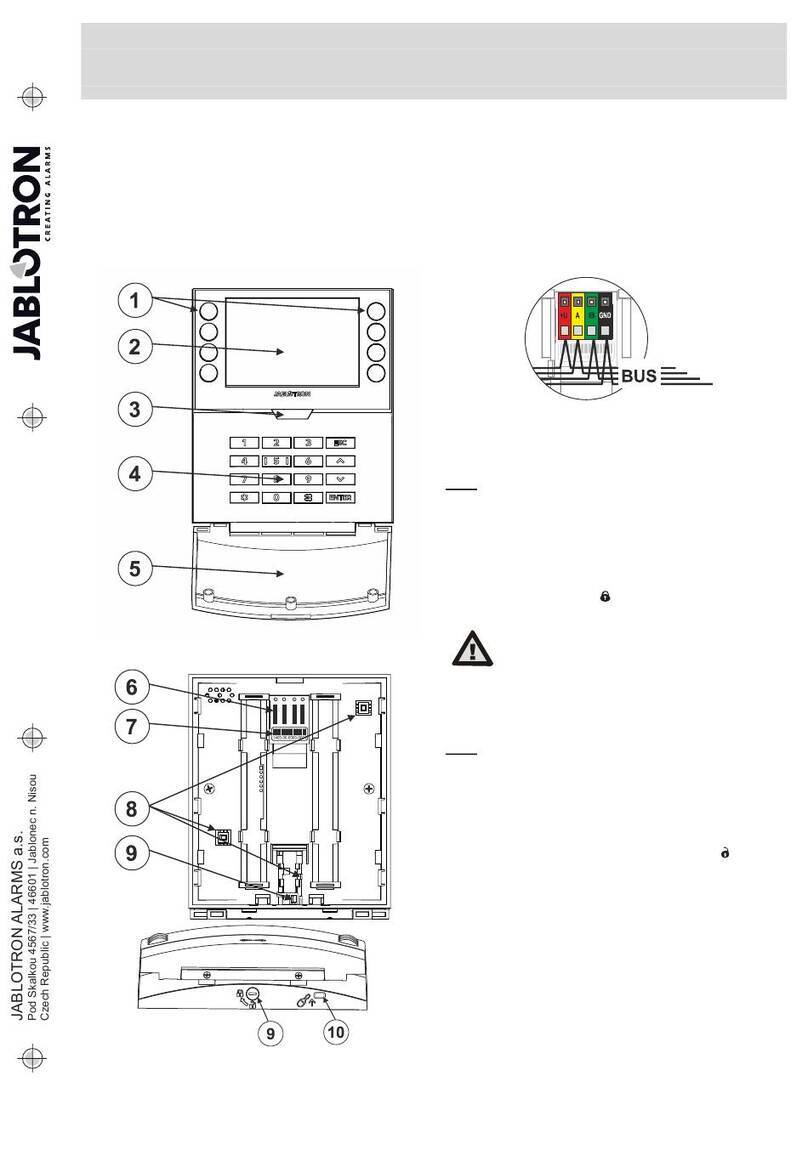
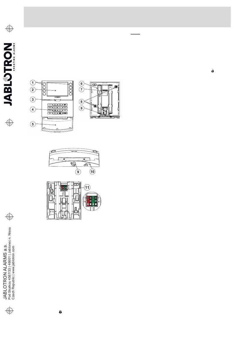
The keypad contains 4 function buttons (5), an LCD display (3),
a system indicator (2), status indicators A, B, C, D (1), a keypad with
an RFID chip card/tag reader (4).
Figure 1: 1 – status indicators A,B,C,D; 2 – system indicator; 3 – LCD
display; 4 – keypad and the RFID reader; 5 – function buttons A, B, C, D;
6 – keypad opening tab; 7 – batteries; 8 – detachable BUS terminals;
9 – tamper contact; 10 – mini USB connector; 11 – production number.
Installation
1. Open the keypad housing by pressing the tab on the bottom (6)
using a screwdriver which will release the keypad from its back part.
2. Screw the back part on a selected place. We recommend using all
four mounting holes and screws to attach the plastic base.
To meet the criteria of EN 50131 grade 2 the plastic base must
be screwed by at least two screws using the mounting hole next
to the tamper contact hole and the mounting hole in the diagonal
corner.
3. Insert two CR123A lithium batteries in the keypad.
4. Insert the keypad back into the back part and lock the bottom tab
using the little screw.
5. Proceed according to the control panel installation manual.
Basic procedure:
a. The JA-111R radio module must be installed in the control
panel. The keypad must be in its communication range.
b. When the device is switched on, the system indicator (2) will
start showing yellow light to indicate that the keypad has not yet
been enrolled to the system.
c. Open the F-Link software, select the required position in the
Devices window, and click on the Enroll button which will open
the enrollment mode.
d. Press the keypad cover to enroll the keypad and the yellow
LED indicator starts flashing (twice with pause) to indicate
Service mode, which may take a few seconds. The enrollment
signal can be sent by inserting the batteries in the keypad
or pressing the tamper contact.
Notes:
Enrollment is also possible by entering its production code (11)
in the F-Link software or using a bar code scanner. All numbers
stated under the bar code must be entered (e.g. 1400-00-0000-
0001).
Installation of a magnetic contact
The keypad supports connection of a door detector. The IN input
reacts to being disconnected from the common GND contact.
The control panel’s reaction to an activated IN input is configurable
in the F-Link SW.
Figure 2: connecting a magnetic contact
Setting the properties
Go to the Devices window in the F-Link software. When you are
at the keypad position, click on the Internal settings option which will
display a dialogue window to configure its settings and function buttons.
Internal settings are separated into 2 basic tabs: Function and Settings.
The Function tab:
Time – Displays the current time in the top-right corner of the display
User text – Enables showing any text, for example the phone number
of an installer company, etc.
Temperature – Displays the temperature measured by one
of the selected thermometers in the bottom-right corner of the keypad
display.
Buttons Function – On the left is a selection of button functions.
On the right is a selection of Sections or PG outputs to which the functions
will be assigned. A function button can be assigned with these functions:
None, Set/Unset, Unset/Partially set, Unset/Partially set/Set, Section
indication, Panic, Fire, Audible panic, Medical Troubles, PG ON/OFF, PG
ON, PG OFF, PG indication, PG indicates inversely, Common function
button.
Authorization – Setting and Unsetting requires user authorization.
When this parameter is disabled the function buttons can be operated
without authorization, however this does not apply to Unsetting a section
which always requires authorization. Both ON and OFF statuses
of PG outputs can be configured to be operated with or without
authorization.
Import – Enables copying settings from other keypads of the same type
and FW version, which have already been enrolled. For example, this can
be utilized when the building has multiple entrances and it is necessary for
all keypads to have identical functions. In addition, this function can also
be used when replacing a faulty keypad with another. The Import button
provides the history of keypad settings on a particular position
of the device.
Section selection – Selection of sections which can be controlled
by authorization (using an RFID chip or a code)
PG selection – Selection of PG outputs which can be controlled
by authorization (using an RFID chip or a code)
The Setting tab:
Acoustic indication of selected sections:
Higher volume – Increased volume of indication (it does not apply
to alarm).
Alarms – Indicates alarm (sounds a siren).
Entrance delay – Continuous sound during the entrance delay.
Exit delay – Slow beeping (1x every second)
Exit delay when partially set – Slow beeping (deactivated by default).
Segment status change –Beeps once when a status is changed.
Function:
Optical indication setting:
1. Indicates permanently – The keypad indicates permanently.
When the mains electricity is disconnected it indicates the same
way as option 3. When mains electricity is restored the keypad
indicates permanently again.
2. Section/PG status change on keypad – The status change
of a section/PG is indicated by a specific function button
and a status indicator. Entrance delay and alarms are indicated
by all function buttons and status indicators.
3. Section/PG status change on segment – The keypad indicates
after a change of the section/PG status, entrance delay and alarm
only by a particular button and a section indicator.
4. Segment status change on keypad – The keypad indicates
after a change of the section/PG status by a particular button and
a section indicator. Entrance delay and alarms are indicated
acoustically only.
5. Entrance delay/Alarms on segment – The keypad indicates
entrance delays and alarms with a function button and a status
indicator. Change of section/PG status is not indicated visually
or acoustically.
6. Wake-up by pressing – The keypad starts to optically and
acoustically indicate after the front cover has been opened and
also when a key or a function button has been pressed.
RFID reader:
In order to save energy we limit the RFID reader to function for
3 seconds after pressing the keypad cover. The RFID reader can be
also completely disabled. This setting applies to wireless keypads
as long as they are permanently supplied by an external power
supply, otherwise their RFID readers will always turn off automatically.
Permanently ON – the RFID reader is always active. This works only
when the Optical indication setting is set to the option number
1 - Indicates permanently.
Activated by pressing – When the keypad is activated the RFID
wakes up for 3 seconds.
Disabled – RFID reader is permanently disabled.

JA-150E Wireless keypad
JA-10E BUS keypad 2 / 3 MLU25301
Activated by pressing or authorization requirement – the keypad
wakes up after pressing a button on a keypad cover
or by an authorization request, for example during the entrance delay.
Wake the keypad by applying an RFID card: Apart from opening
or pressing the keypad cover, the keypad can wake up by applying
an RFID card/tag. It is not recommended to enable this function
if the keypad is surrounded by metal objects and electric wiring.
If this function is enabled, it is necessary to check that the keypad
does not wake up by itself.
Unset a section by authorization only during an entrance delay –
using an access code or an RFID tag will unset a section where
an entrance delay has been triggered (provided the user has access
to the section). This authorization can be used with wireless keypads
only when they declare an entrance delay.
WARNING: This function is not recommended when the control panel
is configured to use a Common section. Unwanted unsetting may
occur to all sections assigned to the Common section or it may even
occur to the whole control panel (when pressing the Unsetting button
is followed by authorization).
Delayed panic – this function triggers a panic alarm (silent or loud)
with an adjustable delay during which the alarm can be cancelled.
Activation and deactivation is done by a function button configured
to Panic or Silent panic functions. The button pressed once triggers
the delay. Press the button the second time to cancel the delay.
When authorization is enabled then it is required for activation and
deactivation. The delay is adjustable from 1 to 255 seconds.
Backlight intensity
Indicators – Backlight intensity of indicators.
Function buttons – Backlight intensity of the function buttons.
Keypad – Backlight intensity of the keypad.
Display –Backlight intensity of the LCD display.
Contrast – LCD display contrast.
A keypad configuration which complies with
certification requirements must be selected
from the list of System profiles in the
Parameters tab of the F-Link SW.
Automatic stand-by mode
When the keypad is battery supplied it preserves energy by turning
off the system indication and the display after keys on the keypad
haven’t been pressed within 10 second or when the keypad cover
is closed. However the keypad still maintains communication with
the control panel and will for example signal entrance delay.
The keypad will be completely active when the keypad cover
is opened, pressed or by applying an RFID card (provided this
function has been activated in the Settings).
Alternative power supply
The keypad can be supplied from an external power supply
with 12 V DC connected in +U and GND terminals. You can use
the DE06-12 Power adaptor suitable for concealed installation.
When the keypad is supplied externally it will communicate with
the control panel permanently and it will indicate system statuses
according to the selected parameters in Internal settings
in the Devices tab. If the alternative power supply is used keep
the batteries in the detector, they will provide back up in case
the power supply is disconnected. Batteries inserted in the detector
cannot be recharged by the external power supply.
Changing the batteries
The keypad automatically checks its own battery status. When
the batteries are close to being depleted, it will inform the control
panel that the batteries need to be replaced. They should be replaced
within two weeks after the message appears. The control panel must
be switched into Service mode before removing the keypad from
the back part otherwise (otherwise a tamper alarm will be triggered).
Note: In order to make sure the keypad works correctly,
we recommend using batteries supplied by the distributor or other
quality brand lithium batteries.
Optical indication
System indicator:
Continuous green light - Normal operation. Sections controlled
by the keypad are OK, no faults.
Continuous yellow light - Normal operation, reported faults
in some of the controlled sections. You can get more detailed
information via the LCD keypad menu after user authorization
depending on the user access rights.
Optical indication followed by a rotating Jablotron logo on the LCD
keypad represents a radio communication fault between the control
panel and the keypad
Continuous red light – The keypad is in BOOT mode, used while
upgrading firmware.
Flashes green (2Hz) – Ongoing authorization during which the user
can change the statuses of the function buttons or browse the keypad
menu. Authorization times out after 8 seconds from the last time any
of the buttons had been pressed or it can be cancelled by pressing
ESC.
Flashes yellow (8Hz) - Unsuccessful setting warning indication
Flashes red (8Hz) - Indication of a currently triggered alarm in one
of the sections controlled by the given keypad. The type of alarm,
name of the section where an alarm has been triggered and
the source of the triggered alarm are visible on the LCD keypad.
Flashes alternately red/yellow - Triggered alarm with an active fault
indication.
Flashes alternately green/red – Ongoing authorization with an alarm
memory.
Flashes alternately green/yellow – Ongoing authorization with
an active fault indication.
Flashes yellow 2x every 2 seconds - Programming / Service mode.
All control segment indication is disabled, function keys along with the
keypad menu are unavailable for users and the Administrator.
The keypad menu is only available for a service technician unless
a PC is connected to the control panel.
Flashes red 2x every 2 seconds - Alarm memory indication.
Flashes yellow 1x every 2 seconds - Fault indication on a keypad
which is in sleep mode (only valid for the EN50131-1 and Incert
profile).
Flashes red 1x every 2 seconds - Alarm memory indication
on a keypad which is in sleep mode (only valid for the EN50131-1 and
Incert profile).
No indication – The keypad is in sleep mode.
Function buttons and status indicators – the status of the function
buttons is simultaneously indicated by the status indicators A, B, C, D.
Continuous green light - Section status is Unset or a PG output
is OFF.
Flashes green (4Hz) – Ongoing entrance delay. The control panel
waits to be Unset.
Continuous yellow light - Section status is Partially set.
Continuous red light - Section status is Set or a PG output is ON.
Flashes yellow (4Hz) - The control panel expects authorization when
partially set or it reports a fault during partial setting.
Flashes yellow (8Hz) - Unsuccessful setting warning indication.
Flashes red (4Hz) – The control panel waits for authorization during
setting or it reports a problem during setting.
Flashes red (8Hz) - Alarm memory indication. It is indicated until
it is cancelled.
No light - Service mode or a blocked section after an alarm (after
blocking and cancelling alarm memory indication).
Acoustic indication
It can be set regardless of the keypad’s optical indication and sleep
mode. The keypad can indicate entrance/exit delay or alarm.
During valid authorization (by a user code or RFID card), the acoustic
indication of exit delays is suppressed. By pressing the indication
button the keypad is muted permanently. Entrance delay and alarm
are indicated until their time expires, unless the activation button
is pressed.
Keypad FW update
The keypad supports wireless FW updating which is done
in Service mode via the F-Link software.
1. Select Control panel
Æ
Æ
Firmware update. You’ll see
JA-150E in the dialog window. If F-Link contains newer
firmware than the one in the keypad then it will be automatically
offered.
2. Pressing the OK button will perform update of selected devices.
3. After the FW update is finished, check the keypad’s internal
settings in the Internal settings in the Devices tab.
4. Check the keypad’s functionality.
Note:
The mini USB connector (10) is used to update the firmware
by connecting the keypad with a computer via a mini USB cable.
Use this method when wireless update fails.
JABLOTRON ALARMS a.s.
Pod Skalkou 4567/33 46601 Jablonec n. Nisou
Czech Republic www.jablotron.com
||
|
JA-150E Wireless keypad
JA-10E BUS keypad 3 / 3 MLU25301
Technical specifications
Power 2 x Lithium battery type CR123A
Please note: Batteries are not included
Typical battery lifetime 1-2 years according to settings
External supply input power 0,5 W
Communication band 868.1 MHz, JA-100 protocol
Communication range approx. 200 m (open area)
RFID frequency 125 kHz
Size 120x130x30 mm
Weight 215 g
Classification Grade 2/environmental class II/ACE type B
(if selected in the F-Link SW)
- According to EN 50131-1, EN 50131-3, EN 50131-5-3, EN 50131-6, T 031
- Operational environment indoor general (according to EN 50131-1)
- Operating temperature range -10 to +40 °C
- Average operational humidity 75% RH
- Certification body Trezor Test
- Power supply Type C according to EN 50131-6
- Low battery voltage detection 5 V
Complies with ETSI 300 220-2, ETSI EN 300 330-2,
EN 50130-4, EN 55032, EN 60950-1
Can be operated according to ERC REC 70-03
JABLOTRON ALARMS a.s. hereby declares that the JA-150E
is in a compliance with the relevant European Union
harmonisation legislation: Directives No: 2014/53/EU,
2014/35/EU, 2014/30/EU, 2011/65/EU. The original of the
conformity assessment can be found at www.jablotron.com -
Section Downloads.
Note: Although this product does not contain any harmful
materials we suggest you return the product to the dealer
or directly to the producer after use. For more detailed
information visit www.jablotron.com
Other jablotron Keypad manuals

jablotron
jablotron JA-80E User manual

jablotron
jablotron JA-155E User manual

jablotron
jablotron JA-60F User manual

jablotron
jablotron JA-115E User manual

jablotron
jablotron JA-10E User manual

jablotron
jablotron KB-1051 User manual

jablotron
jablotron KB-2051 User manual

jablotron
jablotron JA-15E User manual

jablotron
jablotron JA-114E User manual

jablotron
jablotron 100 User manual
Popular Keypad manuals by other brands

Nuvo
Nuvo NV-P20 Series instruction sheet

International Electronics
International Electronics 212iLM Mullion installation manual

Ketra
Ketra X 2 installation guide

Axema
Axema VAKA-CALL Master 4G manual

Chamberlain
Chamberlain LiftMaster Professional WGB315 Security+ user guide

VAT
VAT videofied XMB611 Installation datasheet