Jack JK-T781E User manual

JK-T781E series

technical parameters and models
Model JK-T781E JK-T782E JK-T783E JK-T781EK
Purpos (Textile, chemical fiber fabric )buttonhole`s
sewing lock
Knitting
Buttonhole length 22mm 33mm 40mm 22mm
Stitch width 2.5~4mm 2.5~5mm 2.5~5mm 2.5~4mm
Cutter length 6.4~19mm
(1/4”~3/4”)
6.4~25.4mm
(1/4”~1”)
6.4~31.7mm
(1/4”~1 1/4”)
6.4~19mm
(1/4”~3/4”)
Speed 100~3600rpm/min
Needle stroke 34.6mm
Presser foot height 10mm
Needle DP×5(#11~#14)
Refueling mode Automatic oiling
Sewing thickness 4mm
Needle count Factory equipped with 4 unitsG(225,83) J(190,100) L(170,110)
N(152,123)
Market has 8 units 54针~345针

First way:see the no. of 2 in the first picture, put the ruler like this between the Needle
plate and needle bar,move the position of needle bar until the distance between needle
bar and the ruler is 0. Adjust the hook to make the tip of the hook from the upper end of
the pinhole 1.6 ~ 1.8mm, tighten the screw of Rotary hooks to make that the distance
between two Tips of the hook is about 0.05 mm.
ruler, this part 14.2mm
1.2 adjust needle and hook
1.6~1.8mm
0.05mm
requirement for catching
thread

2.1、adjust the needle bar height
Second way:(observe the hook),Install the needle to make the needle in the middle
of the pinhole, move the needle bar to the lowest point, observe and make the upper
edge of the pinhole not exceed the needle plate.
needle
plate
lowest
point,of the
needle
Front panel
of neele
plate
the middle
of the
pinhole

Second way: 1、Turn the handle,until the the pallet moves to the right baseline,
Turn the handwheel until the needle moves to the right baseline,during the period of
returning of the needle bar, adjust the Rotary tip util hooking above the pinhole,at
the the lowest plat.
2、Adjust the rotary hook positioning screw, util hook tip close to the needle, but not
hit the needle (zero distance).3、pls. note when the hook catchs thread, the rotary
hook needle plate must be close to the needle, but not squeezed(zero distance).
2.2、adjust needle and hook
the needle
moves to the
right baseline
hooking above
the pinhole
hook tip close
to the needle
requirement for
catching thread

3.0、adjust buttonhole width and stitching reference position
The movement of the needle is based on the right side of the needle swing. When
adjusting, please follow the following steps:
1、Baseline width adjustment: Turn screw 1 and align the baseline pointer to the desired
scale on the scale plate.2、Reinforce sewing width adjustment:Tighten screw 2 to align the
reinforcement pointer to the baseline pointer.3、Right baseline position: twist screw 3, adjust the
cutter to cut the screws when the right baseline is not cut.4、Left position of the baseline: When
screwing the screw 4 so that the blade does not have a left baseline, tighten the screw.
screw 1Baseline
pointer
Scale
plate
screw 2
Reinforce
pointer
screw 4
screw 3

4.0 adjust position of feeding control panel when work finished
◆If the control plate position is not correct, whenever you change the sewing size, the
knife will malfunction, the position of the presser foot will change, resulting in broken
needle, broken thread.
◆adjustment method: when stopping,make the scale line of plate align the middle
position of the roller pin screw. If the position is not correct, move the part A of the right
pic. to reaze this .
大盘刻线
control plate
Scale line of plate

Standard:This adjustment is same as 781D serie.
781E Machine
mode and Number Comparison
table
Mode
781E
782E
783E
781EK
Number
on dial
1/2
1
5/4
1/2
:
Method:
1. Pull out the part, put up the canning.
2. Loose the screw, let the pointer front to the number you need. (The number
should be same as length of cutter) Then tighten the screw。
18.0:Adjustment of the button hole length
Feeding Crank
Loose screw
Pointer
Notice:After change the number on dial, then
should change the presser foot similar as the
length of button hole.

Adjustment stardard: the distance between fixed knife and needle plate hole is 0.3-0.5mm.
Adjustment influence: if the distance between the fixed knife and the needle plate hole is too
close, the thread breakage will happen when you sew.
Adjustment method:
1.Lose the fixed knife fasten screw.
2. Adjust fixed knife, make the distance
between the fixed knife and the needle
plate hole to 0.3-0.5mm and then
fasten the screw.
19.0:Adjustment of the position of lower line fixed knife
fixed knife fasten screw
fixed
knife

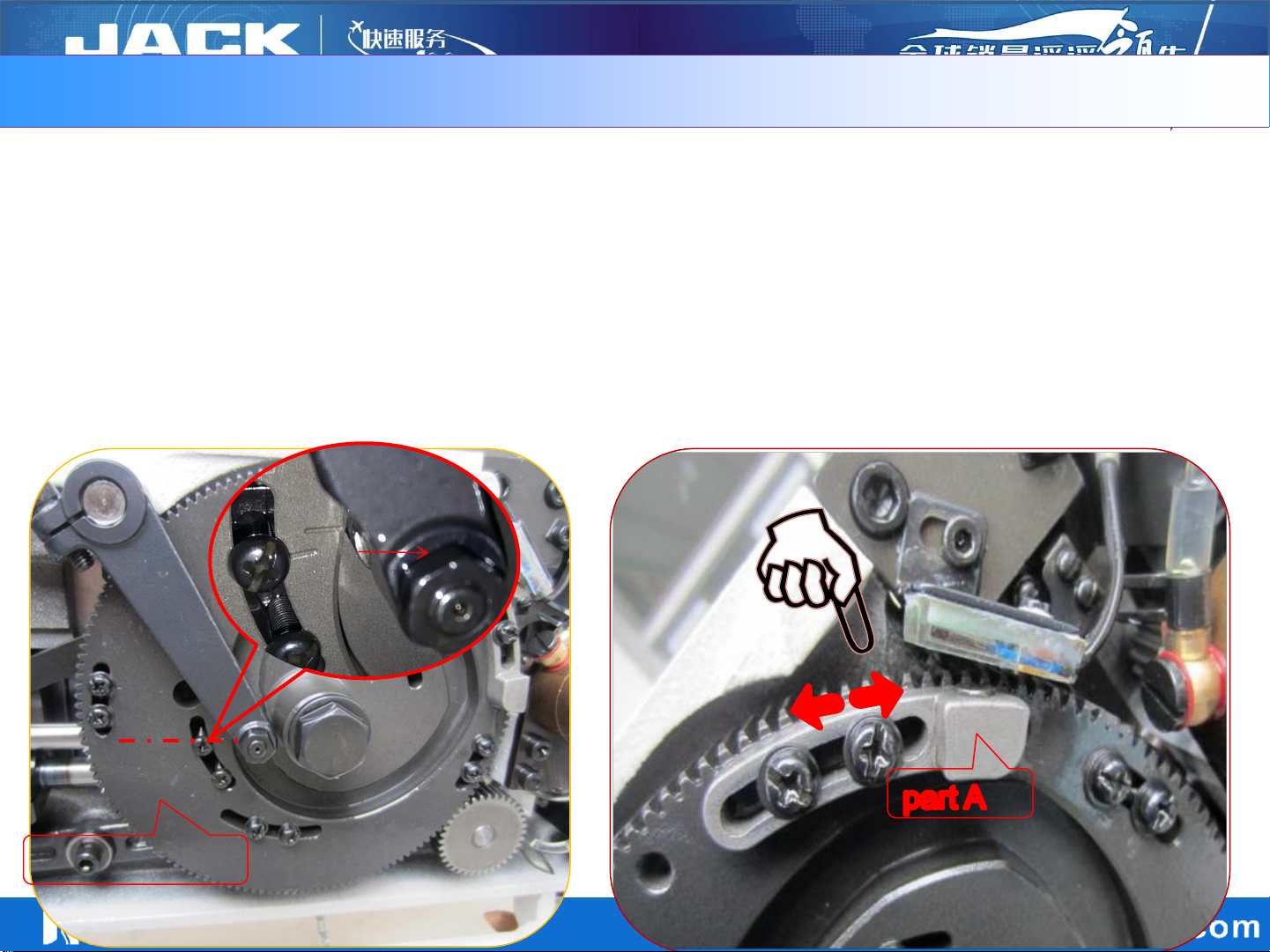
Adjustment standard: When the machine is in the parked position (the presser foot is in the
decentralized state), the motor will automatically find the zero position, so that the mechanical lock
between the starting plate and the movement pin left 3mm gap.
29.0:The sensor chip of automatic foot-lift position adjustment
3mm Gap
Sports pin
Sensor chip
Sensor
The sensor chip is aligned with up-side of the stamp mark of sensor
Stamp mark
Larger
Smaller
Adjustment methods:
1. Loosen the setscrews and adjust the sensor chip up and down relative to the sensor. (Up to adjust sensor
chip, the gap becomes larger after booting to find the zero position, down to adjust the gap smaller.)
2.Re-boot to find zero position, verify the mechanical lock between the starting plate and the
movement pin left 3mm gap.

31.0:Adjustment and functions of feeding sensor
◆The main function of feeding sensor is:prevent foot lifting during sewing, the sensor lamp
goes out when entering the sewing state,press , can not lift the foot,when stop sewing,
the sensor lamp lights up and presses presser , lift the presser foot
◆Easy to adjust the presser foot up and down during maintain
Adjustment method;Loosen the set screws, adjust the sensor up and down, make sure
that the distance between sensor and sensor magnet is about 1.5mm, and could be lit up
when stop
set screws
set screw
sensor magnet

三、Parameters and fault codes
1、Operation button
Enter and determine the
stored content value
Enter the parameter content value,
any
changes of
the value, need to press the
key to save confirmation.
Enter the parameter area
function key
1. In normal boot mode, press the key
to enter the user parameter mode
2. Press and hold the key to enter the
technician parameter mode
Set the value increment /
parameter increment
1. In the parameter selection area,
as the
key to increase
the parameter
2.
In the parameter contents area, as the
key
to increase the value
Set the value decrement /
parameter decrement
1. In the parameter selection area,
as the
key to decrease
the parameter
2.
In the parameter contents area, as the
key
to decrease the value

2、LED display script and actual script comparison table
3、Display mode of the LCD screen
Digital script part:
Actual value:
LCD:
English script part:
English alphabet:
LCD:
English alphabet:
LCD:
English alphabet:
LCD:

Press the up and
down key and at the
same time boot the
machine up, it will
show P11.
Press F key and reboot
Press enter key
to save it
4、Factory reset

5、Enter user mode and modify & save(1-10)
In normal case,
press F to get into
user parameter mode.
Press up and
down key to change
parameter items.
Press enter key to
get the value of this
parameter.
Press up and down
key to modify the
parameter value.
Press F key to get out
of this mode.
Press enter key to
save the value

6、Enter technician mode*(11-25)
Press F key
and at the
same time boot
the machine up
Press up and
down key to change
parameter items.
Press enter key to
get the value of this
parameter.
Press up and down
key to modify the
parameter value.
Press enter key to
save the value
Press F key to get out
of this mode.

7、System officer mode-limited to item(26-27)
Press F and
enter key
and at the
same time
boot the
machine up
Press up key to
find
P26 (speed
limit) and the
press ENTER to
get the value.
Press F key to
get out of this
mode.
Press up and down
key to modify the
parameter value
and then press
enter to save.

8、Manual up positioning adjustment
Press the up
and down key
and at the
same time
boot the
machine up
Move the hand
wheel to adjust
and press
enter key to
save.
Press up key
to find
P27 and the
press ENTER to
get into it.
Press F key to
get out of this
mode.

9、user parameters
item description range Initial
value note
P01 Max speed(rpm)10~360 300 Sewing speed(actual speed=display number
*10)
P02 Start sewing speed
(rpm)20~360 130 Start sewing speed(actual speed=display
number*10)for 781E, it doesn’t work
P03 Cutter movement
speed 10- 100 55 The rotation of head during the cutting(actual
speed=display number*10)
P04 Speed limit for 1st
stitch 10~360 80 (actual speed=display number*10)
P05 Speed limit for 2nd
stitch 10~360 80 (actual speed=display number*10)
P06 Speed limit for 3rd
stitch 10~360 200 (actual speed=display number*10)
P07 Speed limit for 4th
stitch 10~360 250 (actual speed=display number*10)
P08 Speed limit for 5th
stitch(reserved)10~360 200 (actual speed=display number*10)
P09 Presser foot
protection time(s)1 - 120 8 Presser foot will drop after exceeding
the continual lifting time set. (Only for
781D)
P10 Stitches required
during the cutting.
0 - 5 3 Stitches required during the cutting.
Coordinated with cutter speed.

item description range Initial
value note
P16 Protected stitches 1 - 990 400 How many stitched protected if the big board senses
nothing
P17
Find the up position
automatically after
booting
0 - 1 1 1:Find the up position automatically after booting
0:function closed
P18 Up positioning
adjustment 40 - 180 110 Up positioning adjustment, value decreases means
stop in advance by 2mm and vice versa
P19 Test working time 1 - 250 20 In C test, setting working time.
P20 Test stop time 1 - 250 20 In C test, setting stop time.
P21 A test 0 - 1 0 In A test, continual working test with speed P01
P22 B test 0 - 1 0 In B test, full functional test with speed P01
P23 C test 0 - 1 0 In C test, no positioning working with speed P01
P24 Head protection switch 0 - 1 1 0:function closed
1:function
P25 Mechanical lock
protection switch 0 - 1 1 0:function closed
1:function
P26 Speed limit 10~360 300 Speed limit(actual speed=display number*10)
P28 The highest presser foot
height 0 - 400 250 Adjust the stepper motor angle when it’s in highest
presser foot height
P29 Presser middle position 0 - 400 00
Adjust the stepper motor angle when it’s in presser
middle position
Other manuals for JK-T781E
1
This manual suits for next models
4
Table of contents
Other Jack Sewing Machine manuals

Jack
Jack H2 Series Specification sheet

Jack
Jack JK-58420J Product guide

Jack
Jack J?796-5-36 User manual

Jack
Jack k4 Series Product guide

Jack
Jack JK-2284 Product guide

Jack
Jack JK-1000Q6 User manual

Jack
Jack JK-8995 User manual

Jack
Jack A4 User manual

Jack
Jack JK-T1377E User manual

Jack
Jack ZB-A2S User manual