manuals.online logo
Brands
  1. Home
  2. •
  3. Brands
  4. •
  5. Jamara
  6. •
  7. Motorized Toy Car
  8. •
  9. Jamara Ultra BL 8 2,4 GHz User manual

Jamara Ultra BL 8 2,4 GHz User manual

Ultra BL 8 2,4 GHz
No. 059730 BL Lipo
33/21
Frequency bands: 2.4Ghz Frequency range: 2405,5 MHz - 2475,0 MHz EIRP: 49,09 mW (max. power transmitted)
IT - Istruzioni di montaggio
GB - Instruction
Konformitätserklärung
Con la presente JAMARA e.K. dichiara che il prodotto “Ultra BL8 2,4 GHz, No. 059730“
è conforme alla Direttiva 2014/35/UE, 2014/53/UE e 2011/65/UE.
Il testo integrale della dichiarazione di conformità UE è disponibile al seguente
indirizzo Internet www.jamara-shop.com/Conformity
Certifi cate of Conformity
Hereby JAMARA e.K. declares that the products “Ultra BL8 2,4 GHz, No. 059730“ comply with
Directives 2014/35/EU, 2014/53/EU and 2011/65/EU.
The full text of the EU Declaration of Conformity is available at the following Internet address:
www.jamara-shop.com/Conformity
IT - Informazioni generali
JAMARA e.K. non e´responsabile per danni, sostenute al prodotto stesso o attraverso questo, dovuti
ad una gestione non corretta del articolo. Solo il cliente si assume la piena responsabilità per la
manutenzione e l´utilizzo corretto dello stesso; questo include il montaggio, la ricarica, l´utilizzo, 
no alla scelta della aerea di applicazione. Si prega di notare e rispettare le istruzioni d´uso, questi
contengono informazioni e avvertimenti molto importanti.
GB - General information
Jamara e.K. is not liable for any damage caused to the product itself or through this, provided this
is due to improper operation or handling errors. The Customer alone bears the full responsibility for
the proper use and handling, including without limitation, the assembly, the charging process, the
use and choice of the operation area. Please refer to the operating and user instructions, it contains
important information and warnings.
Attenzione!
Prima dell‘uso: Accendete prima la trasmittente e poi il modello.
Dopo l‘uso: Spegnere prima il modello e poi la trasmittente.
●Non utilizzare il suo modello fuori della distanzia di vista. Sia la visibilità come la portata
massima del vostro modello dipendono da molti fattori, come il tempo, disturbo di
frequenza e il luogo di utilizzo. Eseguire un test prima di ogni utilizzo del modello con
una seconda persona che tiene fi ssato il modello. Con questa procedura potete testare
come reagisce il modello durante la perdita del segnale causato per esempio da una
batterie scarica oppure la radio spenta.
Attention!
Before operating: Switch the transmitter on fi rst then the model.
When fi nished: First switch off the model then the transmitter.
●Never operate your model beyond sight. Both the maximum visibility as well as the max.
range of your model will depend on many factors such as weather, location and
interfering frequencies. Therefore, before each use perform a range test with a second
person securely holding the model and also check how the model reacts if there is a
signal failure e.g. when empty transmitter batteries are installed.
Prima di avviare il modello, leggere attentamente tutte le istruzioni per l’uso.
Attenzione! Leggere completamente le avvertenze / istruzioni di sicurezza, questi
sono per la vostra sicurezza può prevenire incidenti / infortuni.
Read the complete instructions and security instructions carefully before using the model.
Caution! Please fully and carefully read warnings/ safety instructions. These are for
our own security and can avoid accidents/injuries.
Questo modello non é un giocattolo!
Sconsiliato per persone inferiori di 14 anni.
Attenzione: Tenere sempre fuori dalla portata dei bambini.
Contiene piccoli pezzi che possono essere ingeriti.
RISCHIO DI SOFFOCAMENTO!
Non adatto a bambini di età inferiore a 36 mesi.
This model is not a toy!
Not suitable for people under 14 year.
Warning: Keep away necessarily from children.
Contains small parts which can be swallowed.
RISK OF SUFFOCATION!
Not suitable for children under 36 months.
Accessori consigliati + Strumenti Recommended Tool + Equipment
Questo prodotto è un articolo di modellismo. Ciò signi ca che il veicolo deve essere sempre sotto-
posto a manutenzione (controllare eventuali danni, controllare i collegamenti a vite, pulire ecc...).
Le parti soggette ad usura come l‘ingranaggio principale, il pignone del motore, bicchierino ecc.
si consumano nel tempo e devono pertanto essere sostituite. Non è sempre possibile evitare gli
incidenti, pertanto è necessario riparare o sostituire anche i danni causati dagli incidenti. Le parti
usurate o difettose a causa di urti o manutenzione insuf ciente non sono coperte da garanzia, i
costi e le riparazioni sono a carico dell‘acquirente stesso.
This product is a model building article. This means that the vehicle must always be serviced
(check for damage, check screw connections, clean etc...). Wear parts such as the main gear,
motor pinion, bone socket, etc. will wear out over time and must therefore be replaced. Crashes
cannot always be avoided, so crash damage must also be repaired or replaced. Wear parts or
defective parts due to crashes or insuf cient maintenance are not covered by warranty, costs and
repairs must be covered by the buyer himself.
No. 190065
Misuratore convergenza
Camber adjusting Tool
No. 15 3059
X-Peak 80 V2
Caricatore
Charger
No. 232060
Power Tape silicone
Doublesided power tape
No. 232423 medium
Lacca protezione
Nut lock
No. 505401 piccolo/small
Graffette per carrozzeria
Body clips
No. 059273 1:10
Graffette per carrozzeria
Body clips
No. 232423 medium
Protezione Vite
Nut lock
No. 281730
Forbici per lexcarrozzeria
Lexan scissors
2
1
2
6
5
34
1 2
1 2 3
4
IT- Avete acquistato un modello RTR. Ciò signi ca che il veicolo è in gran parte pronto
per l‘uso immediato. Tuttavia, è essenziale controllare che il modello non presenti
possibili danni meccanici o elettrici o difetti prima e dopo ogni utilizzo. È inoltre
necessario veri care la libertà di movimento di tutti gli elementi mobili e la tenuta
dei collegamenti a vite.
GB - You have purchased a RTR model, which means it should be ready for immediate use after
charging all batteries. You need to check the car, electronics and all plastic parts after each use to
make sure no parts are damaged. Also all the moving parts must be checked for their clearance,
bolts and screws that they are tight.
IT - Lieferumfang
1. Modello
2. Telecomando
3. Antenna
4. Connettore di collegamento
5. Batteria
6. Caricatore
Accessori:
• Telecomando: 4 x AA 1,5V,
Nr. 14 0267 (4 pezzi)
Dati tecnici:
• Dimensioni:
~ 515 x 275 x 205 mm
• Peso: ~ 2360 g
• Batteria: LiPo 7,4 V 5000mAh
• Motor: 420W, 3000KV
Le informazioni non sono ga-
rantite. Ci riserviamo il diritto di
apportare modi che tecniche e
la possibile presenza di errori.
GB - Box contents
1. Model
2. Transmitter
3. Antennas
4. Binding Plug
5. Battery
6. Charger
Accessories:
• Transmitter: 4 x AA 1,5V,
No. 14 0267 (4 pieces)
Technical data:
• Dimensions:
~ 515 x 275 x 205 mm
• Weight: ~ 2360 g
• Battery: LiPo 7,4V, 5000 mAh
• Motor: 420W, 3000KV
No responsibility is taken for the
correctness of this information.
Subject to change without prior
notice.
Errors and omissions excepted.
Note importanti sull‘idoneità della batteria:
Assicurarsi di utilizzare solo batterie ai Polimeri di Litio con connettore XH balancer. Solo queste
possono essere utilizzate con il caricatore. Altri collegamenti e tipi di batterie non possono essere
utilizzati (si può veri care il rischio di incendio dovuto all‘inversione di polarità o al sovraccarico).
Si prega di contattare il produttore della vostra batteria per sapere se la vostra batteria è adatta. Uti-
lizzare solo batterie LiPo con una capacità di almeno 1600mAh (altrimenti c‘è il rischio di incendio
a causa della corrente di carica eccessiva). Se si utilizzano batterie con una capacità inferiore a
1600mAh, le batterie devono essere approvate per una corrente di carica di 1600mA (carica rapida).
Si prega di chiedere al produttore della vostra batteria se la vostra batteria soddisfa questi requisiti.
È possibile collegare solo una singola batteria alla volta al caricatore. Caricare 2 batterie
allo stesso tempo NON è permesso e causerà danni alla batteria o al caricatore (pericolo di
incendio).
Important notes on the suitability of the battery:
Make sure to use only lithium polymer batteries with XH balancer connector. Only these may
be used with the charger. Other connections and battery types must not be used ( re hazard due to
reverse polarity or overcharging may result).
Please contact the manufacturer of your battery to  nd out whether your battery is suitable. Only
LiPo batteries with a capacity of at least 1600mAh must be used (otherwise there is a risk of
 re due to excessive charging current). If you use batteries with a capacity below 1600mAh, the
batteries must be approved for a charging current of 1600mA (Speedcharging). Please ask the
manufacturer of your battery if your battery meets these requirements.
You may only connect one single battery to the charger at a time. Charging 2 batteries at
the same time is NOT allowed and will cause damage to the battery or charger (fi re hazard).
IT
1. Ingresso 100 - 240 V
2. Attacchi di bolanciatore 2 cella
3. Attacchi di bolanciatore 3 cella
(Non richiesto per questo modello)
4. LED di stato
GB
Technical data:
1. Power Slot 100 - 240 V
2. 2S Balancer
3. 3S Balancer
(Not required for this model)
4. Status LEDs
LiPo Processo di ricarica LiPo Charging process
LiPo Processo di ricarica
1. Inserire il cavo di alimentazione del caricabatterie in una presa adatta. I LED si illuminano di
verde e indicano che la batteria è pronta per la ricarica
2. Ora collega la batteria vuota al caricatore. Batterie 2S da 7,4V al connettore a 3 poli o 11,1V
batterie 3S al connettore a 4 poli. Non usare la forza e fare attenzione a non invertire la polarità.
I LED diventeranno rossi dopo pochi secondi, indicando che le celle della batteria si stanno
caricando.
Attenzione!
Quando si collega una batteria 2S, solo i primi 2 LED (Cell1-2) diventano rossi, il LED 3
(Cell 3) rimane verde. Quando si collega una batteria 3S, tutti i LED (Cell1-3) diventano
rossi.
Non appena una cella della batteria è completamente carica, il LED corrispondente diventa
verde. Poiché le celle sono caricate individualmente, è possibile che una cella sia
completamente carica prima delle altre, a seconda dello stato della batteria. Lasciare sempre la
batteria sul caricatore  no a quando tutte le celle collegate sono completamente cariche (verde)
per permettere al caricatore di bilanciare la batteria.
Charging a battery
1. Plug the power cord of the charger into a suitable socket. The LEDS light up green and indicate
that the charger is ready for charging.
2. Now connect the empty battery to the charger. 7.4V 2S batteries to the 3 pin connector or 11.1V
3S batteries to the 4 pin connector. Do not use force and pay attention to reverse polarity. The
LEDs change to red after a few seconds and indicate that the battery cells are charging.
Attention:
When connecting a 2S battery, only the fi rst 2 LEDs (Cell1-2) change to red, LED 3 (Cell 3)
will remain green. When 3S batteries are connected, all LEDs are red (Cell1-3).
As soon as a the battery cell is full, the corresponding LED changes to green. Because the cells
are charged individually in a balanced way, it is possible that one cell is fully charged earlier than
the others. Always leave the battery on the charger until all connected cells are fully charged
(green) to allow the charger to balance your battery
4x AA
ON/OFF
1
IT - Riconoscimento di una batteria carica.
Quando si collega una batteria carica al caricatore, i LED diventeranno rossi per alcuni secondi e poi
torneranno verdi. Questo signi ca che la batteria è già completamente carica.
Riconoscimento di una batteria difettosa.
Se i LED rimangono verdi quando si collega una batteria vuota, c‘è un difetto nella batteria (difetto
della cella o scarica profonda). In questo caso, scollegare immediatamente la batteria dal caricatore
e utilizzare un‘altra batteria.
GB - Detecting a full battery.
When you connect a full battery to the charger, the LEDs will turn red for a few seconds and then
turn green again. This means that the battery is already fully charged.
Detecting a defective battery.
If the LEDs remain green when an empty battery is connected, there is a defect in the battery (cell
defect or deep discharge). In this case, immediately disconnect the battery from the charger and
use another battery.
Montaggio delle batterie nel trasmettitore
Inserire 4 batterie AA nella trasmittente.
Inserting batteries into the transmitter
Put 4 AA Batteries into the Transmitter
IT - Informazioni relative alle pile:
Le batterie non ricaricabili non devono essere caricate!
Non aprire!
Non gettare nel fuoco!
Non usare contemporaneamente pile nuove e pile usate!
Non usare contemporaneamente pile alcaline, standard (zinco-carbone) e ricaricabili!
Le batterie ricaricabili devono essere rimosse dal giocattolo!
Le batterie ricaricabili possono essere ricaricate solo sotto la supervisione di un adulto!
I morsetti di collegamento don devono essere cortocircuitati!
GB - Battery warning:
Non-rechargeable batteries are not to be recharged!
Do not open!
Do not dispose of in  re!
Do not mix old and new batteries!
Do not mix alkaline batteries, standard (carbon-zinc) or rechargeable batteries!
Rechargeable batteries are to be removed from the toy before being charged!
Rechargeable batteries are only to be charged under adult supervision!
The supply terminals are not to be short-circuited!
Regolatore
ESC
Batteria
Battery
● Mettete la batteria nel vano della batteria, a bordo del veicolo. Fare attenzione che la batteria
sia correttamente fissata con i 2 clip in dotazione e che la batteria non abbia un gioco
eccessivo nel vano appropriato.
● Ora collegare la batteria con il regolatore del modello. Se la spina del regolatore e la spina
della batteria non corrispondono, un cavo adattatore è incluso con il modello.
● Leggere il capitolo sulla trasmittente. Accendere la trasmittente e assicurarsi che i trim siano
in posizione neutrale
● Tenere il modello in aria per il caso che il motore si metta a girare a tutto gas.
● Ora accendere il regolatore di velocità tramite l`interruttore ON / OFF.
● Vi incoraggio ad attivare il ricevitore integrato in unità fail-safe.
Al momento della consegna è spento.
● Se questa è la tua prima auto rc, si consiglia di guidare su una pista piccola per familiarizzare
con il controllo del veicolo e i comandi del trasmettitore.
● Put the battery into the battery holder in the vehicle. Make sure that the battery holder is scured
properly with the 2 included clips for the battery holder.
● Now connect the battery to the speed control in the model. If the plug of the speed control and
battery do not match, then you will  nd a connection lead in your box
● Turn the radio on and make sure all the trim buttons on the transmitter are in neutral position.
Read the chapter for usage of the transmitter.
● Keep the car in the air in case that the motor turns at full power.
● Switch the speed control on the On / Off switch.
● We encourage you now to activate your receiver‘s built-in Failsafe unit.
On delivery it is turned off. (see chapter Fail Safe).
● If this is your  rst rc car, we recommend to drive it on a small test track to familiarise yourself
with the control of the vehicle and the controls of the transmitter.
Attenzione!
Dopo ogni carica e importante di: Scollegare sempre subito la batteria dal
caricatore ed il caricatore dalla rete elettrica. Se dopo la carica si lascia
collegato l’uno o l’altro può causare danni alla batteria, al caricatore o
addirittura alla rete elettrica (pericolo di incendio).
Danger!
Always disconnect the battery from the charger immediately after char-
ging. Always disconnect the charger from the power supply immediate-
ly after disconnecting the battery. Inserting the rechargeable battery or
charger after charging will result in damage to the battery, charger or the
power supply (fi re hazard).
Attenzione.
Se il suo modello ha un interruttore On/Off e importante
spegnere il modello direttamente dopo ogni utilizzo. Se il
modello ha una batteria rimovibile oppure un connettore
alla batteria, si deve scollegare subito dopo ogni utilizzo dal
modello. Se la batteria rimane accesa oppure rimane colle-
gata essa si può scaricare. Una volta andata in sotto carica
la batteria perde potenza o può essere gravemente dann-
eggiata. In questo caso la batteria non si lascia più caricare
o scaricare ed esiste il pericolo d’infi ammazione (pericolo di
incendio). Non provi mai a caricare o scaricare delle batteria sotto carice. La tensione
della batteria non deve mai essere sotto 6 Volt per evitare la scariche profonda. La
batteria completamente carica ha una tensione di circa 8,4 Volt. Dopo l‘uso, la batteria
intatta deve essere immediatamente completamente caricata, dopo una fase di
raffreddamento di min 10 minuti ma al più tardi dopo 12 ore, per prevenire la scarica
profonda attraverso l‘auto-scarica. Se la batteria non viene usata oppure messa in
stoccaggio è necessario controllare o ricaricata la batteria ogni 3 mesi, tensione
(volt 8). In caso di danneggiamento della batteria smaltire correttamente.
Danger.
Always switch off the model immediately after each use. Immediately after each use the
battery should be disconnected from the model. The battery can be deeply discharged
by leaving it switched on accidentally or leaving it plugged in. Deep discharge causes
the battery to lose power or can be damaged to such an extent that charging or dischar-
ging is no longer possible or the battery can self-ignite during charging or discharging
(fi re hazard). Never attempt to charge or discharge deep-discharge batteries.
The voltage of the LiPo batteries should never be under 6 volt to avoid a depth dischar-
ge. The fully charged LiPo battery has a voltage of approx. 8,4 Volt.
After usage, the intact battery has to be fully charged after a cooling phase of at least
10 min but not longer than 12 hrs. This is to avoid a deep discharge caused by a self-
discharge. When not using or storing the battery´s it has to be checked at least every
three months for voltage (8 Volt) or damage and if necessary charged or disposed.
4
50 5080
50 5081
07 9996
50 5079
505080
505081
079996
505079
C
A
B
D
E
G
H
F
I
6
12
3
4
5
IT - Attenzione!
I dadi devono essere controllati prima del primo utilizzo e perio-
dicamente (3 -5 inserimenti) eventualmente riserrati. Altrimenti, i
dadi possono allentarsi a causa del alto rendimento del motore
al asse della ruota e la ruota potrebbe staccarsi dal veicolo.
Gravi danni púo provocare.
GB - Attention!
The wheel nuts must be checked and, if necessary, tightened
before the  rst use and at regular intervals (3-5 uses). Other-
wise, the wheel nuts can come loose by the high power output
of the motor to the wheel axles and the wheel can be detached
from the vehicle. Serious damage can result.
Attenzione!
Il veicolo è dotato di una Pivot sospensione anteriore. Questa
ha una serie di vantaggi. E ‚molto robusta e la manutenzione
e´molto facile. Questo è impostato in fabbrica in modo che la
carreggiata non permette agli cardani di saltare fuori. Come con
qualsiasi modello, dopo l´inizio dell’uso si rallentano di qualche
millimetro sia la sospensione sia i bulloni. Questo gioco minimo,
po’ abbastare sotto massimo sforzo per fare saltare fuori i car-
dani. Pertanto è necessario per assicurarsi prima di ogni uso
che tutte le viti, dadi, giochi ecc., sono  ssate correttamente. La
vita esterna in plastica 505080 serva per  ssare il fuso a snodo
sulla vite a sfera. Questo non deve essere serrata troppo forte.
In caso contrario, lo sterzo non si muove liberamente e la guida
può essere infl uenzata negativamente.
Attention!
Your vehicle has a pivot front suspension. This has a number of
advantages. It is very robust and easy to maintain. The set-up of
the car has been done so the drive shaft will not pop out. As with
any model, screws and bolts can losen during break-in of the
car. This can result in tolerance of the drive shaft. The drive shaft
can then pop out if high pressure is applied. The inner ball screw
(item No.: 505081) will enable you to adjust the tolerance resul-
ting in  ne adjustments of the track width. For best results when
setting up the pivot ball for the  rst time, please always adjust
the upper and lower pivot in the same way. Fasten as far as the
pivot can still be pulled up and down easyly but not as far that it
will pop out if you give full steering angle. The outer plastic socket
screw (item No.: 505080) is only used for securing of the steering
knuckle. This should not be too tight, otherwise the steering is
not smooth and the handling can be adversely affected.
Attenzione!
Il giunto omocinetico anteriore e posteriore assorbe la maggi-
or parte dell’energia del motore e lo passa all’asse anteriore e
posteriore. Per questo, le vite a brugola che tengono il giunto
omocinetico sul asse di uscita prima del primo utilizzo e in in-
tervalli regolari (5-7 inserti) devono essere controllati e se ne-
cessario avvitare. Nel giunto omocinetico anteriore e posteriore
deve essere inserito un anello di gomma. Controllare il gioco del
albero motore. Il margine del gioco dovrebbe essere di ca. 1-2
mm. Potrebbe essere necessario spostare il giunto omocinetico
per adattare il gioco. Qui deve svitare le vite senza testa con un
cacciavite e regolare il giunto omocinetico.
Dopo di che avvitare le vite senza testa. In caso contrario
l’omocinetico si sposta sul albero di uscita e l’omocinetico e
l’albero centrale possono essere danneggiati.
Attention!
The front and rear bone pan absorbs most of the motor‘s energy
and directs it to the front and rear axles. Therefore, the hexagon
socket screws which hold the bone pans on the transmission
output shafts must be checked and, if necessary, tightened be-
fore the fi rst use and in regular intervals e.g 5-7 uses. Insert
a rubber ring to the front and the back connection cup. Please
check the tolerance of the drive shaft. The tolerance should be
approx. 1 – 2mm. You may have to move the connection cups
to adapt the tolerance. Therefore you need to loosen the grub
screws to adapt the connection cup.
Afterwards tighten the grub screws. If not, the connection cups
will move on the gear output shaft. That might cause the connec-
tion cup and the middle drive shaft to get damaged.
IT - Trasmittente 2,4 GHz 2CH GB - Transmitter 2,4 GHz 2CH
Vista laterale destra
1. Scatola di programmazione
2. Volante
3. Leva del gas
4. Vano Batterie
5. Presa di carica
6. Collegamentoper cavo Simulatore
Se si carica attraverso una presa, si prega di
aprire il coperchio della batteria. Viene usato
per il raffreddamento
Settore di programmzione
A. Direzione Reverse
B. Power LED
C. Direzione -Trim
D. Interruttore on /off
E. Gas Reverse
F. Power Check
G. Pulsante collegamen to Binde
H. Dual-Rate
I. Gas Trim
Trim
Se le ruote non puntano dritti in avanti, anche
se il volante della trasmettente è in posizione
neutrale, è possibile ottenere aiuto con il trim
della trasmittente nella posizione corretta.
Trim L/R = Sterzo
Se le ruote girano in avanti o indietro, anche se
nessun comando è stato dato attraverso il tras-
mettitore, poi anche l‘acceleratore deve essere
tagliato sul trasmettitore.
Trim V/R = Avanti / Indietro
Inserimento delle batterie
• Togliere il coperchio del scomparto batterie.
• Inserire 4 x AA batterie nella giusta
posizione, facendo attenzione ai poli.
• Rimettere il coperchio del scomparto
batterie
Controls
1. Programming Box
2. Steering Wheel
3. Throttle Lever
4. Battery Hatch
5. Charge Socket
6. Simulator Cable Socket
If charging the batteries via the charging sock-
et, the battery hatch cover should be removed
to ensure suf cient cooling.
Programming Panel
A. Steering Reverse (changed)
B. Power LED
C. Steering Trim
D. ON/OFF Switch
E. Throttle Reverse (changed)
F. Power Check
G. Binding Button
H. Dual-Rate (maximum steering defl ection)
I. Throttle Trim
Trim
If the wheels do not point straight forward even
though the steering wheel on the transmitter is
in neutral, you can adjust it with the trim button
on the transmitter.
Trim L/R = steering
Should the wheels rotate forward or backward,
even though no command was given through
the transmitter, then also the throttle needs to
be trimmed on the transmitter.
Trim V/R = forward/backward
Insert the batteries
• Remove the battery compartment cover.
• Fit the 4 x AA batteries, observe the
correct polarity.
• Replace the battery hatch
5
Fail Safe
Setup LED
Programmazione del gruppo integrato di FailSafe
1. Descrizione della Funzione
L’unità FailSafe è concepita principalmente per l‘utilizzo sulle imbarcazioni e sui veicoli. Serve
per evitare la perdita del modello, determinando la chiusura del gas, nell’eventuale assenza
di segnale. Se la ricevente perde il segnale della trasmittente, il servo del gas o regolatore di
velocità ritorna automaticamente sulla posizione programmata inizialmente.
2. Impostazione
a. Accendere la trasmittente
b. Accendere la ricevente. Il segnale LED lampeggia continuamente e indica che la ricevente
è pronta.
c. Spostare sul trasmettitore la leva dell‘acceleratore nella posizione di freno, o zona spento
nel regolatore di velocità. Tenere la leva del gas su questa zona.
d. Premere il pulsante Imposta sul ricevitore. Il segnale LED lampeggia per 3 secondi (vedi
illustrazione a sinistra).
e. L‘impostazione è salvata e si può portare la leva dell’acceleratore in posizione neutra.
3. Prova delle impostazioni
a. Accendere la trasmittente.
b. Accendere la ricevente.
c. Spegnere la trasmittente.
d. Ora la ricevente perde il segnale e conduce il servo del canale gas o il regolatore di veloc
ità sulla posizione in precedenza programmata.
e. Seguire la procedura descritta sopra, il processo FailSafe funziona correttamente.
How to setup the fail safe function
1. The instruction of function
The function of protection of losing control is mainly for r/c boats and cars and keeps them
away from damage through throttle channel. When the receiver is out of control signal, the
receiver of throttle will automatically return to the initial position which set up before starting to
avoid the error action :
2. How to set the function
a. Switch on the transmitter power and enter into the working condition
b. Connect the receiver with power and enter into the working condition, the signal light
on receivewill blink all the time.
c. Control the throttle of transmitter and keeps the servo or ESC in the neutral position.
d. Press the setting button, the LED will be fl ash for 3 seconds (see on pict. left).
e. Release the setting button. The setting is  nished.
3. Testing
a. Switch on the transmitter and enter the working condition.
b. Contact the receiver with power and enter the working condition.
c. Turn off the power of transmitter.
d. The throttle of servo will be set automatically.
e. Finish these steps above means the setting is ok.
2,4 GHz
Antenne
Antenna
Ricevente/Receiver
Allacciare la trasmittente alla ricevente
In un moderno sistema di 2,4 GHz, è indispensabile che la
trasmittente e la ricevente vengano connesse insieme a bordo
del modello. La ricevente accetta quindi solo i segnali della
trasmittente.
Se per qualsiasi motivo si dovesse effettuare un nuovo
allacciamento“connessione”, eseguire le seguenti operazioni:
1. Sostituire nella trasmettente le batterie scariche con altre
cariche o nuove. Lasciare spenta la trasmettente.
2. Inserire la spina di accoppiamento in dotazione nell’uscita
del canale 3.
3. Collegando la batteria con la ricevente, si accende il sistema
ricevente. Secondo la versione di software usata, la
ricevente segnala in modo differente la modalità di
binding. (esempio: il Led può lampeggiare, restare
accesa o comple tamente spenta). Il processo di binding
in se è uguale per tutte le versioni.Il Led sulla ricevente inizia
lampeggiare e cosisegnala che la ricevente si trova in
modalità di binding.
4. Tenere premuto il pulsante di connessione sulla
trasmittente, mentre si accende la stessa. E. Il trasmittente
inizia a lampeggiare e cosi segnala che si trova in modalità
di binding.
5. Rilasciare il pulsante di connessione della trasmettente e
rimuovere la spina di connessione nella ricevente.
Spegnere laricevente e la trasmittente.
6. Adesso spegnete la trasmittente. Il sistema memorizza il
collegamento.
7. Installare correttamente tutti gli accessori e controllare con
molta attenzione.
8. Se la funzione non avesse successo, ripetere la procedura
di connessione.
L’illustrazione seguente mostra gra camente il processo di
connessione e speci ca gli element da utilizzare.
Binding the receiver to the transmitter
In the delivery state, the transmitter is already bound to the re-
ceiver. If the model does not respond to the transmitter, try bind-
ing it again.
For this purpose, proceed as follows:
1. Put the battery into the model.
Now connect the battery to the speed control in the model.
2. Plug the binding plug (included) into the channel 3 socket
on the receiver.
3. Switch the receiver system on. Depending on your soft-
ware version of your receiver indicates the different
binding mode (instead of fl ashing lights for example
LED or remains out completely). The binding process as
such is in all versions. The receiver LED will begin to fl ash
indicating that the receiver is in bonding mode.
4. Press and hold down the binding button on the transmitter
whilst switching it on.
5. The transmitter will begin to fl ash indicating that the recei-
ver is in bonding mode.
5. Release the binding button on the transmitter and turn off
the controller. Release the binding plug from the receiver.
7. Switch of the transmitter. And remove the binding wire. The
system be bound at the next start .
8. If the receiver fails to bond or does not function after bond-
ing repeat the above procedure until a successful bonding
is achieved.
We encourage you now to activate your receiver‘s built-in
Failsafe unit. On delivery it is turned off.
Mount the 2.4 GHz antenna vertically as shown in the diagram.
Do not allow any metal object to come into contact with the an-
tenna or to shield it as this will reduce the range.
Spina di
accoppiamento
Binding Plug
6
#A
#B
#C
Set
ON/OFF
ON/OFF
1
ON/OFF
Set LED
Neutral point
fi rst click second click third click
Point of full throttle Point of full brake
2
Set
Set Set
Motore
Regolatore
ESC
Canale 2
Switch
Ricevente
Receiver
Canale 1
Servo
Plus pole
red cable
Minus pole
black cable
Regolatore (installato) Versione BL
Dati tecnici:
Amperaggio 60 A
Mass. prestazione 390 A
Resistenza 0,0012 Ohm
Uso RC-Cars
Pacco batterie max. 2 LiPo-Zellen
Tensione BEC 6,0 V
Carico BEC 3A
Tipo motori sensorlose BL-Motoren
Sicurezza Übertemperaturschutz/Unterspan-
nungsabschaltung
Misure ~ 48,5 x 38 x 32 mm (mit Lüfter)
Peso ~ 90 g (ohne Anschlusskabel)
Programmabile 5 Programmierschritte (Bremse,
Unterspannung, Startmodus etc.)
Controller (installed) Version BL
Technical data:
Max. Current 60 A
Burst Current 390 A
Internal Resistance 0,0012 Ohm
For Use With Cars or Trucks scale
Battery packs max. 2 LiPo cells
BEC Voltage 6,0 V
BEC Current 3A
Motor Types Sensorless Brushless motors
Protective Circuits Temperature cut-off
Size ~ 48,5 x 38 x 32 mm (with fan)
Weight 90 g (without cable)
Programmable 5 Programming steps (Break,
Low Voltage, Start Mode etc.)
IT - L‘uso del regolatore
Collegamento della ricevente, la batteria e il motore
Collegare il regolatore, la ricevente, la batteria, il servo e il moto-
re in base alla seguente tabella. Prestare attenzione alla polarità
della batteria di alimentazione. Collegare il  lo rosso al terminale
‚+‘ e il nero con il „-“ della batteria. I terminali # ‚A‘ # # B e C‘ de-
vono essere collegati ai morsetti del motore. Il tasto ‚SET‘ viene
usato per la programmazione. Collegare l‘uscita del „canale 2“
della ricevente con il regolatore. Osservate l‘assegnazione dei
canali sul telecomando. Collegare le uscite del regolatore ai mor-
setti del motore. Non esiste un´assegnazione consigliata. Dopo
che tutto è collegato, è ne cessario di eseguire un test. Se il mo-
tore gira nella direzione sbagliata e consigliato di invertire i cavi
oppure veri care il tasto reverse sul radiocomando.
Nota
È possibile utilizzare la funzione inversa del radiocomando per
cambiare la direzione di rotazione del motore. È necessario di
riprogrammare il regolatore.
GB - Using Your ESC
Connecting the Receiver, Battery Pack and Motor
Connect the ESC, motor, receiver, battery and servo according
to the diagram.
Ensure that you observe the correct polarity of the battery pack.
The red cable should be connected to the ‘+‘ Plus Pole and the
black cable to the ‘-‘ Minus Pole. The ’#A’, ’#B’ and ’#C’ plugs
are connected to the motor. The ‘SET‘ button initiate the pro-
gramming mode.
The ESC should be plugged into the throttle channel of your re-
ceiver which is normally channel 2. If in doubt, check your Radio-
Control System’s instructions. The 3 Motor wires (#A’, ’#B’ und
’#C’) can now be connected, these connectors can be plugged in
any order, and if the motor rotates in the wrong direction any 2 of
the wires should be swapped.
Note:
You can use the servo reverse function of your transmitter to
reverse the motor direction but the ESC will have to be re-cali-
brated afterwards.
Gusto presa sul SET Stampato interruttore ON Lasciate che il pulsante SET quando
le luci rosse lampeggiano crostate
Hold the SET keep button Turn on the switch Release the SET button as soon
as the red LEDstarts to blink
LED verde
lampeggia una volta
Green LED fl ashes
once
LED verde
lampeggia due volte
Green LED
fl ashes twice
LED verde
lampeggia tre volte
Green LED
fl ashes thrice
Apprendimento della corsa gas / freno
Per prestazioni ottimali, il regolatore deve essere calibrato. In tal modo, le tre posizioni avanti,
indietro e la posizione di folle devono essere speci cata. Ci sono tre ragioni per la necessità di
calibrazione:
• Durante il primo avvio
• Effettuando un cambio della trasmittente
• Dopo una riprogrammazione del punto neutro e / o la corsa del servo del trasmettitore
Durante la regolazione procedere come segue:
1. Accendete il radiocomando, durante che la ricevente è spento. (Attenzione con sistema di
Futaba: In certi casi la funzione del gas è invertita). La corsa servo deve essere in posizione
neutrale. Fare attenzione che la funziona ABS sia spenta.
2. Poi accendere la ricevente tramite l‘interruttore sul regolatore. Tenendo premuto il tasto ‚SET‘.
Questo vi porterà alla modalità di calibrazione, il LED inizia a lampeggiare. Appena il LED
lampeggia, rilasciare il pulsante. Se non si rilascia il tasto ‚SET‘ subito dopo il LED inizia a
lampeggiare e si entra nella modalità di programmazione. Se non si desidera questo, è
necessario a spegnere nuovamente il regolatore. La  gura seguente mostra il processo
d’inizio di calibratura.
3. E´possibile con gurare tre parametri:
• Posizione neutra
• Fine corsa marcia avanti
• Fine corsa marcia indietro
In seguito trovate le immagini,dove sono presentati i processi e le procedure gra camente.
4. Portare la leva del gas in posizione neutrale e premere il tasto ‚SET‘, il LED verde lampeggia
una volta e il motore emette un suono. Portare la leva del gas in posizione  nale per il
movimento in avanti e premere il tasto `SET il LED verde lampeggia due volte e il motore
emette due suoni. Portare la leva del gas in posizione  nale per il movimento indietro e
premere il tasto `SET`, il LED verde lampeggia tre volte e il motore emette tre suoni. Attendere
tre secondi, dopodiché è terminato il processo di calibrazione
Throttle range calibration
To ensure that your ESC operates correctly it has to be calibrated. During this process the full
throttle, stop and brake positions will be set. There are 3 occasions when the unit must be
calibrated.
• Before using the ESC for the  rst time
• If you change to a new transmitter
• If the neutral point or servo throw is changed within your transmitter
To calibrate the system, please proceed as follows:
1. Ensure that the receiver is switched OFF and switch ON the transmitter. If you are using a
Futaba transmitter. The throw should be set to neutral. If the transmitter is  tted with an ABS
function this must be de-activated.
2. Press and hold down the ‘SET‘ button on the ESC and switch the receiver switch ON. This will
switch the ESC into Calibration’ mode and the LED will begin to blink. If you fail to release the
‘SET’ button as soon as the LED blinks, the ESC will enter ‘Programming’ mode. If this
happens, you will have to switch the ESC off and start again to enter ‘Calibration’ mode.
3. Parameters can be set here:
• Neutral point
• Full throttle forwards
• Full throttle reverse
The procedure for setting these 3 points is outlined below:
4. Ensure that the throttle control is in the neutral position and press the ‘Set‘ button. The green
LED will fl ash once and the motor will omit a beep. Move the throttle control to the full throttle
(forwards) position and press the green ‘Set‘ button. The green LED will fl ash twice and the
motor will omit 2 bleeps. Move the throttle control to the full reverse position and press the
‘Set‘ button. The green LED will fl ash 3 times and the motor will omit 3 bleeps. 3 Seconds after
this procedure has been followed, the motor is ready for use.
7
Segnali e dispositivi di sicurezza
Durante il normale funzionamento, i segnali LED hanno i seguenti signi cati:
a. Quando l‘acceleratore è in posizione neutra, non è accesa né la LED rossa né la LED verde.
b. Il LED rosso si accende quando il veicolo è in movimento in avanti o indietro. Durante la
frenata, il LED rosso lampeggia velocemente.
c. I LED verde si accende quando il generatore di gas e in max. posizione avanti o indietro.
Tramite segnali d’avviso, il regolatore richiama l‘attenzione su determinate condizioni:
1. Durante l´avvio, il processore controlla la tensione d’ingresso, quando è al di fuori dei limiti
consentiti, un tono duale con una pausa di un secondo tra i singoli segnali „bipbip, bip-bip,
bip-bip-“ lo segnala.
2. Quando il segnale d’ingresso non è corretto, sarà generato un suono con una pausa di due
secondi tra i singoli segnali „bip-,-bip, bip-“. Questo regolatore è dotato di una serie di
dispositivi di sicurezza per un funzionamento sicuro:
1. Spegnimento sottotensione:
Non appena la tensione di una batteria LiPo, per un periodo di 2 secondi, va sotto la soglia
impostata, il motore si spegne. Notate che il motore non può essere riavviato, se la tensione
di una cella è inferiore a 3,5 V. Batterie NiCd o NiMH con una tensione compresa tra 9,0 V e
12,0 V, sono trattate come una batteria LiPo a tre celle. Le batterie con meno di 9.0 V come
un due-celle LiPo-Pack. Se per esempio, una batteria NiMH ha una tensione di 8,0 V, e la
soglia è impostata a 2,6 V per cella LiPo, l‘arresto avviene a 5,2 V (2 x 2,6 V). Cosi anche le
celle di NiCd, sono ef cacemente protetti contro una scarica profonda.
2. Spegnimento per sovratemperatura:
Appena la temperatura del regolatore, per una durata di 5 secondi, supera il valore di 95 ° C,
il motore si spegne. Dopo lo spegnimento, è necessario lasciare raffreddare il regolatore,
altrimenti il regolatore sarà danneggiato. Questa funzione non può essere disabilitata!
3. Segnale d´ingresso difettoso
Se il segnale d’ingresso per un periodo di 0,2 sec è rilevato come errato e motore si spegne
LED’s, errors and protection
In normal use the LED will illuminate as follows:
a. If the throttle control is in the neutral position, neither the red or green LED will illuminate.
b. The red LED will illuminate if the vehicle is driving forwards or in reverse. If the vehicle is
braking, the red LED will fl ash rapidly. When the car moves forward, the red LED solidly
lights; the green LED also lights up when the throttle stick is at the top position (100%
throttle).
c. The green LED will illuminate when the vehicle is at full throttle either forwards or in reverse.
In certain circumstances the ESC will omit an acoustic tone to warn you of a problem:
1. On switching on, the ESC will check the battery pack voltage and if it falls outside the correct
values it will omit double signals followed by a 1 second pause: “beep-beep-, beep-beep-,
beep-beep-”
2. If the ESC does not receive a signal from the transmitter it will omit single signal followed by
a 2 second pause: “beep-, beep-, beep-”
The ESC has ben equipped with a series of protective circuits to ensure safe operation:
1. Low voltage cut-off:
If the voltage drops below the set value for more than 2 seconds the ESC will switch the
motor off. Please note that the motor cannot be started again if the voltage is below the
choosen value per cell.
2. Temperature cut-off
If the internal temperature of the ESC rises above 95°C for more than 5 seconds the motor
will switch off. After the ESC switches off it has to cool down before operating again.
Otherwise the ESC will be damaged. This function should not be disabled!
3. Signal loss
If the signal is lost for more than 0.2 seconds the ESC will switch the motor off.
IT
Questo regolatore è dotato di numerose opzioni di con gurazione. Per raggiungere il Suo obiettivo
di programmazione ottimale in modo rapido e sicuro, si tiene fede al menu mostrato nella struttura
della tabella sopra e le opzioni di programmazione. Le singole fasi di programmazione della tabella
hanno i seguenti signi cati:
1. Modalita´di guida
Nel modo gara punto 1, il veicolo sta viaggiando solo in avanti, il freno e´attivato, la marcia
inversa e´escluso. Questa modalità è adatta per le competizioni. In modalità di guida, punto
2 (avanti / indietro con freno), il veicolo può anche invertire con funzione freno attivato.
Questa modalità è adatta per le operazioni normali e per principianti.
Nota:
Nella 2.modalità di guida, è necessario confermare l´operazione due volte per avere l´effetto
d’inversione. Se si passa la leva in avanti, per la prima volta nella zona inversa, il motore
frena. Il veicolo si ferma, ma non totalmente. Ora, se la leva viene premuto nuovamente
nella zona inversa, inverte il veicolo, pero prima si ferma brevemente. Quando la leva viene
nuovamente spostato in avanti, indipendente se il motore è in frenata o in modalità inversa, la
macchina poi viaggia nuovamente in avanti.
2. Freno:
In questo menu, l‘azione minimo di frenatura del freno, viene impostato come valore. Il campo
di regolazione è compreso tra 0 e 40%.
3. Sottotensione
In questo punto po’ essere impostato il valore di spegnimento. L‘intervallo d’impostazione è
tra 3,4 - 2,6 V per cella. Appena è superata la soglia, il regolatore spegne il motore.
4. Start Modo:
Con questa opzione è possibile impostare come deve essere eseguito la partenza. C’è la
possibilità di scegliere tra 4 modi, diversi, da delicato a molto aggressivo. Si noti che per le
modalità „aggressivo e molto aggressivo“ si deve usare batterie particolarmente potenti con
bassa resistenza interna. In caso contrario, avvengono sottotensione e il motore gira su solo
con ritardo. Inoltre, il motore e la trasmissione sono da regolare, secondo la modalità di
avviamento desiderata.
5. Forza frenante massima:
Il regolatore è dotato di un freno che agisce proporzionale alla posizione della datrice. Il più
forte effetto si ottiene quando la leva viene spinto completamente in avanti. Un forte effetto
frenante porta il veicolo a un arresto rapido, che d‘altra parte, è collegato a un elevato grado
di usura dei parti meccanici come per esempio l´ingranaggio.
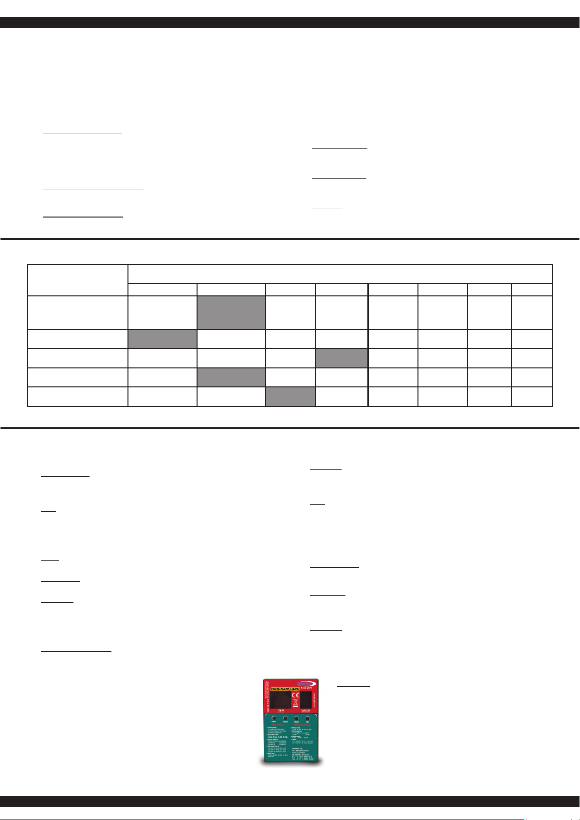
Per aggirare la programmazione tramite il pulsante Setup, il regolatore può anche
essere programmato facilmente tramite la scheda di programmazione venduto separa-
tamente (Cod. 081454).
GB
This ESC is  tted with many useful functions and to help you to be able to make the most of the
various options they are explained below. Please use the programming table shown on page 6
together with these explanations to program your ESC quickly and effectively:
1. Drive mode:
If option 1 is selected in Drive mode, the vehicle will only drive forwards and the brake is
active which make this mode the best choice for racing. In mode 2 the vehicle can be driven
forwards or in reverse and the brake is also active. This mode is useful for general use and
training.
Note:
When option 2 is selected, moving the throttle control back past the neutral point will initially
activate the brake. If the throttle control is then moved back to the neutral position briefl y the
ESC will switch over to reverse. Moving the ESC forwards will make the vehicle drive
forwards regardless of whether it was braking or moving in reverse.
2. Drag Brake force:
In this option the drag braking force can be set. The value is set as a percentage and the
values are from 0 to 40%
3. Low voltage:
In this option you can set the low voltage cut-off value. The cut-off voltage can be set between
3.4 and 2.6 Volts per cell. Once the cut-off voltage has been reached the motor will stop.
4. Start Mode:
With this option you can choose how the vehicle will accele rate when full throttle is applied
and you can set the value between ‘Soft‘ and ‘Very Aggressive‘. Please note that if you select
one of the 2 ‘Aggressive’ modes that you will need to have batteries with a very low internal
resistance otherwise the voltage will drop due to the high current draw and the motor may
stutter. Also ensure that your motor and gearing are capable of carrying the high loads.
5. Brake Max.:
The ESC is equipped with a braking system which works proportionally to the
throttle control. This means that the further the throttle control is moved rearwards
the more braking force will be applied. A higher value here will mean that the
vehicle will brake harder but more strain will be placed on the components, for
example, the gearing.
To avoid the programming procedere with the set up botton, you can all so use the
seperatly available Programmcard (Ord.No. 08 1454).
Le caselle grigie indicano l’impostazione consigliata. The  elds which are shaded in grey indicate the factory recommended settings.
Programmazione del regolatore Programming the ESC
Fase di programmazione
Program Mode
Valori del programma
Program Value
1 2 3 4 5 6 7 8
1. Modalità di guida
Drive Mode
In avanti freno on
Forwards, brake on
avanti / indietro,
freno on
forwards / reverse,
brake on
2. Freno
Drag Brake Force
0 % 5 % 10 % 15 % 20 % 25 % 30 % 40 %
3. Sottotensione
Low Voltage
aus
OFF
2,6 V/Zelle
2,6 V/cell
2,8 V/celle
2,8 V/cell
3,0 V/celle
3,0 V/cell
3,2 V/celle
3,2 V/cell
3,4 V/celle
3,4 V/cell
4. Start modo
Start Mode
sanft
soft
normal
normal
aggressivo
aggressive
molto aggressivo
very aggressive
5. Forza frenante massima
Brake Max.
25% 50% 75% 100%
8
Collegamento della scheda di programmazione
Per collegare la scheda di programmazione al regolatore di velocità, scollegare il cavo del ventilato-
re (1) dal connettore tra i cavi del motore. Collegare il cavo alla scheda di programmazione, accer-
tandosi che il cavo sia collegato correttamente (vedi schema di collegamento,  g. 2). Assicurarsi di
reinserire il cavo della ventola dopo aver completato la programmazione.
Connecting the programming card
To connect the programming card to the speed controller, disconnect the fan cable (1) from the
connector between the motor cables. Connect the cable to the programming
card, making sure that the cable is connected correctly (see connection diagram, Fig. 2). Be sure to
reinsert the fan cable after completing the programming.
Nota importante:
Oltre ai segnali lampeggianti del LED rosso, sono generati anche segnali acustici dal motore. Al
termine di ogniprogrammazione, il regolatore deve essere prima spento. Dopo il riavvio, la nuova
con gurazione avrà effetto.
Important note:
In addition to the red LED blinking, the motor will omit an acoustic signal. After every change to
the values the ESC must be switched off to store the values. The new settings will not be effective
until the ESC is re-started.
IT - Struttura del menu del regolatore GB - Menu structure
Accendere il regolatore, mentre si
preme il tasto ‚SET‘.
Press and hold the ‘SET‘ button
down and switch the receiver on
Il LED rosso lampeggia
The red LED blinks
Accendere il trasmettitore
Switch transmitter ON
Il LED verde lampeggia una volta
The green LED blinks once
Il LED verde lampeggia 2 x
The green LED blinks twice
Il LED verde lampeggia 3 x
The green LED blinks 3 times
Il LED verde lampeggia X x
The green LED blinks X times
Premere il
pulsante
per 3 secondi
Press the button
for 3 seconds
Premere il
pulsante
per 3 secondi
Press the button
for 3 seconds
Premere il
pulsante
per 3 secondi
Press the button
for 3 seconds
Lasciare il tasto
Release button
Lasciare il tasto
Release button
Lasciare il tasto
Release button
Lasciare il tasto
Release button
Premere il
tasto
Press button
Premere il
tasto
Press button
Premere il
tasto
Press button
Premere il tasto
Press button
Programmazione Fase 1,
modalità di guida
Program option 1, Drive mode
Fase di programmazione 2,
modalità di frenata
Program option 2, Brake mode
Fase di programmazione 3,
sottotensione
Program option 3, Low voltage cut-off
Phase de programmation X
Program Option
Il LED rosso lampeggia una volta, cioè, signi ca andare avanti con
freno. Red LED blinks once indicating forwards and brake.
rote LED blinkt zweimal, d.h. Vorwärts- und Rückwärtsfahrt mit Bremse
The red LED blinks twice indicating forwards, reverse and brake.
rosso|red LED lampeggia|blinks 1x, ►0 %
rosso|red LED lampeggia|blinks 2x, ►5 %
rosso|red LED lampeggia|blinks 3x, ►10 %
rosso|red LED lampeggia|blinks 4x, ►15 %
rosso|red LED lampeggia|blinks 5x, ►20 %
rosso|red LED lampeggia|blinks 6x, ►25 %
rosso|red LED lampeggia|blinks 7x, ►30 %
rosso|red LED lampeggia|blinks 8x, ►40 %
rosso|red LED lampeggia|blinks 1x, ►aus
rosso|red LED lampeggia|blinks 2x, ►2,6 V
rosso|red LED lampeggia|blinks 3x, ►2,8 V
rosso|red LED lampeggia|blinks 4x, ►3 V
rosso|red LED lampeggia|blinks 5x, ►3,2 V
rosso|red LED lampeggia|blinks 6x, ►3,4 V
Si prega di premere il tasto ‚SET‘ per ogni modi ca del valore corrente,
il LED rosso indica ciascuno dei valori, lampeggiare una volta signi ca
che è impostato su valore 1, due volte sul valore 2 ecc.
Press the ‘SET‘ button to select the desired value. The red LED will
indicate which value is selected. 1 X blink indicates value 1, 2 x blinks
indicate value 2 etc.
Tutte le fasi seguenti di programmazione si svolgano nella stessa maniera.
All of the other menu options are accessed in the same manner.
Cavo della ventola
Fan cable
Schema di collegamento
Connect memory card
9
079989
079989
505074
505071
505071
505071
505073
505071
505085
505085
505155
505085
505058
059106
177463
059096
059097
505078
505075
505075
505060
505072
079996
079996
505072
Montaggio differenziale
Differential assembly
Montaggio di trasmissione anteriore
Front gearbox assembly
10
505080
50 5080
505081
505079
505054
505054
505057
059112
505082
079996
079996
079989
079989
059109
059110
059111
Montaggio sterzo anteriore a quadrilatero
Steering hub and front suspension arm assembly
Prima dell’uso del prodotto si prega di veri care tutti i
bulloni ed i collegamenti della parte elettronica. Il veicolo
disponedi una sospensione anteriore Pivot Ball. Questo ha
numerosi vantaggi. E‚ molto robusto e di facile manutenzi-
one. L’impostazione di fabbrica non permette che gli alberi
di trasmissione saltano fuori durante la guida. Per qualsiasi
modello in azione, delle parti meccanica si possono
allentare tramite i vibrazioni. Un minimo gioco può essere
suf ciente che durante la guida si perdono gli alberini.
Pertanto, è anche necessario assicurarsi che tutti i bulloni,
dadi e vite siano controllati prima di ogni utilizzo. Con la
vita a sfera (cod. 505081 vedi lista di ricambio) si regola il
giusto  ssaggio di questa parte meccanica. Consigliamo
di avvitare la vita superiore e inferiore nel stesso modo,
in modo di non causare un bloccasterzo (tramite gli alberi
di trasmissioni) durante la manovra di sterzo. Ma di fare
anche bene attenzione di non lasciare un gioco troppo
grande, altrimenti si rischia di perdere gli alberi di trasmissi-
one. La calotta esterna in plastica a (505080) serve solo
per  ssare il fuso a snodo sulla vite a sfera. Consigliamo
di non avvitare questo coperchio in modo troppo serrato.
Before each use make sure to check all bolt connections
and cable connections. Your vehicle has a pivot front sus-
pension. This has a number of advantages. It is very ro-
bust and easy to maintain. The set-up of the car has been
done so the drive shaft will not pop out. As with any model,
screws and bolts can losen during break-in of the car. This
can result in tolerance of the drive shaft. The drive shaft
can then pop out if high pressure is applied. The inner ball
screw (item No.: 505081) will enable you to adjust the to-
lerance resulting in  ne adjustments of the track width. For
best results when setting up the pivot ball for the  rst time,
please always adjust the upper and lower pivot in the same
way. Fasten as far as the pivot can still be pulled up and
down easyly but not as far that it will pop out if you give full
steering angle. The outer plastic socket screw (item No.:
505080) is only used for securing of the steering knuckle.
This should not be too tight, otherwise the steering is not
smooth and the handling can be adversely affected.
sinistra
left
destra
right
sinistra
left
Montaggio sterzo e braccio oscillante
Steering hub and rear suspension arm assembly
destra
right
11
059104
059107
059100
059086 177443
059108
059070
059075
177143
059080
177143
059101
Montaggio ammortizzatore anteriore
Front shock assembly
Montaggio di snodo e protezione dagli impatti
Front suspension and Bumper assembly
12
059075
059083
059083
177443
059081
059074
Montaggio Ammortizzatore posteriore
Rear shock assembly
Installazione Ammortizzatore anteriore
Front shock installation
Montaggio servosaver
Steering bell crank and servo saver assembly
13
059073
505058
177463
177463
059113
130158
505026
059085
505390
505388
505475
506119
Montaggio servo
Servo assembly
Montaggio del motore e pignone
Motor mount assembly
Montaggio frizione antisaltellamento
Slipper set assembly
14
059090 059097
059082
177443
059099
177143
059080
059108
059081
177463
505078
505075
505075
505028
079996
trasmissione posteriore di montaggio
Rear gearbox assembly
Montaggio posteriore a quadrilatero
Rear Suspension assembly
15
059106
059072
059078
059077 059101
059078
177143
177143
177143
505386
070806
505054
505054
505057
assemblaggio indietro
Rear chassis area assembly
Montaggio posteriore assale
Rear hub assembly
Montaggio superiore posteriore a quadrilatero
Rear upper rod set assembly
16
177443
059099
177443
177463
059079
177143
059081
177463
177143
505386
177463
059081
059071
059083
177463
177463
Montaggio Ammortizzatore posteriore
Rear shock assembly
Montaggio barre scanalate e servo
Steering rod set and servo set assembly
L‘installazione della piastra radio
Radio tray set assembly
17
505058
081448
505285
177143
059096
059084
059109
059273
059103
059091
059103
059103
177143 505032
505032
059273
505032
505053
505060
505060
505053
Cut off the pins on the body post set and insert it into the recess on the wing mount set.
Secure the pins with the set screws. If the pins do not  t, you can  le them.
ricevitore e controllore di montaggio
Receiver box ESC set assembly
Montaggio corpo montaggio posteriore
Rear body post mount assembly
Montaggio del pneumatico e spoiler
Tire and Wing assembly
18
A
A
B
BIT - Impostazione dell’assetto / sospensione
I seguenti impostazioni sono possibile:
Convergenza anteriore
A Convergenza negativa: Sterzo e meno diretto e la
macchina tende a sovras-
terzare. Guida diritta più precisa.
B Convergenza positiva: Sterzo e più diretto e la
macchina
tende a sottosterzare.
Guida diritta
meno precisa.
GB - Suspension Settings
The following settings are possible:
toe-in / toe-out
A Toe-in: The responsiveness of the steering is
less direct and the vehicle tends to
oversteer, but it has better directional
stability.
B Toe-out: More direct steering response and
understeer, but has a worse directional
stability.
Tenditore
girare più breve = Toe-out
girare più = Convergenz
Turnbuckle
turn shorter = Toe-out
turn more = Toe-in
IT - Punti impostazione GB - Setting points
Spring tension
(less or more clip)
Suspensione molla
(basso o meno clip)
Suspensione molla
(basso o meno clip)
Shock angle
Inclinazione posteriore Inclinazione anteriore
Toe, front
Inclinazione
Caster
Spring tension
(less or more clip)
Shock angle
rear / top
Rear camber
Angolo sospensione
posteriore / sopra
Angolo sospensione
IT - Inclinazione alto/basso anteriore
Basso: Inclinazione bassa ha una guida dritta
peggiore, ma un sterzo più preciso e una
migliore entrata in curva.
Alto: Inclinazione alta ha una guida dritta miglio-
re, ma un sterzo meno preciso e l’entrata
in curva peggiore.
GB - Front caster high / low
Less caster: Less caster has a worse directional
stability, but provides a better steering on
corner entries.
High caster: A higher caster has a better directional
stability, but can result in worse corner
turn-in.
Angolo di inclina-
zione
Caster angle
Clip
montato anteriore =
Inclinazone alto
montato posteriore =
Inclinazione basso
Clip
front mounted =
higher caster
rear mounted =
lower caster
Precarico molla
(meno o più clip)
Precarico molla
(meno o più clip)
Spring tension
(less or more clip)
19
A
A
BB
teso
 r m
morbido
soft
Angolo sospensione
Shock angle
Angolo sospensione
Shock angle
Rear camber
IT - Campanatura - Positivo / Negativo anteriore e
posteriore
È possibile regolare la campanatura anteriore ruotan-
do una delle viti interne della sospensione anteriore pi-
votante. Ruotare entrambe le viti uniformemente verso
l’interno o verso l’esterno per regolare la carreggiata.
Per regolare la campanatura posteriore, ruotare l’asta
della guida posteriore.
A Negativo:
Migliore aderenza nel terreno. Poiché i bordi delle
ruote si sollevano nel sottosuolo mentre la
macchina entra in curva. Questo permette una
velocità più elevata nelle curve. Consigliamo ca.
1,5 gradi negativo anteriore e 0 grado posteriore.
Inclinazione eccessiva causa un peggioramento
della qualità guida.
B Positivo:
Inclinazione positivo è da evitare, dato che questo
causa un guida non precisa.
GB - Negative / positive camber front and rear
You can adjust the front camber by turning one of
the inner screws on the pivot front suspension. Turn
both screws equally inwards or outwards to adjust the
track width. To adjust the rear camber, turn the rear
track rod.
A Negative camber:
Better grip on terrain, as the edge of the wheels
stem into the ground allowing higher cornering
speed. We recommend approx. imately 1.5
degrees negative front and an ave rage of 0
degree to the rear. An excessive negative camber
angle can deteriorate the ride quality.
B Positive camber:
A Positive camber should be avoided in your
vehicle due to poorer ride quality.
Inclinazione
posteriore
Inclinazione
(Solo vite interna)
Front camber
(only inner screw)
IT - Angolo sospensione morbido/teso anteriore e posteriore
Morbido = Sterzo diretto
Teso = Sterzo meno diretto
GB - Damper angle soft / fi rm front and rear
To adjust the damper angle, remove the screw on the suspension arm,
adjust the angle and tighten it again.
Soft = More direct steering
Firming = Less direct steering
20
IT - Pezzi di ricambio GB - Spare parts
No. 505285
Box ricevente
Receiver Box
No. 506119
Servo
Servo
No. 05 9070
Chassis
Chassis
No. 05 9074
Servo Saver Set
Steel Turnbuckle set
No. 05 9111
Braccio trasversale in basso
posteriore
Rear lower suspension set
No. 05 9075
Ammortizzatore corto lungo
Shock set front/rear
No. 05 9101
Asse 2pz.
Wheel axle rear/front 2 pcs.
No. 05 9071
Piastra radio
Radio tray
No. 505032
Supporto batteria
Battery case
No. 05 9076
Albero motore davanti
Front drive shaft set
No. 08 1448 60 A
Regolatore Speed Ampere
Brushless
Brushless ESC
No. 05 9072
Albero motore centro
Central drive shaft set
No. 05 9077
Albero motore dietro
Rear drive shaft set
No. 05 9107
Adattatore dell ruota
Axle shaft connector
No. 05 9073
Supporto servo
Servo mount set
No. 05 9108
Supporto braccio trasversale
davanti/dietro
Suspension  xed rear/front
No. 05 9112
Braccio trasversale in basso
dietro
Rear upper Steering rod
No. 05 9103
Dado per la ruota
Wheel nut
No. 05 9110
Braccio trasversale in basso
davanti
Front lower suspension set
No. 05 9109
Braccio trasversale in alto
davanti
Front upper suspension set
No. 05 9104
Anello-O+perno per adatta-
tore ruota
O-ring and clip set
No. 05 9113
Direzzionale servo
Servo pulling rod set
No. 50 5074
Cassa diff.
Differential case set
No. 05 9092
Carrozzeria
Body
No. 05 9093
Carrozzeria chiara
Clear body coloured
No.05 9084 M3 x 5
Vis sans tête
Set screw
No. 50 5085
Perno A diff
Differential bevel gear set
No. 13 0158
E-Motor Brushless
Brushless Motor
No. 05 9114
Tirante trasversale 2pcs
Steering rod connecting set
No. 505390
Pignone motore
Motor gear set
No. 05 9097
Support amortisseur
Shock plate set
No. 50 5071
Perno B diff.
Differential bevel gear set
No. 05 9105
Ruota+Cerchio
Wheel + Tire
No. 05 9090
Supporto Spoiler
Wing mount set
No. 05 9098
Paraurti davanti
Front bumper set
No. 50 5072
Kegelzahnrad m. Welle
Main gear
No. 505388
Slipper Set
Slipper set
No. 05 9091
Spoiler posteriore
Wing
No.05 9096
Supporto carrozzeria
Body post set
No. 05 9099
Pare-chocs arrière
Rear bumper set
No. 50 5073
Perno
Bevel gear
No. 50 5075
Cassa esterna diff.
Gear box set
No. 50 5079
Steering hub set
Steering hub set
No. 50 5028
Perno braccetti
Suspension arm shaft set
No. 50 5080
Cuscinetto
Ball head nut set
No. 50 5054
Perno braccetto
Suspension arm shaft set
No. 50 5081
Vita Lenk.
Ball head screw set
No. 50 5078
Supporto diff. ant+post
Shock mount set

Other manuals for Ultra BL 8 2,4 GHz

4

This manual suits for next models

1

Other Jamara Motorized Toy Car manuals

Jamara Runty Mini Quad 6 V User manual

Jamara

Jamara Runty Mini Quad 6 V User manual

Jamara 460200 User manual

Jamara

Jamara 460200 User manual

Jamara Mercedes-Benz G 55 AMG 2,4GHz User manual

Jamara

Jamara Mercedes-Benz G 55 AMG 2,4GHz User manual

Jamara MB Arocs 2,4 GHz User manual

Jamara

Jamara MB Arocs 2,4 GHz User manual

Jamara 460447 User manual

Jamara

Jamara 460447 User manual

Jamara Ferrari 458 Italia User manual

Jamara

Jamara Ferrari 458 Italia User manual

Jamara Ice Tiger EP 2,4 GHz User manual

Jamara

Jamara Ice Tiger EP 2,4 GHz User manual

Jamara Ford M-Sport Fiesta WRC 2015 User manual

Jamara

Jamara Ford M-Sport Fiesta WRC 2015 User manual

Jamara Ride on Traktor Big Wheel 12V User manual

Jamara

Jamara Ride on Traktor Big Wheel 12V User manual

Jamara 50 7550 User manual

Jamara

Jamara 50 7550 User manual

Jamara Bugatti Chiron User manual

Jamara

Jamara Bugatti Chiron User manual

Jamara Derago XP1 User manual

Jamara

Jamara Derago XP1 User manual

Jamara Strong Bull 460825 User manual

Jamara

Jamara Strong Bull 460825 User manual

Jamara Akron BL RTR 2,4 GHz User manual

Jamara

Jamara Akron BL RTR 2,4 GHz User manual

Jamara Mercedes-AMG GT R User manual

Jamara

Jamara Mercedes-AMG GT R User manual

Jamara Mercedes-Benz Antos 2,4GHz User manual

Jamara

Jamara Mercedes-Benz Antos 2,4GHz User manual

Jamara 403128 User manual

Jamara

Jamara 403128 User manual

Jamara BMW i8 User manual

Jamara

Jamara BMW i8 User manual

Jamara Mercedes-Benz E 350 Coupe User manual

Jamara

Jamara Mercedes-Benz E 350 Coupe User manual

Jamara Veloce EP User manual

Jamara

Jamara Veloce EP User manual

Jamara Mercedes-AMG F1 W11 EQ Performance User manual

Jamara

Jamara Mercedes-AMG F1 W11 EQ Performance User manual

Jamara Hillriser Crawler 2,4 GHz User manual

Jamara

Jamara Hillriser Crawler 2,4 GHz User manual

Jamara 460274 User manual

Jamara

Jamara 460274 User manual

Jamara Porsche 911 Carrera User manual

Jamara

Jamara Porsche 911 Carrera User manual

Popular Motorized Toy Car manuals by other brands

ECX Ruckus ECX03002 instruction manual

ECX

ECX Ruckus ECX03002 instruction manual

Rollplay Volkswagen Camper Van Assembly instructions

Rollplay

Rollplay Volkswagen Camper Van Assembly instructions

FMS 1:12 TOYOTA FJ45 Pick-up instruction manual

FMS

FMS 1:12 TOYOTA FJ45 Pick-up instruction manual

VBC Racing Flash-04 instruction manual

VBC Racing

VBC Racing Flash-04 instruction manual

ECX ECX3000S Manuale d'istruzioni

ECX

ECX ECX3000S Manuale d'istruzioni

Duratrax Axis Assembly and operation manual

Duratrax

Duratrax Axis Assembly and operation manual

Matco Tools ROCK ROVER RC CAR owner's manual

Matco Tools

Matco Tools ROCK ROVER RC CAR owner's manual

Roche Rapide P10 manual

Roche

Roche Rapide P10 manual

Famosa Disney Princess S-Miles quick start guide

Famosa

Famosa Disney Princess S-Miles quick start guide

WRC GT4-2 instruction manual

WRC

WRC GT4-2 instruction manual

MIP X-Duty Instruction guide

MIP

MIP X-Duty Instruction guide

Smoby Builder Max Assembly manual

Smoby

Smoby Builder Max Assembly manual

Team Losi mini SCT Operation manual

Team Losi

Team Losi mini SCT Operation manual

Xray X12 instruction manual

Xray

Xray X12 instruction manual

Horizon Hobby AXI03006 instruction manual

Horizon Hobby

Horizon Hobby AXI03006 instruction manual

REVELL '66 Chevy SS-396 Hardtop Assembly manual

REVELL

REVELL '66 Chevy SS-396 Hardtop Assembly manual

Famosa Feber Ferrari F430 quick start guide

Famosa

Famosa Feber Ferrari F430 quick start guide

Mattel Hot Wheels DAREDEVIL DERBY instructions

Mattel

Mattel Hot Wheels DAREDEVIL DERBY instructions

manuals.online logo
manuals.online logoBrands
  • About & Mission
  • Contact us
  • Privacy Policy
  • Terms and Conditions

Copyright 2025 Manuals.Online. All Rights Reserved.