20/16
No. 006144 Air Trainer 46
ES
Highlights:
• Fuselaje de bra de vidrio reforzada en madera
• Alas hechas de madera en la construcción de costilla
• Kit de construcción de madera • Ideal para principiantes • Corte a laser
Funciones: • Timón • Ascensor • Alerón • Gas
Contenido del kit: • Modelo • Ruedas • Alambre para tren de aterrizaje • Accesorios
• Instrucciones/Planes de construcción
Accesorios recomendados:
Motor electrico A2820/6 13 2820
Hélice APC 10 x 7 34 0061
4 x Servos Nitro Q7 JR 03 3215
3 x Servos Elektro Q7 JR 03 3215
Batería 14,8 V 3700 mAh 14 1380
Emisora FCX 6 Pro Tel 2,4 GHz 06 1260
Datos técnicos:
• Medidas: Envergadura: ~ 1600 mm • Longitud: ~ 1240 mm Peso: ~ 1900 g
Salvo error y omisión.
GB
Highlights:
• Fuselage made of balsa and plywood • Wings made of wood in rib construction
• Wooden construction kit • Ideal to have with you at all times • Laser cut kit
Functions: • Aileron • Elevator • Vertical n • Throttle
Box contents: • Modell • Wheels • Undercarriage • Accessories • Instructions/Planes
Recommended accessories
Electric motor A2820/6 13 2820
Propeller APC 10 x 7 34 0061
4 x Servos Nitro Q7 JR 03 3215
3 x Servos Electric Q7 JR 03 3215
Battery 14,8 V 3700 mAh 14 1380
Transmitter FCX 6 Pro Tel 2,4 GHz 06 1260
Technical data:
• Wing span: ~ 1600 mm • Length: ~ 990 mm • Weight: ~ 1240 g
No responsibility is taken for the correctness of this information. Subject to change without prior
notice. Errors and omissions excepted
ES - Montaje del ala derecha
Atención!!
El ala es la parte más importante de su avión, trabaje con mucho cuidado con el pegado,
tómese su tiempo para hacer todo correctamente!
GB - The following steps are showing right wing.
Caution!!
Main wing is one of the most important parts of air plane. Adhering slip-off between the right
and the left wings may give a great infl uence upon the fl ying performance and your airplane
may come apart while fl ying due to incomplete adhering. Accurately build the wings and
completely adhere them.
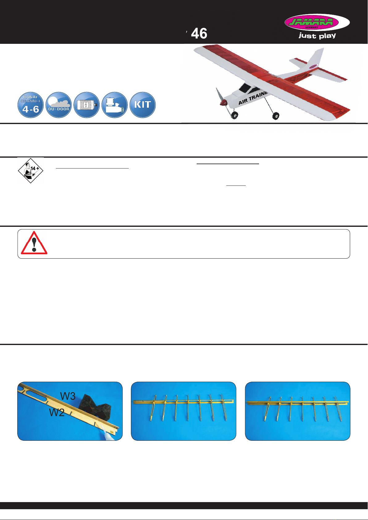
Montaje del ala derecha
Coloque las piezas W3 y W2 sobre la super cie de trabajo. Co-
loque la barra W3 en la parte inferior de W2. Use un ángulo para
unir rmemente la barra.
Nota: Asegúrese de que las dos partes (W2 y W3) estén en un
ángulo de 90° entre sí.
The following steps are showing right wing.
Place the W3 hard wood strip and W2 on the working table. Use
instant glue to secure the W3 on the bottom of W2; make sure
the alignment of both bottom lines.
Hint: you can use triangle ruler when secure W3 on W2.
Fije las costillas W8 - W9 (véase el plan para la secuencia) en el
larguero (larguero principal W2/W3). Después de jar las costil-
las a los largueros, alinéelos con un ángulo de 90° con respecto
al larguero principal y péguelos con el pegamento.
Refer to the assemble drawing inside the box and t ribs W8
– W9 onto the W2 combination. Use triangle ruler between the
ribs and W3; make sure the angle is 90 degree and drop some
instant glue to secure ribs in place.
Pegue la tira W2 en la parte superior del larguero principal.
Try to t W2 on the top of the middle beam and use instant glue
to secure it in place.
ES - Instrucciones
GB - Instruction
ES - Información general
Jamara K. no se hace responsable de los daños causados al producto en sí o por medio de esto,
a menos que esto se debe al mal funcionamiento o errores de manejo. El cliente solo tiene la re-
sponsabilidad completa para el uso y manejo adecuado, incluyendo, sin limitaciones, el montaje,
el proceso de carga, el uso de hasta la elección de la zona de aplicación. Por favor, consulte las
instrucciones de uso y funcionamiento, contiene información y avisos importantes.
GB - General information
Jamara e.K. is not liable for any damage caused to the product itself or by it, if this is due to impro-
per operation or handling errors. The customer alone bears the full responsibility for the proper use
and handling, including in particular, assembling, charging and using the model, and selecting the
area in which to use it. Please refer to the operating and user instructions, which contain important
information and warnings.
ES - Por favor, lea atentamente el manual de instrucciones completo antes de poner en funcionamiento el modelo.
GB - Read the complete instructions carefully before using the model.
ES - Artículo de modelismo - No es un juguete
Apto para mayores de 14 años.
Atención: No apto para niños menores de 36 meses.
PELIGRO DE ASFIXIA.
Contiene partes pequeñas que se pueden tragar.
Mantenga este fuera del alcance de los niños pequeños.
Este dispositivo no está diseñado para ser utilizado por personas
(incluyendo niños) con capacidades físicas, sensoriales o mentales
limitadas o por falta de experiencia y/o conocimiento.
• Cuando monte y utilice el modelo, manténgalo alejado de niños para
los que el modelo no sea adecuado.
• Montar el modelo exactamente según las instrucciones y el plano.
GB - For model building only - Not a toy!
Not suitable for people under 14 year.
Warning: Not suitable for children under 36 months.
RISK OF SUFFOCATION!
Contains small parts which can be swallowed.
Keep away necessarily from children.
This product is not intended for use by individuals (including children)
with reduced physical, sensory or mental capabilities or lack of experience
and / or knowledge.
• Keep the model away from Children in case it is not appropriate to be
used by a Child (see note of age). Keep children away during assembly.
• Build the model exactly as directed and plan together.


