manuals.online logo
Brands
  1. Home
  2. •
  3. Brands
  4. •
  5. Jamara
  6. •
  7. Transmitter
  8. •
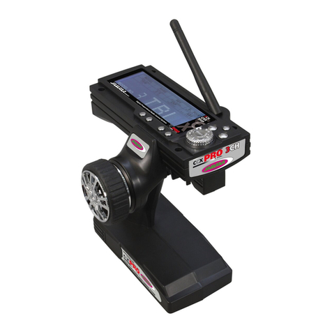
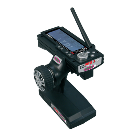
  9. Jamara CCX Lipo 2,4 GHz 3 CH User manual

Jamara CCX Lipo 2,4 GHz 3 CH User manual

DE - Gebrauchsanleitung
GB - Instruction
CCX Lipo 2,4 GHz 3 CH
Fernsteuerung | Transmitter
No. 061201
15/1644/20
DE - Allgemeine Hinweise
JAMARA e.K. übernimmt keine Haftung für Schäden, die an dem Produkt selbst oder durch dieses
entstehen, sofern diese auf falsche Bedienung oder Handhabungsfehler zurückzuführen sind. Der
Kunde allein trägt die volle Verantwortung für die richtige Bedienung und Handhabung; dies umfasst
insbesondere die Montage, den Ladevorgang, die Verwendung bis hin zur Wahl des Einsatzberei-
ches. Bitte beachten Sie hierzu die Bedienungs- und Gebrauchsanleitung, diese enthält wichtige
Informationen und Warnhinweise.
GB - General information
JAMARA e.K. is not liable for any damage caused to the product itself or by it, if this is due to impro-
per operation or handling errors. The customer alone bears the full responsibility for the proper use
and handling, including in particular, assembling, charging and using the model, and selecting the
area in which to use it. Please refer to the operating and user instructions, which contain important
information and warnings.
Konformitätserklärung
Hiermit erklärt JAMARA e.K., dass das Produkt‚ “CCX Lipo 2,4 GHz, No. 061201“
den Richtlinien 2014/53/EU, 2011/65/EU entspricht.
Der vollständige Text der EU-Konformitätserklärung ist unter der folgenden
Internetadresse verfügbar: www.jamara-shop.com/Konformitaet
GB - Certicate of Conformity
Hereby JAMARA e.K. declares that the product “CCX Lipo 2,4 GHz, No. 061201“ complies with
Directive 2014/53/EU, 2011/65/EU.
The full text of the EU Declaration of Conformity is available at the following Internet address:www.
jamara-shop.com/Conformity
Lieferumfang
• Fernsteuerung
• Empfänger
• Akku LiPo 3,7 V 800 mAh 2,96Wh
• USB Ladekabel
• Anleitung
Empfohlenes Zubehör
8 x AA Batterie Art.-Nr. 140267 (VE 4 Stück)
Ausstattung
• 3 Kanäle
• 2,4 GHz System
• Dual Rate
• Servo Revers (Gas/Lenkung)
• Justierung Servomitte
• Modulationsart AFHDS
• Modelltypen Auto, Schi󰀨
• Betriebsspannung 3,7 V
• Unterspannungswarnung
• USB-Ladebuchse
• Fail-Safe am Empfänger
• Gewicht 270 g
• Maße 156 x 223 x 94 mm
Empfänger CCX Pro 2,4 GHz
Art.-Nr. 06 1185
Technische Daten:
Frequenzband 2,4 GHz
Modulationsart AFHDS
Betriebsspannung 4,8 - 7,4 V DC
Servoauösung 10 Bit (1024 Schritte)
Abmessungen 33 x 22 x 12 mm
Gewicht 5 g
Box contents:
• Transmitter
• Receiver
• Battery LiPo 3,7 V 800 mAh 2,96Wh
• USB charging cable
• Instruction
Recommended Accessories
8 x AA Batteries Ord. No. 140267 (4 pieces)
Features:
• 3 channel
• 2,4 GHz System
• Dual Rate
• Servo reverse (Gas/steering)
• Adjustment of servo centre
• Modulation AFHDS
• Model types Car, boat
• Operating range 3,7 V
• Low-Voltage warning
• Charging socket USB
• Fail Safe on receiver
• Weight 270 g
• Size 156 x 223 x 94 mm
Receiver CCX Pro 2,4 GHz
Ord.No. 06 1185
Technical data:
Frequency 2,4 GHz
Modulation AFHDS
Operating voltage 4,8 - 7,4 V DC
Servo resolution 10 Bit (1024 steps)
Dimensions 33 x 22 x 12 mm
Weight 5 g
Modellbauartikel - Kein Spielzeug!
Bitte lesen Sie die komplette Bedienungsanleitung und Sicherheitshinweise sorgfältig
durch bevor Sie das Modell in Betrieb nehmen.
Achtung! Warnhinweise / Sicherheitshinweise unbedingt komplett lesen.
Diese dienen Ihrer Sicherheit und können Unfälle / Verletzungen vermeiden.
For model building only - Not a toy!
Read the complete instructions and security instructions carefully before using the
model.
Caution! Please fully and carefully read warnings/ safety instructions.
These are for our own security and can avoid accidents/injuries.
Beachten Sie unbedingt folgende Hinweise:
• Bevor Sie den Empfänger einschalten stellen Sie sicher, dass der Gasgeber auf Motor-Aus steht.
• Stellen Sie sicher, dass der Sender und der Empfänger richtig zusammen arbeiten, richtig
gebunden sind.
• Schalten Sie immer zuerst den Sender und dann den Empfänger ein.
• Schalten Sie immer zuerst den Empfänger, dann den Sender aus.
• Führen Sie vor dem Start einen Reichweiten- und einen Funktionstest durch.
• Gefährden Sie weder Menschen noch Tiere.
• Setzen Sie die Anlage bzw. das zu steuernde Modell nur in geeignetem Gelände ein.
• Bei Sturm, Regen oder einem Gewitter dürfen Sie Ihre Anlage nicht einsetzen.
• Wenn die Anlage länger nicht eingesetzt wird, entfernen Sie die Batterien aus dem Sender.
Following should be strictly adhered to:
• Before Switching on the system ensure that throttle stick is in the o󰀨 position.
• Check that the transmitter and receiver are compatible and bonded to one another.
• Always switch the transmitter on  rst and then the receiver.
• Always switch the receiver o󰀨  rst and then the transmitter .
• Complete a full range and function test before every take-o󰀨 .
• Never over- y people and do not allow your model to endanger people or animals.
• Do not  y near to over-head cables, buildings or air elds.
• The system must not be operated in rain, or thunder storms.
• If you do not intend to use the transmitter for a long period, remove the batteries.
Frequency bands: 2.4 GHz Frequency range: 2405,5 – 2475,0 MHz EIRP: < 40 mW (max. power transmitted)

2
DE - Akkus laden
Achten Sie vor einem Einsatz darauf, dass die Zellen voll aufgeladen sind. Wegen der Selbstentla-
dung müssen Sie vor jedem Einsatz die Akkus nachladen. Beachten Sie unbedingt die Hinweise des
Herstellers der von Ihnen verwendeten Zellen.
Setzen Sie unbedingt ein passendes Ladekabel ein, lassen Sie sich von Ihrem Fachhändler be-
raten. Nachdem die Zellen voll aufgeladen sind, trennen Sie die Verbindung zum Sender bzw. zur
Ladebuchse der Empfangsanlage.
Entnehmen Sie den Akku dem Sender und dem Modell, wenn Sie es für längere Zeit nicht einset-
zen. Beim Senderakku laden gehen Sie wie folgt vor:
1. Legen Sie die Akkuzelle polrichtig ein.
2. Stecken Sie das Ladekabel an einen geeigneten USB-Anschluss.
3. Stecken Sie das Ladekabel in die Ladebuchse des Senders.
4. Ziehen Sie das Ladekabel ab, sobald die Zellen voll aufgeladen sind.
GB - Charging the battery
Ensure that the cells are fully charged before using the system. Please be aware that due to the
self-discharge characteristics of this type of cells that they should always be fully charged prior to
use. Please refer to the battery manufacturers recommendations regarding charging current etc.
Use only a high quality charging cable which is suitable for this type of cells. For further information
please contact your local dealer. Once charging is complete, always disconnect the batteries from
the charger.
Remove the batterie from the model and transmitter if you do not intend to operate it for a longer
period of time. To charge teh transmitter batteries please proceed as follows:
1. Fit the batterie observing the correct polarity.
2. Connect the charging cable with a suitable USB port.
3. Connect the charging cable to the transmitter.
4. Unplug the charger as soon as the batteries are full.
DE
Durch eine sinnvolle Anordnung von Tastern, Schaltern und LED-Anzeigen, kann der Sender CCX
Lipo 2,4GHz 3CH Anlage schnell und problemlos programmiert werden. Beide Kanäle können ge-
trimmt werden, außerdem lässt sich die Laufrichtung umkehren. Weiterhin steht eine Dual-Rate
Funktion zur Verfügung. Eine LED signalisiert den Ladezustand der Senderstromversorgung.
GB
Thanks to the logical and well thought out lay-out of the Programming Panel and the positioning
of the switches and LEDs the CCX Lipo 2,4GHz 3CH transmitter can be quickly and simply pro-
grammed. Both channels can be trimmed and the direction changed. Furthermore the transmitter is
equipped with a Dual Rate system and a red LED indicates the state of the battery charge.
DE - Bedienelemente
Seitenansicht
1. Programmierbox
2. 2,4 GHz Antenne
3. Lenkrad
4. Gashebel
5. Akku-/Batteriefach
6. 3-Kanal
Programmierfeld
7. Lenkungs-Trimmung
8. Lenkung Reverse
9. Power LED
10. Ein-/Ausschalter
11. Gas Reverse
12. Binde Taste
13. Gas Trimmung
14. Power Check
15. Dual Rate
DE - Rückseite
G. Ladebuchse
GB - Rear Side
G. Charge Socket
DE - Controls
Side View
1. Programming Box
2. 2,4 GHz Antenna
3. Steering Wheel
4. Throttle Lever
5. Battery Hatch
6. 3-Channel
Programming Panel
7. Steering Trim
8. Steering Reverse
9. Power LED
10. ON/OFF Switch
11. Throttle Reverse
12. Binding Button
13. Throttle Trim
14. Power Check
15. Dual Rate
1
7
8
9
10
11
12
13
14
15
2
3
4
5
6
G
33
DE - Einbau der Empfangsanlage
Achtung!
Achten Sie bei dem Anschließen der Kabel auf die richtige Polarität
(+ & - Pol), da der Empfänger ansonsten kurzgeschlossen wird.
GB - Connecting to the receiver
Warning!
To avoid any short-circuit in your receiver, please make sure to connect
the cables with correct polarity in mind.
DE - Antenne
Befestigen Sie die 2,4 GHz Antenne senkrecht, wie auf dem nebenstehenden Bild zu erkennen.
Sie dürfen die Antenne allerdings nicht an metallischen Gegenständen befestigen, die Reichweite
würde zurückgehen.
GB - Antenna
Mount the 2.4 GHz antenna vertically as shown in the diagram. Do not allow any metal object to
come into contact with the antenna or to shield it as this will reduce the range.
Modell mit Elektroantrieb
Wiring diagram for electric models
Schalter
Switch
Schalter
Switch Empfängerakku
Receiver Battery
Gasservo
Throttle Servo
Lenkungsservo
Steering Servo
Motorregler
ESC
Lenkservo
Steering
Kanal 2
2CH
Empfänger
Receiver
Empfänger
Receiver
Antriebsakku
Battery Pack
Motor
Modell mit Verbrennungsmotor
Wiring diagram for I/C engine models
Empfänger
Receiver
2,4 GHz Antenne
2,4 GHz Antenna
Fail Safe LED
CH2
Batterie / Battery
CH1
CH3/Bind
4
DE - Sender und Empfänger binden
Bei einer modernen 2,4 GHz Anlage ist es unbedingt notwendig, dass der Sender und der Empfäger
im Modell aneinander gebunden werden. Der Empfänger akzeptiert dann nur noch die Signale sei-
nes Senders. Sollten Sie aus irgendwelchen Gründen die Bindung neu durch führen wollen, gehen
Sie bitte wie folgt vor:
A. Setzen Sie den aufgeladenen Akku in den Sender ein. Lassen Sie den Sender ausgeschaltet.
B. Stecken Sie den beigefügten Bindungsstecker in den 3. Kanalausgang.
C. Schalten Sie die Empfangsanlage ein, indem Sie den Empfängerakku mit dem Empfänger ver-
binden. Die LED am Empfänger fängt an zu blinken und zeigt damit an, dass der Empfänger sich
im Bindemodus bendet.
D. Halten Sie die Bindetaste am Sender gedrückt und schalten Sie gleichzeitig den Sender ein.
E. Der Sender beginnt zu blinken und zeigt an das er im Bindemodus ist.
F. Lassen Sie die Bindetaste am Sender los und trennen Sie den Empfänger vom Empfängerakku,
bzw. schalten den Regler aus. Entfernen Sie nun den Bindungsstecker am Empfänger.
G. Schalten Sie nun den Sender aus. Die Anlage ist beim nächsten Einschalten gebunden..
H. Installieren Sie alles ordnungsgemäß und überprüfen Sie alles sehr genau
I. Sollte die Funktion nicht erfolgreich verlaufen, wiederholen Sie die Bindeprozedur.
Die folgende Abbildung stellt grasch den Bindevorgang dar und
kennzeichnet die einzelnen Elemente die bedient werden müssen.
GB - Binding the receiber to the transmitte
As with all modern 2.4GHz R/C systems the receiver must be bound to the transmitter to ensure that
the receiver will only react to signals from that transmitter. If you wish to re-bind the receiver with the
transmitter please proceed as follows:
A. Ensure that the transmitter is tted with fully charged batterie and leave the transmitter o󰀨.
B. Plug the binding plug (included) into the channel 3 socket on the receiver.
C. Switch the receiver system on by connecting the battery or turn in a BEC operating on a controller
to control. The receiver LED will begin to ash indicating that the receiver is in bonding mode.
D. Press and hold down the binding button on the transmitter whilst switching it on.
E. The transmitter will begin to  ash indicating that the receiver is in bonding mode.
F. Release the binding button on the transmitter and disconnect the receiver from the battery or turn
o󰀨 the controller. Release the binding plug from the receiver.
G. Switch of the transmitter. and remove the binding wire. The system be bound at the next start ..
H. Install all properly and check anything very precisely.
I. If the receiver fails to bond or does not function after bonding repeat the above procedure until a
successful bonding is achieved.
The following diagrams illustrate the bonding process and show
the locations of the relevant components.
DE - Fail Safe
Programmierung der integrierten FailSafe-Einheit
1. Funktionsbeschreibung
Die integrierte FailSafe-Einheit ist hauptsächlich für den Einsatz bei Booten und Fahrzeugen ge-
dacht. Sie dient dazu den Verlust des Models hervorgerufen durch einen hängenden Gaskanal bei
Signalverlust zu verhindern. Wenn der Empfänger das Signal zum Sender verliert, kehrt der Servo
oder Speedregler des Gaskanals automatisch in die zuvor eingestellte Position zurück.
2. Einstellung
a. Schalten Sie den Sender ein
b. schalten Sie den Empfänger ein. Die Signal-LED leuchtet dauernd und zeigt an, dass der Emp
fänger betriebsbereit ist.
c. Bringen Sie den Gashebel am Sender in die Brems bzw. Auslaufstellung Ihres Servos oder
Speedreglers. Halten Sie den Gashebel auf dieser Position fest.
d. Drücken Sie die Setup Taste am Empfänger. Die Signal LED blinkt für 3 Sekunden
(siehe Abb. links).
e. Die Einstellung ist gespeichert und Sie können den Gashebel wieder in die Neutralposition
bringen.
3. Testen der Einstellungen
a. Schalten Sie den Sender ein.
b. Schalten Sie den Empfänger ein.
c. Schalten Sie den Sender aus.
d. Der Empfänger verliert nun das Signal und fährt den Servo bzw. den Speedregler am Gaskanal
auf die zuvor einprogram- mierte Position zurück.
e. Folgt der Ablauf den obigen Schritten funktioniert die FailSafe-Funktion korrekt.
GB - Fail Safe
Programming of the integrated FailSafe unit.
1. Function Description
The function of protection of losing control is mainly for r/c boats and cars and keeps them away from
damage through throttle channel. When the receiver is out of control signal, the receiver of throttle
will automatically return to the initial position which set up before starting to avoid the error action.
2. Setting
a. Turn on the transmitter
b. Turn on the receiver. The signal LED will light continuously and indicates that the receiver is
ready.
c. Move the throttle lever on the transmitter in the braking or outlet position. Hold the throttle lever
in this position.
d. Press the Setup button on the receiver. The signal LED ashes for 3 seconds (see left).
e. The setting is saved and you can bring back the throttle into neutral position.
3. Testing the settings
a. Turn on the transmitter.
b. Turn on the receiver.
c. Turn o󰀨 the transmitter.
d. The receiver will now lose the signal and drives the servo or the speed control on the gas channel
to the previously programmed position.
e. If these steps work, you have set the FailSafe.
Bindetaste
Binding button
Bindungsstecker
Binding Plug
LED
Fail Save
5
DE - Einschaltreihenfolge
1. Stecken Sie alle Komponenten zu-
sammen.
2. Schalten Sie den Sender ein.
3. Verbinden Sie den Empfängerakku
mit dem Empfänger.
4. Überprüfen Sie ob die LED’s am
Sender und am Empfänger dauer-
haft leuchten
5. Das System ist eingeschaltet und
kann eingesetzt werden.
DE - Ausschaltreihenfolge
1. Empfängerakku abstecken
2. Sender ausschalten
DE - Steuerung des Modells
Mit dieser Funktion wird die Lenkung, die Richtungssteuerung durchgeführt. Bei einer Drehung
des Steuerrades, müssen die Räder der Vorderachse in die entsprechende Richtung ausschlagen.
Wenn das Rad nach rechts gedreht wird, müssen, wie im oberen Bild zu erkennen, die Räder nach
rechts ausschlagen. Im nebenstehendem Bild ist der Ausschlag für eine Linkskurve zu sehen.
Mit dem entsprechenden Umschalter (6) im Programmierfeld lässt sich, wenn notwendig, die Lauf-
richtung umpolen. Für ein feinfühligeres Steuern kann mit dem Dual-Rate Taster eine Dual-Rate
Funktion vorgegeben werden. Eine Drehung am Lenkrad in der Nähe der Neutralposition führt nur
zu relativ geringen Servoausschlägen. Der gesamte Servoweg steht aber z.B. für Wendemanöver
komplett zur Verfügung.
GB - Operating the model
This function is used to steer the model and turning the steering wheel will make the models wheels
to turn in the relevant direction. Turning the wheel to the right will make the models wheels turn to
right when viewed from above as illustrated. Moving the wheel to the left will cause the wheels to
turn to the left.
By operating the relevant switch (6) on the programming panel the direction in which the steering
moves can be reversed if required. In addition, the transmitter is equipped with a Dual Rate function.
When this function is activated the wheels of the model will move less relative to the movement of
the transmitters steering wheel around the middle position. This will allow the model to be steered
with more precision however if this function is used the total throw will still be available
for tight cornering when the steering wheel is moved to the end of it’s range.
GB - Switch on
1. Plug in all of the components.
2. Switch the transmitter on.
3. Connect the receiver battery to the
receiver.
4. Check that the LEDs on both the
transmitter and the receiver illuminate
solidly.
5. The system is now correctly switch
on and operating and can now safely
be used.
GB - Switching o󰀨
1. Disconnect the receiver battery
2. Switch o󰀨 the transmitter
Einschalten
Switching On
1. Sender
einschalten
1. Switch the
transmitter on
2. Empfänger
einschalten
2. Switch the
receiver on
1. Empfänger
ausschalten
1. Switch o󰀨
the receiver
2. Sender ausschalten
2. Switch o󰀨 the
transmitter
Ausschalten
Switching O󰀨
Lenkung
Steering
6
Gassteuerung
Trottle Lever
DE - Gassteuerung
Mit dieser Funktion werden die Vor- und Rückwärtssteuerung sowie die Geschwindigkeit gesteuert.
Wenn der Steuergeber nach hinten gezogen wird, bewegt sich das Fahrzeug nach vorn, wie auf
dem nebenstehenden Bild dargestellt.
Wenn der Steuergeber nach vorn gedrückt wird, wie auf dem unteren Bild dargestellt, bremst das
Fahrzeug zuerst ab und fährt dann rückwärts. Voraussetzung für diese Steuerung ist allerdings ein
elektrisch angetriebenes Fahrzeug, mit einem entsprechenden Speed-Controller.
GB - Trottle Lever
This function is used to control the models speed both forwards and in reverse as shown in the
illustration to the left. If the lever is pulled back towards the transmitter grip the model will accelerate
forwards.
If the lever is pushed away from the transmitter grip the model will rst brake and then accelerate
in reverse. This is providing that the model is tted with a Speed Controller which supports these
functions.
DE - Schalter für dritten Kanal:
Stellt ein Servo am dritten Kanal in Maximalausschlag nach links/rechts.
GB - Auxiliary Channel 3 Switch:
Controls auxiliary channel 3 high and low servo travel.
CH 3
7
DE - Servicehändler GB - Service centre
Reitter Modellbau Versand
Patricia Reitter
Degerfeldstrasse 11
72461 Albstadt
Tel 07432 9802700
Fax 07432 2009594
Mail [email protected]
Web www.modellbauversand.de
Modellbau-Zentral
Peter Hofer
Bresteneggstrasse 2
CH -6460 Altdorf,
Tel. +41 794296225
Fax +41 418700213
[email protected]
www.modellbau-zentral.ch
PenTec s.r.o.
distributor Jamara for Czech Republic and Slovakia
Veleslavínská 30/19
CZ -162 00 Praha 6
Tel +420 235 364 664
Mobil. +420 739 075 380
Mail servis@topdrony.cz
Web www.topdrony.cz
Bay-Tec
Martin Schaaf
Am Bahndamm 6
86650 Wemding
Tel 07151 5002192
Fax 07151 5002193
Mail [email protected]
Web www.bay-tec.de
DE DE
JAMARA e.K.
Manuel Natterer
Am Lauerbühl 5
DE-88317 Aichstetten
Tel +49 (0) 75 65/94 12-0
Fax +49 (0) 75 65/94 12-23
Mail [email protected]
Web www.jamara.com EU
CH CZ
JAMARA e.K.
Inh. Manuel Natterer
Am Lauerbühl 5 - DE-88317 Aichstetten
Tel. +49 (0) 75 65/94 12-0 - Fax +49 (0) 75 65/94 12-23
[email protected] ●www.jamara.com
Service - Tel. +49 (0) 75 65/94 12-777
kundenservice@ jamara.com
Irrtum und technische Änderungen vorbehalten. Copyright JAMARA e.K. 2020
Kopie und Nachdruck, auch auszugsweise, nur mit Genehmigung von JAMARA e.K.
All rights reserved. Copyright JAMARA e.K. 2020
Copying or reproduction in whole or part, only with the expressed permission of JAMARA e.K.
Fordern Sie noch Heute den aktuellen Hauptkatalog mit
unserem gesamten Warensortiment an.
Name _______________________________
Vorname _______________________________
Straße _______________________________
Wohnort _______________________________
Telefon _______________________________
E-mail _______________________________
Bitte senden Sie den Katalog für mich an folgenden
Fachhändler:
Ihr Fachhändler
_______________________________________________
_______________________________________________
_______________________________________________
_______________________________________________
Der Katalog wird mit der nächsten Bestellung des Händ-
lers auf Ihren Namen mitgeliefert.
Order the current catalogue with our complete
assortment of modelling goods today.
Name _______________________________
First name _______________________________
Street _______________________________
City _______________________________
Phone _______________________________
E-mail _______________________________
Please send the catalogue to the following specialist
dealer:
Your dealer
_______________________________________________
_______________________________________________
_______________________________________________
_______________________________________________
We will include a catalogue for your attention with the
next order placed by your dealer.
Gutschein Coupon

Other manuals for CCX Lipo 2,4 GHz 3 CH

2

This manual suits for next models

1

Other Jamara Transmitter manuals

Jamara FCX6 Pro Tel User manual

Jamara

Jamara FCX6 Pro Tel User manual

Jamara CCX Pro User manual

Jamara

Jamara CCX Pro User manual

Jamara CCX Pro 2,4 GHz User manual

Jamara

Jamara CCX Pro 2,4 GHz User manual

Jamara FCX6 Pro Tel User manual

Jamara

Jamara FCX6 Pro Tel User manual

Jamara CCX Pro 2,4 GHz User manual

Jamara

Jamara CCX Pro 2,4 GHz User manual

Jamara CX 2,4 GHz User manual

Jamara

Jamara CX 2,4 GHz User manual

Jamara CCX Pro User manual

Jamara

Jamara CCX Pro User manual

Jamara SCX 2,4 GHz User manual

Jamara

Jamara SCX 2,4 GHz User manual

Jamara CCX Lipo User manual

Jamara

Jamara CCX Lipo User manual

Jamara CCX Lipo User manual

Jamara

Jamara CCX Lipo User manual

Jamara FCX6 Pro Tel User manual

Jamara

Jamara FCX6 Pro Tel User manual

Jamara SCX User manual

Jamara

Jamara SCX User manual

Jamara Compa X3 Evo User manual

Jamara

Jamara Compa X3 Evo User manual

Jamara CCX Pro User manual

Jamara

Jamara CCX Pro User manual

Jamara CCX Lipo 2,4 GHz 3 CH User manual

Jamara

Jamara CCX Lipo 2,4 GHz 3 CH User manual

Jamara Compa X3 Evo User manual

Jamara

Jamara Compa X3 Evo User manual

Jamara FCX6 Pro Tel User manual

Jamara

Jamara FCX6 Pro Tel User manual

Jamara FCX6 Pro Tel User manual

Jamara

Jamara FCX6 Pro Tel User manual

Jamara CCX Pro User manual

Jamara

Jamara CCX Pro User manual

Jamara CCX Pro 2,4 GHz User manual

Jamara

Jamara CCX Pro 2,4 GHz User manual

Jamara CCX Lipo 2,4 GHz 3 CH User manual

Jamara

Jamara CCX Lipo 2,4 GHz 3 CH User manual

Jamara SCX User manual

Jamara

Jamara SCX User manual

Jamara Compa User manual

Jamara

Jamara Compa User manual

Jamara FCX6 Pro Tel User manual

Jamara

Jamara FCX6 Pro Tel User manual

Popular Transmitter manuals by other brands

Nice FLO Series user manual

Nice

Nice FLO Series user manual

Scaime eNod3-C User instructions

Scaime

Scaime eNod3-C User instructions

Enersound T?500 user manual

Enersound

Enersound T?500 user manual

Array electronic AGT600 user manual

Array electronic

Array electronic AGT600 user manual

Berker 2411 12 00 user manual

Berker

Berker 2411 12 00 user manual

Acromag DT336-0700 user manual

Acromag

Acromag DT336-0700 user manual

Endress+Hauser iTEMP TMT162 Brief operating instructions

Endress+Hauser

Endress+Hauser iTEMP TMT162 Brief operating instructions

Paso SDM200 Instructions for use

Paso

Paso SDM200 Instructions for use

Savio TR-01 User manual & warranty

Savio

Savio TR-01 User manual & warranty

CSS AssistX IR one quick guide

CSS

CSS AssistX IR one quick guide

Daniels VT-3H035-SWA3 instruction manual

Daniels

Daniels VT-3H035-SWA3 instruction manual

ipf electronic PSQ80076 manual

ipf electronic

ipf electronic PSQ80076 manual

PSM 500 Series user manual

PSM

PSM 500 Series user manual

M-system W5FV instruction manual

M-system

M-system W5FV instruction manual

Carrier B6 Series specification

Carrier

Carrier B6 Series specification

CAROL DWR-882 user manual

CAROL

CAROL DWR-882 user manual

Honeywell SMV800 user guide

Honeywell

Honeywell SMV800 user guide

Meriam Instrument 1500 SMART operating instructions

Meriam Instrument

Meriam Instrument 1500 SMART operating instructions

manuals.online logo
manuals.online logoBrands
  • About & Mission
  • Contact us
  • Privacy Policy
  • Terms and Conditions

Copyright 2025 Manuals.Online. All Rights Reserved.